Bosch PPR 250: English
English: Bosch PPR 250
OBJ_BUCH-1513-003.book Page 15 Monday, January 16, 2012 11:29 AM
English | 15
Entsorgung
f Supervise children. This will ensure that children do not
play with the electric paint roller.
Elektrowerkzeuge, Zubehör und Verpackungen sollen einer
umweltgerechten Wiederverwertung zugeführt werden.
f Children or persons that, owing to their physical, sen-
sory or mental limitations or to their lack of experience
Werfen Sie Elektrowerkzeuge nicht in den Hausmüll!
or knowledge, are not capable of securely operating
Nur für EU-Länder:
the electric paint roller, may only use this electric paint
Gemäß der Europäischen Richtlinie
roller under supervision or after having been instruct-
2002/96/EG über Elektro- und Elektronik-
ed by a responsible person. Otherwise, there is danger of
Altgeräte und ihrer Umsetzung in nationales
operating errors and injuries.
Recht müssen nicht mehr gebrauchsfähige
f Before each use, check the base unit, cable and plug. If
Elektrowerkzeuge getrennt gesammelt und
damage is detected, do not use the base unit. Never
einer umweltgerechten Wiederverwertung
open the base unit yourself, and have repairs carried
zugeführt werden.
out only by a qualified repair person using only identi-
Änderungen vorbehalten.
cal replacement parts. A damaged base unit as well as
damaged cables and plugs increase the risk of an electric
shock.
f Use only paints/coatings as specified under Intended
English
Use. Paints/coatings that are not approved (e. g., varnish,
oil-based paint, etc.) can damage the electric paint roller.
Safety Notes
f Observe possible hazards of the paint/coating. Ob-
serve the manufacturer’s working instructions for the
Read all safety warnings and all instructions.
paints/coatings. The manufacturer’s instructions must be
Failure to follow the warnings and instructions
followed in order to reduce the risk of injury.
may result in electric shock, fire and/or serious in-
jury.
f Always conduct the feed hose away from yourself and
particularly do not work from ladders or scaffolds. Trip-
Save all safety warnings and instructions for future refer-
ping over the feed hose can lead to injuries.
ence.
f Use only water-based materials for cleaning. Volatile
f Keep work area clean and well lit. Cluttered and dark ar-
solvents create an explosive environment and can damage
eas invite accidents.
the electric paint roller.
f Do not operate the power tool in explosive atmos-
Products sold in GB only: Your product is fitted with an
pheres, such as in the presence of flammable liquids,
BS 1363/A approved electric plug with internal fuse (ASTA
gases or dusts. Power tools create sparks which can ignite
approved to BS 1362).
the dust or fumes.
If the plug is not suitable for your socket outlets, it should be
f The plugs of power tools must match the outlet. Never
cut off and an appropriate plug fitted in its place by an author-
modify the plug in any way. Do not use any adapter
ised customer service agent. The replacement plug should
plugs with earthed (grounded) power tools. Unmodified
have the same fuse rating as the original plug.
plugs and matching outlets will reduce the risk of electric
The severed plug must be disposed of to avoid a possible
shock.
shock hazard and should never be inserted into a mains sock-
f Protect the machine from rain and moisture. The pene-
et elsewhere.
tration of water in a power tool increases the risk of electric
Products sold in AUS and NZ only: Use a residual current de-
shock.
vice (RCD) with a rated residual current of 30 mA or less.
f Do not misuse the cord. Never use the cord for carry-
ing, pulling or unplugging the power tool. Keep cord
Symbols
away from heat, oil, sharp edges and moving parts.
Damaged or entangled cords increase the risk of electric
The following symbols can be important for the operation of
shock.
your power tool. Please memorise the symbols and their
meanings. The correct interpretation of the symbols helps
f When operating a power tool outdoors, use an exten-
you operate the power tool better and more secure.
sion cord suitable for outdoor use. Use of a cord suitable
for outdoor use reduces the risk of electric shock.
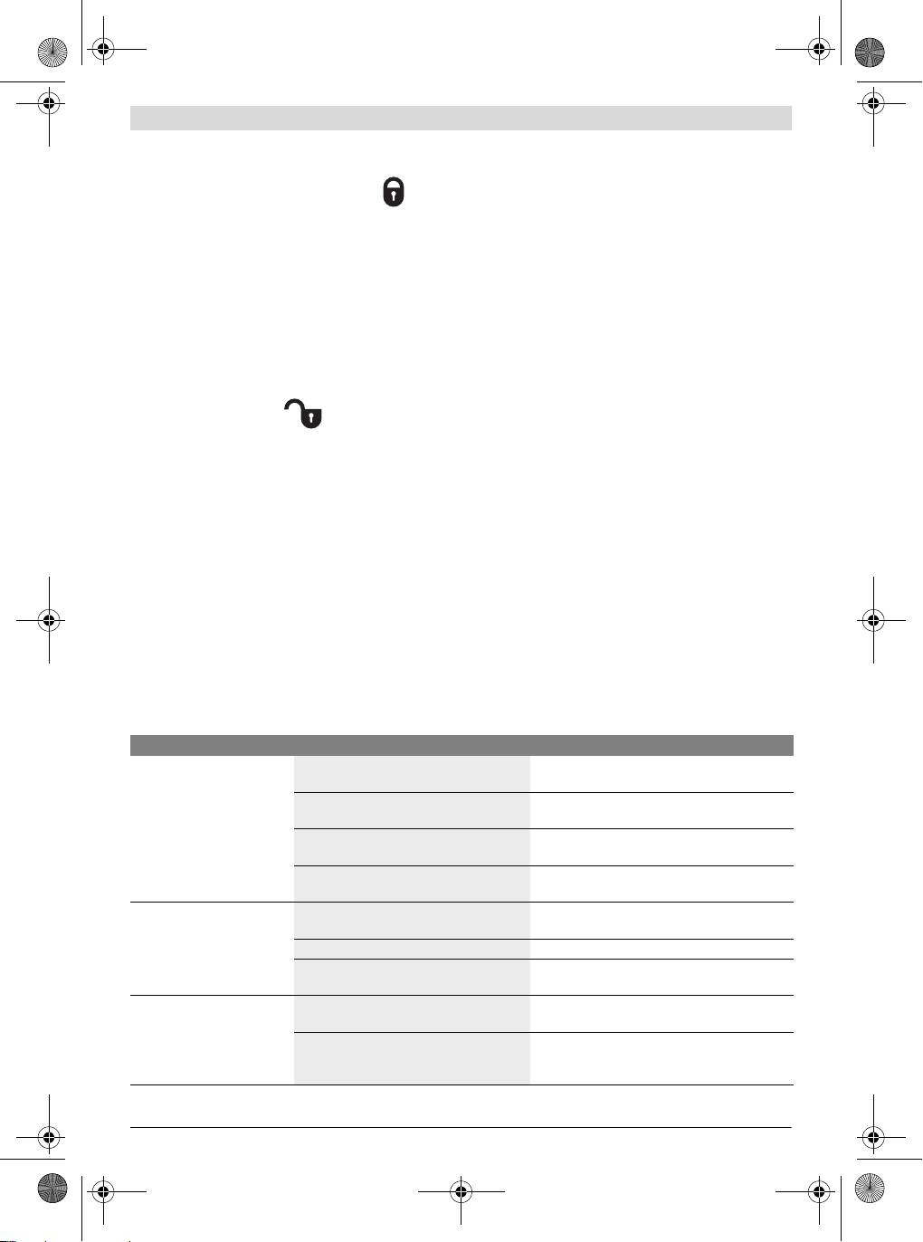
Symbol Meaning
f When operating the power tool in damp/moist environ-
f Wait until the rotor has come to a
ments is unavoidable, use a residual current device
complete stop. Touching a rotating
(RCD). Use of a residual current device reduces the risk of
rotor can lead to injuries.
electric shock.
f Do not use the power tool if the switch does not turn it
on and off. Any power tool that cannot be controlled with
the switch is dangerous and must be repaired.
Bosch Power Tools 2 609 005 736 | (16.1.12)

OBJ_BUCH-1513-003.book Page 16 Monday, January 16, 2012 11:29 AM
16 | English
Symbol Meaning
23 Pump lock
24 Pedestal
Adapting the height-adjustable paint-
bucket coupling to the height of the paint
25 Pump-hose connection
bucket:
26 Feed-hose connection on base unit
base unit must always stand level on the
27 Double-SDS-connector
flor.
28 Pump-hose holding clip
29 Height-adjustable paint-bucket coupling
Components for cleaning
leftward
30 Mixing-nozzle spanner
Pump lock engaged (pump
31 Water tap-adapter with gasket
function possible only in this
32 SDS connection on paint filter
position)
33 Pump hose
rightward
34 Bypass hose
Pump lock disengaged
35 Rotor
36 Paint distributor
Product Description and
37 Paint chamber
38 Distributor plate
Specifications
*Accessories shown or described are not part of the standard de-
Intended Use
livery scope of the product. A complete overview of accessories
can be found in our accessories program.
The machine is intended only for painting water-based disper-
sion wall paint.
Technical Data
Use the machine only when you can fully assess all functions
Electric Paint Roller PPR 250
and handle them without limitation, or after having received
Article number
3 603 BA0 0..
appropriate instructions.
Rated power input
W35
Product Features
Paint delivery capacity
ml/min 400
The numbering of the components shown refers to the repre-
Required time for application of
sentation of the power tool on the graphic pages.
2
paint on 2 m
min 1
1 Paint applicator extension
Length
2 Feed hose
– Paint applicator
cm
40
3 Paint applicator
– Paint applicator + extension
cm
120
4 Intake hose
– Feed hose
m
5
5 Base unit
Dimensions of paint roll
Paint applicator
–Width
cm
25
6 Remote control holder
– Shank diameter
mm
8
– Core diameter (incl. pile)
mm
45–50
7 Trigger switch
– Pile height
mm
11
8 Remote control (PaintControl system)
–Pile material
Polyester
9 Extension handle
Weight according to
10 Screw connection of extension
EPTA-Procedure 01/2003
kg 3.7
11 Paint applicator handle
Protection class
12 Guide groove for feed hose
–Base unit
IP X4 *
13 Feed-hose connection on paint applicator
– Trigger switch with remote
14 Bucket holder
control
IP X5 **
15 Roll holder
* Protection against water splash from all directions
16 Paint roll
** Protection against water jets from all directions
The values given are valid for a nominal voltage [U] of 230 V. For differ-
17 Roll axle
ent voltages and models for specific countries, these values can vary.
Base unit
Please observe the article number on the type plate of your machine.
18 On/Off switch
The trade names of the individual machines may vary.
19 Carrying handle
Noise Information
20 Pump lid
Typically the A-weighted sound pressure level of the product
21 Holding clamp
is less than 70 dB(A).
22 Paint filter
2 609 005 736 | (16.1.12) Bosch Power Tools

OBJ_BUCH-1513-003.book Page 17 Monday, January 16, 2012 11:29 AM
English | 17
Declaration of Conformity
– Cover or mask off floors, furnishings, door and window
frames, etc.
We declare under our sole responsibility that the product de-
– Also, sufficiently underlay the paint bucket and base unit
scribed under “Technical Data” is in conformity with the fol-
with covering-off material (foil, cardboard, etc.).
lowing standards or standardization documents: EN 60335,
EN 300 220-1:2006, EN 300 220-2:2007, EN 301 489-
Preparing the Paint
1:2008, EN 301 489-3:2002 according to the provisions of
– Prepare the paint according to the manufacturer’s instruc-
the directives 2011/65/EU, 2006/95/EC, 2004/108/EC,
tions.
1999/5/EC.
– Stir paint thoroughly and dilute as required.
11
When the painting result is not satisfactory or no paint comes
Dr. Egbert Schneider
Dr. Eckerhard Strötgen
out: See “Correction of Malfunctions”, page 18.
Senior Vice President
Engineering Director
Coupling the Base Unit and the Paint Bucket
Engineering
PT/ESI
(see figures C1–C2)
– Set down base unit 5 level on the floor next to the opened
paint bucket.
– Pull the height-adjustable paint-bucket coupling 29 up-
Robert Bosch GmbH, Power Tools Division
ward to the stop.
D-70745 Leinfelden-Echterdingen
– Hold the paint bucket handle upright and slide the hooks of
Leinfelden, 26.09.2011
the paint-bucket coupling down to the edge of the paint
bucket.
Assembly
The paint bucket handle must always be positioned be-
tween the hooks of the paint-bucket coupling.
f Before any work on the machine itself, pull the mains
– Insert the paint filter 22 to the bottom of the paint bucket.
plug.
– Fasten the intake hose 4 in the holding clip 28.
Unreel the Feed Hose (see figure A)
Starting Operation
– Open holding clamp 21 and completely unreel feed hose 2
f Observe correct mains voltage! The voltage of the pow-
from base unit 5.
er source must agree with the voltage specified on the
– Lock holding clamp 21 again.
nameplate of the machine. Power tools marked with
Note: When painting only with the paint applicator 3 (without
230 V can also be operated with 220 V.
extension 1), the feed hose 2 can be fastened in one of the
f Always place the base unit and the paint bucket on a
two exterior guide grooves 12 for more convenient working.
level surface. When operating the paint roller on a ladder
or an inclined surface, the base unit and the paint bucket
Mounting the Extension (see figures B1–B2)
can tip over or fall down. This can lead to injury and con-
– Screw the screw connection 10 of the extension into the
tamination from the coating material.
paint applicator 3.
f Do not cover off the base unit. Otherwise, a possible mal-
– Fasten feed hose 2 in the straight guide grooves 12 of
function cannot be detected.
paint applicator 3 and extension 1.
– Remove remote control 8 from paint applicator 3 and clip
f Keep other electrical machines/devices away while us-
it into holder 6 of extension 1.
ing the paint roller or cover them off adequately. Possi-
bly occurring paint splashes can lead to accidents and soil-
ing.
Operation
f Regularly provide for proper ventilation in the working
f Before any work on the machine itself, pull the mains
range and for sufficient fresh air throughout the com-
plug.
plete area.
f Wear safety glasses/goggles. This will protect your eyes
Preparing for Operation
against splashing or ejected paint.
f Working close to the edge of open waters or on neigh-
Wear appropriate work clothes. Paint is difficult to remove
bouring areas in the direct vicinity of open waters is not
from clothing.
permitted.
Prevent the hose system from being constricted, e. g.,
When purchasing paint, observe its environmental compati-
through crushing, kinking or pulling! Do not stand on the feed
bility.
hose 2.
Preparing the Surface to be Painted
Keep the hose system away from heat sources.
The surface to be painted must be clean, dry and free of
Do not pull the hoses. Especially when moving the base unit,
grease.
do not pull it by the feed hose 2. Carry the base unit only by
When working indoors, all non-covered surface can be soiled.
the carrying handle 19.
Therefore, thoroughly prepare the area around the surface to
be painted:
Bosch Power Tools 2 609 005 736 | (16.1.12)
OBJ_BUCH-1513-003.book Page 18 Monday, January 16, 2012 11:29 AM
18 | English
Switching On (see figure D)
Regulating the Paint Amount during Painting
– Plug the mains plug into a socket outlet.
The paint amount can be regulated with the trigger switch.
– Make sure that the pump lock 23 is engaged.
– Press the trigger switch 7 until the application of paint on
the paint roll is homogeneous.
–To start the machine, push the On/Off switch 18 to the “I”
– Afterwards, release the trigger switch until the application
position.
of paint on the painting surface is no longer opaque.
– Grasp the paint applicator 3 or extension 1 by the respec-
– Then, refill the paint chamber again with a sufficient
tive handle and direct the paint roll 16 toward the surface
amount of paint (press trigger switch 7 approx. 5 sec-
to be painted.
onds).
– Press the trigger switch 7 on the remote control 8.
Changing the Paint Roll (see figures E1 – E2)
Switching Off
Remove the paint roll from the paint applicator for cleaning or
– Release the trigger switch 7.
when the paint roll is worn.
–To switch off the machine, push the On/Off switch 18 to
– Pull the roll holders 15 apart and allow the paint roll 16 to
the “0” position.
slide out of the paint applicator 3.
– Pull the mains plug from the socket outlet.
– Disengage pump lock 23.
To prevent the paint-soaked paint roll from drying out until it
has been washed out, it is best to immerse it into a water
To relieve the lock tension, lightly push the pump lid 20 up-
bucket.
ward, if required.
Appropriate new paint rolls can be found in our Bosch acces-
sories program.
Working Advice
Paint rolls from other manufacturers can also be used, when
the respective dimensions are observed (see “Technical Da-
Painting
ta”, page 16).
Before painting, moisten new or dried paint rolls with water.
When the paint roll is new or dry, it takes approx. six lanes un-
Insert a new paint roll as follows:
til the paint application is homogeneous and without streaks.
– Pull the roll axle 17 out of the old paint roll 16 and slide the
new paint roll on the roll axle until centred.
Filling an empty feed hose takes approx. one minute.
– Insert the roll axle 17 on one side in the roll holder 15 until
– Press the trigger switch 7 to apply a sufficient amount of
it fits.
paint on the paint roll 16 and uniformly move the paint roll
– Press the paint roll into the roll holder of the other side.
up and down.
The paint roll must be able to rotate freely.
– Avoid interruptions within the surface to be painted.
Evenly guiding the paint roll will lead to a uniform surface
Placing Down the Paint Applicator (see figure F)
quality.
– Place down the paint applicator 3 on the edge of the paint
bucket so that it rests on the bucket holder 14.
Correction of Malfunctions
Problem Cause Corrective Measure
Paint application unsatis-
The hoses are obstructed. No or too little
Make sure that non of the hoses are squeezed or
factory.
paint being transported.
creased.
The paint is too viscous and therefore cannot
Stir paint thoroughly and dilute as required.
be transported.
The pump lock 23 is not engaged. Make sure that pump lid 20 is properly inserted
and locked.
The paint bucket is empty. Refill the paint bucket with fresh paint or ex-
change the empty paint bucket against a full one.
No paint coming out of paint
The paint is too viscous and cannot be drawn
Stir paint thoroughly and dilute as required.
applicator 3.
in by the pump.
The hoses are obstructed. Clean the hose system (see “Cleaning”, page19).
The hoses are obstructed. No or too little
Make sure that non of the hoses are squeezed or
paint being transported.
creased.
The remote control 8 is
The base unit is switched off. Switch the base unit on (see “"Switching
inoperative.
On"Switching On”, page18).
The remote control battery is empty. Contact an authorised service agent for Bosch
power tools.
Have the component replaced there.
2 609 005 736 | (16.1.12) Bosch Power Tools

OBJ_BUCH-1513-003.book Page 19 Monday, January 16, 2012 11:29 AM
English | 19
Maintenance and Service
Flushing the system:
– Carry the paint applicator
3, feed hose 2, pump lid 20 and
f Before any work on the machine itself, pull the mains
intake hose 4 to the prepared water tap.
plug.
Please note that paint may escape or leak from the system.
Cleaning
– Attach the double-SDS-connector 27 to adapter 31 on the
After painting, the system must be pumped empty and all
water tap.
paint-carrying parts must be cleaned.
– Hold the paint applicator 3 over a suitable collecting con-
tainer (e. g. a bucket).
There are two possibilities for cleaning the system:
– Carefully open the water tap and run lukewarm water
– EasyClean: Using universal connectors, the system is con-
through the system.
nected to a water tap and flushed.
– When flushing, lightly press pump hose 33 together sever-
– Alternative possibility: The system pumps fresh water
al times.
from a bucket for cleaning.
This will lead to better cleaning results.
Proper cleaning is a prerequisite for perfect operation of the
Additionally, this also cleans bypass hose 34, which pre-
electric paint roller. No warranty claims can be undertaken if
vents the rotor from overloading in case of excessive pres-
cleaning is not carried out or is carried out incorrectly.
sure in the hose system.
Keep the base unit, the holding clip 28 and the remote control
– Flush the system until only clear water comes out of the
8 clean. Clean them with a moist cloth. The base unit and the
paint applicator.
remote control may not be immersed into water.
– Clean the paint filter 22 and the intake hose 4 (connect
Always clean the paint roll, the paint applicator and the hose
SDS connection 32 to the water tap and flush; additional
system with water.
cleaning of paint filter with brush).
– Release the adapter 31 from the water tap and from the
Preparation
double-SDS-connector 27.
– Place down the paint applicator 3 on the edge of the paint
Screw the mixing nozzle back onto water tap.
bucket so that it rests on the bucket holder 14.
Cleaning the paint applicator and the paint roll:
– Loosen the double-SDS-connector 27 from the holding
– See “Cleaning the Paint Applicator and the Paint Roll”,
clip 28 and completely remove the intake hose 4 and the
page 20.
paint filter 22 from the paint bucket.
– Remove the paint roll 16 from the paint applicator 3 (see
Mounting together the dried components:
“Changing the Paint Roll”, page 18).
– Allow all components to dry thoroughly.
– Hold the paint applicator 3 above the paint bucket and
If possible, hang up the paint roll 16 to dry.
press the trigger switch 7 until the hose system is pumped
If the paint roll is placed down to dry, the pile will be de-
empty and no more paint comes out of the paint applica-
formed. This may lead to an uneven surface quality when
tor.
using the paint roller the next time.
– Release the trigger switch 7 and switch the power tool off.
– Reconnect the intake hose 4 to the SDS connection 32 on
– Pull the mains plug from the socket outlet.
the paint filter 22.
– Manually turn rotor 35 to the indicated position (see figure
EasyClean (see figures G1–G4)
G4) in order to avoid damage to pump hose 33 when in-
Note: Use only the supplied hoses and adapters for connect-
serting pump lid 20.
ing to the water supply.
– Reinsert the pump lid 20 into the housing opening and
Preparing the water tap:
push it upward to the stop.
– Unscrew the mixing nozzle from a water tap using the sup-
– Shut pump lock 23 until it engages.
plied mixing-nozzle spanner 30 or a suitable tool.
– Lock holding clamp 21 again.
– Screw the fitting adapter 31 (M22 or M24 thread) in or on
Alternative Cleaning Method (see figure H)
the water tap.
Note: This cleaning method takes somewhat longer than the
Additional water-tap adapters are available in the Bosch
EasyClean method.
accessories program.
– Couple base unit 5 to the water bucket (also see “Coupling
Separating paint-carrying components:
the Base Unit and the Paint Bucket”, page 17).
– Unlatch holding clamp 21.
– Insert paint filter 22 to the bottom of the water bucket.
– Disengage pump lock 23.
– Fasten the intake hose 4 in the holding clip 28.
– Plug the mains plug into a socket outlet.
To relieve the lock tension, lightly push the pump lid 20 up-
– Make sure that the pump lock 23 is engaged.
ward, if required.
– Push the pump lid 20 downward to the stop and then care-
–To start the machine, push the On/Off switch 18 to the “I”
fully lift it out of the housing opening of base unit 5.
position.
– Loosen the SDS connection 32 at the bottom part of the in-
– Hold paint applicator 3 over a suitable collecting container
take hose 4.
(e.g. a bucket) and actuate trigger switch 7 until only clear
water comes out of the paint applicator and no more paint
can be seen in the hoses (visual check).
Bosch Power Tools 2 609 005 736 | (16.1.12)

OBJ_BUCH-1513-003.book Page 20 Monday, January 16, 2012 11:29 AM
20 | English
Always lightly move the hoses.
After-sales Service and Customer Assistance
This will lead to better cleaning results.
Our after-sales service responds to your questions concern-
– Clean the paint applicator and the paint roll: See “Cleaning
ing maintenance and repair of your product as well as spare
the Paint Applicator and the Paint Roll”, page 20.
parts. Exploded views and information on spare parts can al-
– Allow all components to dry thoroughly.
so be found under: www.bosch-pt.com
If possible, hang up the paint roll 16 to dry.
Our customer service representatives can answer your ques-
If the paint roll is placed down to dry, the pile will be de-
tions concerning possible applications and adjustment of
formed. This may lead to an uneven surface quality when
products and accessories.
using the paint roller the next time.
Great Britain
Cleaning the Paint Applicator and the Paint Roll
Robert Bosch Ltd. (B.S.C.)
(see figures I1–I3)
P.O. Box 98
After flushing the system, some of the components still have
Broadwater Park
to be cleaned manually.
North Orbital Road
– Remove paint remainders from paint applicator 3 using a
Denham
brush.
Uxbridge
– Pull paint distributor 36 out of the paint chamber 37.
UB 9 5HJ
For easier cleaning, turn the paint distributor by 90°.
Tel. Service: +44 (0844) 736 0109
– Remove the distributor plate 38 from the paint distributor
Fax: +44 (0844) 736 0146
36.
E-Mail: boschservicecentre@bosch.com
For this, lift the distributor plate on one side and pull it lat-
Ireland
erally out of the retaining clamps.
– Remove paint remainders from of the distributor plate 38,
Origo Ltd.
the paint distributor 36 and from of the paint chamber 37
Unit 23 Magna Drive
using a small brush.
Magna Business Park
– Wash out the paint roll 16 thoroughly.
City West
Dublin 24
Storage
Tel. Service: +353 (01) 4 66 67 00
Before storing, the electric paint roller must be properly
Fax: +353 (01) 4 66 68 88
cleaned and all components dried.
Australia, New Zealand and Pacific Islands
– Slide distributor plate 38 laterally into the retaining clamps
Robert Bosch Australia Pty. Ltd.
in paint distributor 36.
Power Tools
– Clip paint distributor 36 into the paint chamber 37.
Locked Bag 66
– Wind up feed hose 2 around the base unit 5 and affix it with
Clayton South VIC 3169
holding clamp 21.
Customer Contact Center
– Slide down paint-bucket coupling 29 completely to the
Inside Australia:
bottom.
Phone: +61 (01300) 307 044
– Insert paint roll 16 into paint applicator 3 (see “Changing
Fax: +61 (01300) 307 045
the Paint Roll”, page 18).
Inside New Zealand:
Material Disposal
Phone: +64 (0800) 543 353
Paint and dried paint remainders must be disposed of in an
Fax: +64 (0800) 428 570
environmentally-friendly manner. Observe the manufactur-
Outside AU and NZ:
er’s instructions for disposal and the local regulations for haz-
Phone: +61 (03) 9541 5555
ardous waste disposal.
www.bosch.com.au
Chemicals harmful to the environment may not be disposed
Republic of South Africa
of into soil, groundwater or bodies of water. Never pour
Customer service
chemicals harmful to the environment into the sewerage sys-
Hotline: +27 (011) 6 51 96 00
tem!
Gauteng – BSC Service Centre
Maintenance
35 Roper Street, New Centre
If the replacement of the supply cord is necessary, this has to
Johannesburg
be done by Bosch or an authorized Bosch service agent in or-
Tel.: +27 (011) 4 93 93 75
der to avoid a safety hazard.
Fax: +27 (011) 4 93 01 26
If the machine should fail despite the care taken in manufac-
E-Mail: bsctools@icon.co.za
turing and testing procedures, repair should be carried out by
an after-sales service centre for Bosch power tools.
In all correspondence and spare parts order, please always in-
clude the 10-digit article number given on the type plate of
the machine.
2 609 005 736 | (16.1.12) Bosch Power Tools
