Bosch GSB 19-2 RE Professional: инструкция
Раздел: Электроинструменты
Тип: Дрель ударная
Характеристики, спецификации
Инструкция к Дрели ударной Bosch GSB 19-2 RE Professional
OBJ_BUCH-824-004.book Page 1 Wednesday, April 27, 2011 10:54 AM
Robert Bosch GmbH
Power Tools Division
70745 Leinfelden-Echterdingen
Germany
GSB Professional
www.bosch-pt.com
19-2 RE | 780
1 619 929 J12 (2011.04) PS / 173 UNI
de Originalbetriebsanleitung
el Ðñùôüôõðï ïäçãéþí ÷ñÞóçò
sr Originalno uputstvo za rad
en Original instructions
tr Orijinal işletme talimat
sl Izvirna navodila
fr Notice originale
pl Instrukcja oryginalna
hr Originalne upute za rad
es Manual original
cs Původní návod k používání
et Algupärane kasutusjuhend
pt Manual original
sk Pôvodný návod na použitie
lv Instrukcijas oriģinālvalodā
it Istruzioni originali
hu Eredeti használati utasítás
lt Originali instrukcija
nl Oorspronkelijke
ru Îðèãèíàëüíîå ðóêîâîäñòâî ïî
ar
ΕΎϤϴϠόΗϞϴϐθΘϟΔϴϠλϷ
gebruiksaanwijzing
ýêñïëóàòàöèè
fa
Ϡλ έΎ ίήσ ΎϤϨϫέ
da Original brugsanvisning
uk Îðèã³íàëüíà ³íñòðóêö³ÿ ç
sv Bruksanvisning i original
åêñïëóàòàö³¿
no Original driftsinstruks
ro Instrucţiuni originale
fi Alkuperäiset ohjeet
bg Îðèãèíàëíà èíñòðóêöèÿ
2 |
Deutsch. . . . . . . . . . . . . . . . . . . . . . . . . . . . . . . . . . . . . . . . . Seite 6
English . . . . . . . . . . . . . . . . . . . . . . . . . . . . . . . . . . . . . . . . . . Page 11
Français . . . . . . . . . . . . . . . . . . . . . . . . . . . . . . . . . . . . . . . . . Page 17
Español. . . . . . . . . . . . . . . . . . . . . . . . . . . . . . . . . . . . . . . . Página 23
Português . . . . . . . . . . . . . . . . . . . . . . . . . . . . . . . . . . . . . . Página 30
Italiano . . . . . . . . . . . . . . . . . . . . . . . . . . . . . . . . . . . . . . . . Pagina 35
Nederlands. . . . . . . . . . . . . . . . . . . . . . . . . . . . . . . . . . . . . Pagina 41
Dansk . . . . . . . . . . . . . . . . . . . . . . . . . . . . . . . . . . . . . . . . . . . Side 47
Svenska . . . . . . . . . . . . . . . . . . . . . . . . . . . . . . . . . . . . . . . . . Sida 53
Norsk. . . . . . . . . . . . . . . . . . . . . . . . . . . . . . . . . . . . . . . . . . . . Side 58
Suomi . . . . . . . . . . . . . . . . . . . . . . . . . . . . . . . . . . . . . . . . . . . Sivu 63
ÅëëçíéêÜ . . . . . . . . . . . . . . . . . . . . . . . . . . . . . . . . . . . . . . . Óåëßäá 68
Türkçe. . . . . . . . . . . . . . . . . . . . . . . . . . . . . . . . . . . . . . . . . . Sayfa 74
Polski . . . . . . . . . . . . . . . . . . . . . . . . . . . . . . . . . . . . . . . . . Strona 79
Česky . . . . . . . . . . . . . . . . . . . . . . . . . . . . . . . . . . . . . . . . . Strana 85
Slovensky . . . . . . . . . . . . . . . . . . . . . . . . . . . . . . . . . . . . . . Strana 91
Magyar . . . . . . . . . . . . . . . . . . . . . . . . . . . . . . . . . . . . . . . . . Oldal 97
Ðóññêèé . . . . . . . . . . . . . . . . . . . . . . . . . . . . . . . . . . . . . Ñòðàíèöà 103
Óêðà¿íñüêà . . . . . . . . . . . . . . . . . . . . . . . . . . . . . . . . . . . Ñòîð³íêà 109
Română. . . . . . . . . . . . . . . . . . . . . . . . . . . . . . . . . . . . . . . . Pagina 115
Áúëãàðñêè. . . . . . . . . . . . . . . . . . . . . . . . . . . . . . . . . . . . Ñòðàíèöà 121
Srpski . . . . . . . . . . . . . . . . . . . . . . . . . . . . . . . . . . . . . . . . . Strana 127
Slovensko . . . . . . . . . . . . . . . . . . . . . . . . . . . . . . . . . . . . . . . Stran 133
Hrvatski. . . . . . . . . . . . . . . . . . . . . . . . . . . . . . . . . . . . . . . Stranica 138
Eesti . . . . . . . . . . . . . . . . . . . . . . . . . . . . . . . . . . . . . . . . Lehekülg 143
Latviešu . . . . . . . . . . . . . . . . . . . . . . . . . . . . . . . . . . . . . . Lappuse 149
Lietuviškai. . . . . . . . . . . . . . . . . . . . . . . . . . . . . . . . . . . . . Puslapis 155
. . . . . . . . . . . . . . . . . . . . . . . . . . . . . . . . . . . . 166
. . . . . . . . . . . . . . . . . . . . . . . . . . . . . . . . . . . 172
1 619 929 J12 | (27.4.11) Bosch Power Tools
v
v
v
v
OBJ_BUCH-824-004.book Page 2 Wednesday, April 27, 2011 10:54 AM
cc
cc
ΔΤϔλ
vÝ—U
ϪΤϔλ

OBJ_BUCH-824-004.book Page 3 Wednesday, April 27, 2011 10:54 AM
3 |
2 608 180 009
GSB 19-2 RE:
(DP 500)
2 608 572 149
GSB 780:
2 608 572 105
2 608 030 053
GSB 19-2 RE:
(MS 65)
2 608 571 067
2 608 030 055
(MS 80)
2 607 990 050
(S 41)
2 602 025 190
1 613 001 010
1 619 929 J12 | (27.4.11) Bosch Power Tools
OBJ_BUCH-824-004.book Page 4 Wednesday, April 27, 2011 10:54 AM
4 |
2
1
3
4
5
6
7
9
8
10
GSB 19-2 RE
8
Professional
BA
1
98
1 619 929 J12 | (27.4.11) Bosch Power Tools
OBJ_BUCH-824-004.book Page 5 Wednesday, April 27, 2011 10:54 AM
5 |
13
DC
12
11
14
E
F
16
15
17 1
G
H
3
3
17
1
1 619 929 J12 | (27.4.11) Bosch Power Tools
OBJ_BUCH-824-004.book Page 6 Wednesday, April 27, 2011 10:54 AM
6 | Deutsch
f Wenn der Betrieb des Elektrowerkzeuges in feuchter
Deutsch
Umgebung nicht vermeidbar ist, verwenden Sie einen
Fehlerstromschutzschalter. Der Einsatz eines Fehler-
stromschutzschalters vermindert das Risiko eines elektri-
Sicherheitshinweise
schen Schlages.
Allgemeine Sicherheitshinweise für
Sicherheit von Personen
Elektrowerkzeuge
f Seien Sie aufmerksam, achten Sie darauf, was Sie tun,
und gehen Sie mit Vernunft an die Arbeit mit einem
Lesen Sie alle Sicherheitshinweise
WARNUNG
Elektrowerkzeug. Benutzen Sie kein Elektrowerkzeug,
und Anweisungen. Versäumnisse bei
wenn Sie müde sind oder unter dem Einfluss von Dro-
der Einhaltung der Sicherheitshinweise und Anweisungen
gen, Alkohol oder Medikamenten stehen. Ein Moment
können elektrischen Schlag, Brand und/oder schwere Verlet-
der Unachtsamkeit beim Gebrauch des Elektrowerkzeuges
zungen verursachen.
kann zu ernsthaften Verletzungen führen.
Bewahren Sie alle Sicherheitshinweise und Anweisungen
f Tragen Sie persönliche Schutzausrüstung und immer
für die Zukunft auf.
eine Schutzbrille. Das Tragen persönlicher Schutzausrüs-
Der in den Sicherheitshinweisen verwendete Begriff „Elektro-
tung, wie Staubmaske, rutschfeste Sicherheitsschuhe,
werkzeug“ bezieht sich auf netzbetriebene Elektrowerkzeuge
Schutzhelm oder Gehörschutz, je nach Art und Einsatz des
(mit Netzkabel) und auf akkubetriebene Elektrowerkzeuge
Elektrowerkzeuges, verringert das Risiko von Verletzun-
(ohne Netzkabel).
gen.
Arbeitsplatzsicherheit
f Vermeiden Sie eine unbeabsichtigte Inbetriebnahme.
f Halten Sie Ihren Arbeitsbereich sauber und gut be-
Vergewissern Sie sich, dass das Elektrowerkzeug aus-
leuchtet. Unordnung oder unbeleuchtete Arbeitsbereiche
geschaltet ist, bevor Sie es an die Stromversorgung
können zu Unfällen führen.
und/oder den Akku anschließen, es aufnehmen oder
f Arbeiten Sie mit dem Elektrowerkzeug nicht in explosi-
tragen. Wenn Sie beim Tragen des Elektrowerkzeuges den
onsgefährdeter Umgebung, in der sich brennbare Flüs-
Finger am Schalter haben oder das Gerät eingeschaltet an
sigkeiten, Gase oder Stäube befinden. Elektrowerkzeu-
die Stromversorgung anschließen, kann dies zu Unfällen
ge erzeugen Funken, die den Staub oder die Dämpfe
führen.
entzünden können.
f Entfernen Sie Einstellwerkzeuge oder Schrauben-
f Halten Sie Kinder und andere Personen während der
schlüssel, bevor Sie das Elektrowerkzeug einschalten.
Benutzung des Elektrowerkzeugs fern. Bei Ablenkung
Ein Werkzeug oder Schlüssel, der sich in einem drehenden
können Sie die Kontrolle über das Gerät verlieren.
Geräteteil befindet, kann zu Verletzungen führen.
f Vermeiden Sie eine abnormale Körperhaltung. Sorgen
Elektrische Sicherheit
Sie für einen sicheren Stand und halten Sie jederzeit
f Der Anschlussstecker des Elektrowerkzeuges muss in
das Gleichgewicht. Dadurch können Sie das Elektrowerk-
die Steckdose passen. Der Stecker darf in keiner Weise
zeug in unerwarteten Situationen besser kontrollieren.
verändert werden. Verwenden Sie keine Adapterste-
f Tragen Sie geeignete Kleidung. Tragen Sie keine weite
cker gemeinsam mit schutzgeerdeten Elektrowerkzeu-
Kleidung oder Schmuck. Halten Sie Haare, Kleidung
gen. Unveränderte Stecker und passende Steckdosen ver-
und Handschuhe fern von sich bewegenden Teilen. Lo-
ringern das Risiko eines elektrischen Schlages.
ckere Kleidung, Schmuck oder lange Haare können von
f Vermeiden Sie Körperkontakt mit geerdeten Oberflä-
sich bewegenden Teilen erfasst werden.
chen wie von Rohren, Heizungen, Herden und Kühl-
f Wenn Staubabsaug- und -auffangeinrichtungen mon-
schränken. Es besteht ein erhöhtes Risiko durch elektri-
tiert werden können, vergewissern Sie sich, dass diese
schen Schlag, wenn Ihr Körper geerdet ist.
angeschlossen sind und richtig verwendet werden. Ver-
f Halten Sie Elektrowerkzeuge von Regen oder Nässe
wendung einer Staubabsaugung kann Gefährdungen
fern. Das Eindringen von Wasser in ein Elektrowerkzeug
durch Staub verringern.
erhöht das Risiko eines elektrischen Schlages.
Verwendung und Behandlung des Elektrowerkzeuges
f Zweckentfremden Sie das Kabel nicht, um das Elektro-
werkzeug zu tragen, aufzuhängen oder um den Stecker
f Überlasten Sie das Gerät nicht. Verwenden Sie für Ihre
aus der Steckdose zu ziehen. Halten Sie das Kabel fern
Arbeit das dafür bestimmte Elektrowerkzeug. Mit dem
von Hitze, Öl, scharfen Kanten oder sich bewegenden
passenden Elektrowerkzeug arbeiten Sie besser und si-
Geräteteilen. Beschädigte oder verwickelte Kabel erhö-
cherer im angegebenen Leistungsbereich.
hen das Risiko eines elektrischen Schlages.
f Benutzen Sie kein Elektrowerkzeug, dessen Schalter
f Wenn Sie mit einem Elektrowerkzeug im Freien arbei-
defekt ist. Ein Elektrowerkzeug, das sich nicht mehr ein-
ten, verwenden Sie nur Verlängerungskabel, die auch
oder ausschalten lässt, ist gefährlich und muss repariert
für den Außenbereich geeignet sind. Die Anwendung ei-
werden.
nes für den Außenbereich geeigneten Verlängerungska-
f Ziehen Sie den Stecker aus der Steckdose und/oder
bels verringert das Risiko eines elektrischen Schlages.
entfernen Sie den Akku, bevor Sie Geräteeinstellungen
vornehmen, Zubehörteile wechseln oder das Gerät
1 619 929 J12 | (27.4.11) Bosch Power Tools
OBJ_BUCH-824-004.book Page 7 Wednesday, April 27, 2011 10:54 AM
Deutsch | 7
weglegen. Diese Vorsichtsmaßnahme verhindert den un-
f Warten Sie, bis das Elektrowerkzeug zum Stillstand ge-
beabsichtigten Start des Elektrowerkzeuges.
kommen ist, bevor Sie es ablegen. Das Einsatzwerkzeug
f Bewahren Sie unbenutzte Elektrowerkzeuge außer-
kann sich verhaken und zum Verlust der Kontrolle über das
halb der Reichweite von Kindern auf. Lassen Sie Perso-
Elektrowerkzeug führen.
nen das Gerät nicht benutzen, die mit diesem nicht ver-
traut sind oder diese Anweisungen nicht gelesen
haben. Elektrowerkzeuge sind gefährlich, wenn sie von
Produkt- und Leistungsbeschreibung
unerfahrenen Personen benutzt werden.
f Pflegen Sie Elektrowerkzeuge mit Sorgfalt. Kontrollie-
Lesen Sie alle Sicherheitshinweise und An-
ren Sie, ob bewegliche Teile einwandfrei funktionieren
weisungen. Versäumnisse bei der Einhaltung
und nicht klemmen, ob Teile gebrochen oder so be-
der Sicherheitshinweise und Anweisungen
schädigt sind, dass die Funktion des Elektrowerkzeu-
können elektrischen Schlag, Brand und/oder
ges beeinträchtigt ist. Lassen Sie beschädigte Teile vor
schwere Verletzungen verursachen.
dem Einsatz des Gerätes reparieren. Viele Unfälle haben
Bitte klappen Sie die Aufklappseite mit der Darstellung des
ihre Ursache in schlecht gewarteten Elektrowerkzeugen.
Elektrowerkzeugs auf, und lassen Sie diese Seite aufgeklappt,
f Halten Sie Schneidwerkzeuge scharf und sauber. Sorg-
während Sie die Betriebsanleitung lesen.
fältig gepflegte Schneidwerkzeuge mit scharfen Schneid-
Bestimmungsgemäßer Gebrauch
kanten verklemmen sich weniger und sind leichter zu füh-
ren.
Das Elektrowerkzeug ist bestimmt zum Schlagbohren in Zie-
gel, Beton und Gestein, sowie zum Bohren in Holz, Metall, Ke-
f Verwenden Sie Elektrowerkzeug, Zubehör, Einsatz-
ramik und Kunststoff. Geräte mit elektronischer Regelung und
werkzeuge usw. entsprechend diesen Anweisungen.
Rechts-/Linkslauf sind auch geeignet zum Schrauben und Ge-
Berücksichtigen Sie dabei die Arbeitsbedingungen und
windeschneiden.
die auszuführende Tätigkeit. Der Gebrauch von Elektro-
werkzeugen für andere als die vorgesehenen Anwendun-
Abgebildete Komponenten
gen kann zu gefährlichen Situationen führen.
Die Nummerierung der abgebildeten Komponenten bezieht
Service
sich auf die Darstellung des Elektrowerkzeuges auf der Gra-
f Lassen Sie Ihr Elektrowerkzeug nur von qualifiziertem
fikseite.
Fachpersonal und nur mit Original-Ersatzteilen repa-
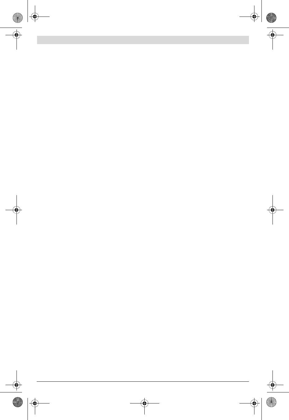
1 Schnellspannbohrfutter
rieren. Damit wird sichergestellt, dass die Sicherheit des
2 Umschalter „Bohren/Schlagbohren“
Elektrowerkzeuges erhalten bleibt.
3 Drehrichtungsumschalter
Sicherheitshinweise für Bohrmaschinen
4 Feststelltaste für Ein-/Ausschalter
f Tragen Sie Gehörschutz beim Schlagbohren. Die Einwir-
5 Stellrad Drehzahlvorwahl
kung von Lärm kann Gehörverlust bewirken.
6 Ein-/Ausschalter
f Benutzen Sie mit dem Gerät gelieferte Zusatzhandgrif-
7 Gangwahlschalter
fe. Der Verlust der Kontrolle kann zu Verletzungen führen.
8 Zusatzgriff (isolierte Grifffläche)*
f Halten Sie das Gerät an den isolierten Griffflächen,
9 Tiefenanschlag*
wenn Sie Arbeiten ausführen, bei denen das Einsatz-
10 Handgriff (isolierte Grifffläche)
werkzeug oder die Schraube verborgene Stromleitun-
11 Vordere Hülse*
gen oder das eigene Netzkabel treffen kann. Der Kon-
12 Hintere Hülse*
takt mit einer spannungsführenden Leitung kann auch
metallene Geräteteile unter Spannung setzen und zu ei-
13 Bohrfutterschlüssel*
nem elektrischen Schlag führen.
14 Zahnkranzbohrfutter*
f Verwenden Sie geeignete Suchgeräte, um verborgene
15 Schrauberbit*
Versorgungsleitungen aufzuspüren, oder ziehen Sie
16 Universalbithalter*
die örtliche Versorgungsgesellschaft hinzu. Kontakt mit
17 Innensechskantschlüssel *
Elektroleitungen kann zu Feuer und elektrischem Schlag
*Abgebildetes oder beschriebenes Zubehör gehört nicht zum
führen. Beschädigung einer Gasleitung kann zur Explosion
Standard-Lieferumfang. Das vollständige Zubehör finden Sie in
führen. Eindringen in eine Wasserleitung verursacht Sach-
unserem Zubehörprogramm.
beschädigung.
f Halten Sie das Elektrowerkzeug beim Arbeiten fest mit
beiden Händen und sorgen Sie für einen sicheren
Stand. Das Elektrowerkzeug wird mit zwei Händen siche-
rer geführt.
f Sichern Sie das Werkstück. Ein mit Spannvorrichtungen
oder Schraubstock festgehaltenes Werkstück ist sicherer
gehalten als mit Ihrer Hand.
Bosch Power Tools 1 619 929 J12 | (27.4.11)
OBJ_BUCH-824-004.book Page 8 Wednesday, April 27, 2011 10:54 AM
8 | Deutsch
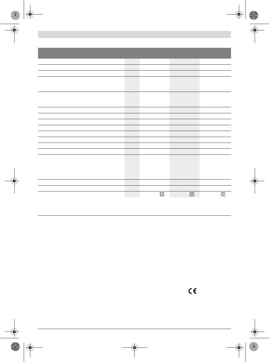
Technische Daten
Schlagbohrmaschine GSB 19-2 RE
GSB 19-2 RE
GSB 780
Professional
Professional
Professional
Sachnummer
3 601 A7B 5.. 3 601 A7B 6.. 3 601 A7B 1..
Nennaufnahmeleistung
W850850 780
Abgabeleistung
W430430 390
Leerlaufdrehzahl
-1
– 1. Gang
min
0–1000
0–1000
0–1000
-1
– 2. Gang
min
0–3000
0–3000
0–3000
Nenndrehzahl
-1
– 1. Gang
min
800
800
850
-1
– 2. Gang
min
2060
2060
2170
-1
Schlagzahl bei Leerlaufdrehzahl
min
51000 51000 51000
Nenndrehmoment (1./2. Gang)
Nm 5,2/2,0 5,2/2,0 4,1/1,6
Drehzahlvorwahl
z zz
Rechts-/Linkslauf
z zz
Zahnkranzbohrfutter
– z –
Schnellspannbohrfutter
z – z
Vollautomatische Spindelarretierung (Auto-Lock)
z ––
Spindelhalsdurchmesser
mm 43 43 43
max. Bohr-Ø (1./2. Gang)
–Beton
mm
18/13
18/13
18/13
– Mauerwerk
mm
20/15
20/15
20/15
–Stahl
mm
13/8
13/8
13/8
–Holz
mm
40/25
40/25
40/25
Bohrfutterspannbereich
mm 1,5 –13 1,5 – 13 1,5 – 13
Gewicht entsprechend EPTA-Procedure 01/2003
kg 2,6 2,6 2,6
Schutzklasse
/II /II /II
Die Angaben gelten für eine Nennspannung [U] von 230 V. Bei abweichenden Spannungen und in länderspezifischen Ausführungen können diese An-
gaben variieren.
Bitte beachten Sie die Sachnummer auf dem Typenschild Ihres Elektrowerkzeugs. Die Handelsbezeichnungen einzelner Elektrowerkzeuge können va-
riieren.
Geräusch-/Vibrationsinformation
weichenden Einsatzwerkzeugen oder ungenügender Wartung
eingesetzt wird, kann der Schwingungspegel abweichen.
Messwerte für Geräusch ermittelt entsprechend EN 60745.
Dies kann die Schwingungsbelastung über den gesamten Ar-
Der A-bewertete Geräuschpegel des Elektrowerkzeugs be-
beitszeitraum deutlich erhöhen.
trägt typischerweise: Schalldruckpegel 95 dB(A); Schallleis-
Für eine genaue Abschätzung der Schwingungsbelastung soll-
tungspegel 106 dB(A). Unsicherheit K=3 dB.
ten auch die Zeiten berücksichtigt werden, in denen das Ge-
Gehörschutz tragen!
rät abgeschaltet ist oder zwar läuft, aber nicht tatsächlich im
Schwingungsgesamtwerte a
h
(Vektorsumme dreier Richtun-
Einsatz ist. Dies kann die Schwingungsbelastung über den ge-
gen) und Unsicherheit K ermittelt entsprechend EN 60745:
samten Arbeitszeitraum deutlich reduzieren.
2
2
Bohren in Metall: a
h
=3,0m/s
, K=1,5 m/s
,
Legen Sie zusätzliche Sicherheitsmaßnahmen zum Schutz
2
2
Schlagbohren in Beton: a
h
=15m/s
, K=2,0 m/s
,
des Bedieners vor der Wirkung von Schwingungen fest wie
2
2
Schrauben: a
h
<2,5m/s
, K=1,5 m/s
,
zum Beispiel: Wartung von Elektrowerkzeug und Einsatzwerk-
2
2
Gewindeschneiden: a
h
<2,5m/s
, K=1,5 m/s
.
zeugen, Warmhalten der Hände, Organisation der Arbeitsab-
Der in diesen Anweisungen angegebene Schwingungspegel
läufe.
ist entsprechend einem in EN 60745 genormten Messverfah-
ren gemessen worden und kann für den Vergleich von Elektro-
Konformitätserklärung
werkzeugen miteinander verwendet werden. Er eignet sich
Wir erklären in alleiniger Verantwortung, dass das unter
auch für eine vorläufige Einschätzung der Schwingungsbelas-
„Technische Daten“ beschriebene Produkt mit den folgenden
tung.
Normen oder normativen Dokumenten übereinstimmt:
Der angegebene Schwingungspegel repräsentiert die haupt-
EN 60745 gemäß den Bestimmungen der Richtlinien
sächlichen Anwendungen des Elektrowerkzeugs. Wenn aller-
2004/108/EG, 2006/42/EG.
dings das Elektrowerkzeug für andere Anwendungen, mit ab-
1 619 929 J12 | (27.4.11) Bosch Power Tools
OBJ_BUCH-824-004.book Page 9 Wednesday, April 27, 2011 10:54 AM
Deutsch | 9
Technische Unterlagen bei:
Die Verriegelung löst sich wieder, wenn Sie zum Entfernen
Robert Bosch GmbH, PT/ESC,
des Werkzeuges die Hülse in Gegenrichtung drehen.
D-70745 Leinfelden-Echterdingen
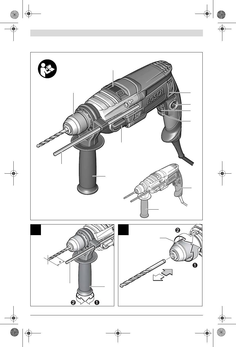
Schnellspannbohrfutter (GSB 780) (siehe Bild C)
Dr. Egbert Schneider
Dr. Eckerhard Strötgen
Halten Sie die hintere Hülse 12 des Schnellspannbohrfutters
Senior Vice President
Head of Product
1 fest und drehen Sie die vordere Hülse 11 in Drehrichtung
Engineering
Certification
n, bis das Werkzeug eingesetzt werden kann. Setzen Sie das
Werkzeug ein.
Halten Sie die hintere Hülse 12 des Schnellspannbohrfutters
1 fest und drehen Sie die vordere Hülse 11 in Drehrichtung o
Robert Bosch GmbH, Power Tools Division
von Hand kräftig zu, bis kein Überrasten mehr hörbar ist. Das
D-70745 Leinfelden-Echterdingen
Bohrfutter wird dadurch automatisch verriegelt.
18.02.2010
Die Verriegelung löst sich wieder, wenn Sie zum Entfernen
des Werkzeuges die vordere Hülse 11 in Gegenrichtung dre-
Montage
hen.
f Ziehen Sie vor allen Arbeiten am Elektrowerkzeug den
Zahnkranzbohrfutter (siehe Bild D)
Netzstecker aus der Steckdose.
Öffnen Sie das Zahnkranzbohrfutter 14 durch Drehen, bis
das Werkzeug eingesetzt werden kann. Setzen Sie das Werk-
Zusatzgriff (siehe Bild A)
zeug ein.
f Verwenden Sie Ihr Elektrowerkzeug nur mit dem Zu-
Stecken Sie den Bohrfutterschlüssel 13 in die entsprechen-
satzgriff 8.
den Bohrungen des Zahnkranzbohrfutters 14 und spannen
Sie können den Zusatzgriff 8 in 12 Positionen verstellen, um
Sie das Werkzeug gleichmäßig fest.
eine sichere und ermüdungsarme Arbeitshaltung zu errei-
Schraubwerkzeuge (siehe BildE)
chen.
Bei der Verwendung von Schrauberbits 15 sollten Sie immer
Drehen Sie das untere Griffstück des Zusatzgriffs 8 in Dreh-
einen Universalbithalter 16 benutzen. Verwenden Sie nur
richtung n und schieben Sie den Zusatzgriff 8 soweit nach
zum Schraubenkopf passende Schrauberbits.
vorn, bis Sie ihn in die gewünschte Position schwenken kön-
nen. Danach ziehen Sie den Zusatzgriff 8 wieder zurück und
Zum Schrauben stellen Sie den Umschalter „Bohren/Schlag-
drehen das untere Griffstück in Drehrichtung o wieder fest.
bohren“ 2 immer auf das Symbol „Bohren“.
Bohrtiefe einstellen (siehe Bild A)
Bohrfutter wechseln
Mit dem Tiefenanschlag 9 kann die gewünschte Bohrtiefe X
f Ziehen Sie vor allen Arbeiten am Elektrowerkzeug den
festgelegt werden.
Netzstecker aus der Steckdose.
Drehen Sie das untere Griffstück des Zusatzgriffs 8 entgegen
Bohrfutter demontieren (siehe Bild F)
dem Uhrzeigersinn und setzen Sie den Tiefenanschlag 9 ein.
Demontieren Sie den Zusatzgriff und bringen Sie den Gang-
Ziehen Sie den Tiefenanschlag so weit heraus, dass der Ab-
wahlschalter 7 in die Mittelstellung zwischen 1. und 2. Gang.
stand zwischen der Spitze des Bohrers und der Spitze des
Führen Sie einen Stahlstift Ø 4 mm mit ca. 50 mm Länge in
Tiefenanschlags der gewünschten Bohrtiefe X entspricht.
die Bohrung am Spindelhals ein, um die Bohrspindel zu arre-
Drehen Sie danach das untere Griffstück des Zusatzgriffs 8 im
tieren.
Uhrzeigersinn wieder fest.
Spannen Sie einen Innensechskantschlüssel 17 mit dem kur-
Die Riffelung am Tiefenanschlag 9 muss nach oben zeigen.
zen Schaft voran in das Schnellspannbohrfutter 1 ein.
Werkzeugwechsel
Legen Sie das Elektrowerkzeug auf eine standfeste Unterlage,
z. B. eine Werkbank. Halten Sie das Elektrowerkzeug fest und
f Tragen Sie beim Werkzeugwechsel Schutzhandschu-
lösen Sie das Schnellspannbohrfutter 1 durch Drehen des In-
he. Das Bohrfutter kann sich bei längeren Arbeitsvorgän-
nensechskantschlüssels 17 in Drehrichtung n. Ein festsit-
gen stark erwärmen.
zendes Schnellspannbohrfutter wird durch einen leichten
Schnellspannbohrfutter (GSB 19-2 RE) (siehe Bild B)
Schlag auf den langen Schaft des Innensechskantschlüssels
Bei nicht gedrücktem Ein-/Ausschalter 6 wird die Bohrspindel
17 gelöst. Entfernen Sie den Innensechskantschlüssel aus
arretiert. Dies ermöglicht ein schnelles, bequemes und einfa-
dem Schnellspannbohrfutter und schrauben Sie das Schnell-
ches Wechseln des Einsatzwerkzeuges im Bohrfutter.
spannbohrfutter vollständig ab.
Öffnen Sie das Schnellspannbohrfutter 1 durch Drehen in
Bei Elektrowerkzeugen mit Zahnkranzbohrfutter erfolgt die
Drehrichtung n, bis das Werkzeug eingesetzt werden kann.
Demontage sinngemäß wie oben beschrieben.
Setzen Sie das Werkzeug ein.
Bei Elektrowerkzeugen mit Schnellspannbohrfutter kann an-
Drehen Sie die Hülse des Schnellspannbohrfutters 1 in Dreh-
statt des Innensechskantschlüssels ein Gabelschlüssel
richtung o von Hand kräftig zu, bis kein Überrasten mehr hör-
(Schlüsselweite 19 mm) auf das Bohrfutter aufgesetzt wer-
bar ist. Das Bohrfutter wird dadurch automatisch verriegelt.
den.
Bosch Power Tools 1 619 929 J12 | (27.4.11)
OBJ_BUCH-824-004.book Page 10 Wednesday, April 27, 2011 10:54 AM
10 | Deutsch
Bohrfutter montieren (siehe Bild G)
Schlagbohren
Die Montage des Schnellspann-/Zahnkranzbohrfutters er-
Stellen Sie den Umschalter 2 auf das Symbol
folgt in umgekehrter Reihenfolge.
„Schlagbohren“.
f Entfernen Sie nach erfolgter Montage des Bohrfutters
den Stahlstift wieder aus der Bohrung.
Der Umschalter 2 rastet spürbar ein und kann auch bei laufen-
Das Bohrfutter muss mit einem Anzugsdrehmo-
dem Motor betätigt werden.
ment von ca. 50–55 Nm festgezogen werden.
Mechanische Gangwahl
f Sie können den Gangwahlschalter 7 bei langsam lau-
Staub-/Späneabsaugung
fendem Elektrowerkzeug betätigen. Dies sollte jedoch
nicht bei Stillstand, voller Belastung oder maximaler
f Stäube von Materialien wie bleihaltigem Anstrich, einigen
Drehzahl erfolgen.
Holzarten, Mineralien und Metall können gesundheits-
Mit dem Gangwahlschalter 7 können 2 Drehzahlbereiche vor-
schädlich sein. Berühren oder Einatmen der Stäube kön-
gewählt werden.
nen allergische Reaktionen und/oder Atemwegserkran-
kungen des Benutzers oder in der Nähe befindlicher
Gang I:
Personen hervorrufen.
Niedriger Drehzahlbereich; zum Arbeiten
Bestimmte Stäube wie Eichen- oder Buchenstaub gelten
mit großem Bohrdurchmesser oder zum
als krebserzeugend, besonders in Verbindung mit Zusatz-
Schrauben.
stoffen zur Holzbehandlung (Chromat, Holzschutzmittel).
Gang II:
Asbesthaltiges Material darf nur von Fachleuten bearbeitet
Hoher Drehzahlbereich; zum Arbeiten mit
werden.
kleinem Bohrdurchmesser.
– Sorgen Sie für gute Belüftung des Arbeitsplatzes.
– Es wird empfohlen, eine Atemschutzmaske mit Filter-
Lässt sich der Gangwahlschalter 7 nicht bis zum Anschlag
klasse P2 zu tragen.
schwenken, drehen Sie die Antriebsspindel mit dem Bohrer
Beachten Sie in Ihrem Land gültige Vorschriften für die zu
etwas.
bearbeitenden Materialien.
f Vermeiden Sie Staubansammlungen am Arbeitsplatz.
Ein-/Ausschalten
Stäube können sich leicht entzünden.
Drücken Sie zur Inbetriebnahme des Elektrowerkzeuges den
Ein-/Ausschalter 6 und halten Sie ihn gedrückt.
Betrieb
Zum Feststellen des gedrückten Ein-/Ausschalters 6 drü-
cken Sie die Feststelltaste 4.
Inbetriebnahme
Um das Elektrowerkzeug auszuschalten, lassen Sie den
f Beachten Sie die Netzspannung! Die Spannung der
Ein-/Ausschalter 6 los bzw. wenn er mit der Feststelltaste 4
Stromquelle muss mit den Angaben auf dem Typen-
arretiert ist, drücken Sie den Ein-/Ausschalter 6 kurz und las-
schild des Elektrowerkzeuges übereinstimmen. Mit
sen ihn dann los.
230 V gekennzeichnete Elektrowerkzeuge können
Überlastkupplung
auch an 220 V betrieben werden.
Um hohe Reaktionsmomente zu begrenzen, ist das Elektro-
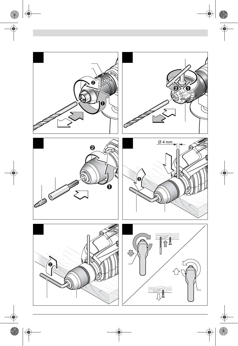
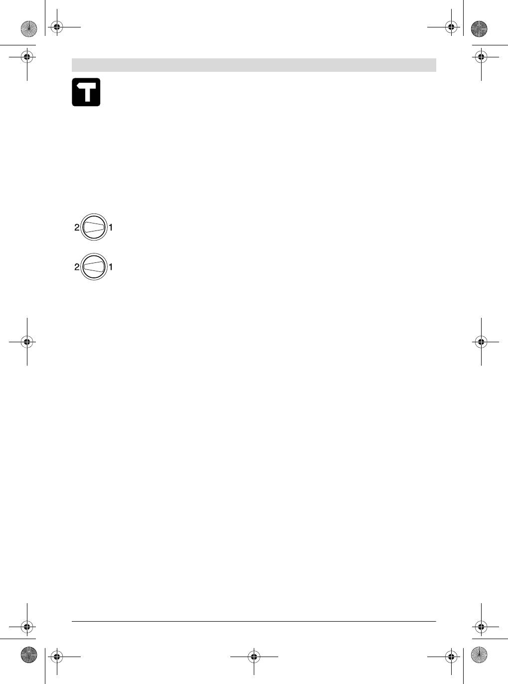
Drehrichtung einstellen (siehe Bild H)
werkzeug mit einer Überlastkupplung (Anti-Rotation) ausge-
f Betätigen Sie den Drehrichtungsumschalter 3 nur bei
stattet.
Stillstand des Elektrowerkzeuges.
f Klemmt oder hakt das Einsatzwerkzeug, wird der An-
Mit dem Drehrichtungsumschalter 3 können Sie die Drehrich-
trieb zur Bohrspindel unterbrochen. Halten Sie, wegen
tung des Elektrowerkzeuges ändern. Bei gedrücktem
der dabei auftretenden Kräfte, das Elektrowerkzeug
Ein-/Ausschalter 6 ist dies jedoch nicht möglich.
immer mit beiden Händen gut fest und nehmen Sie ei-
nen festen Stand ein.
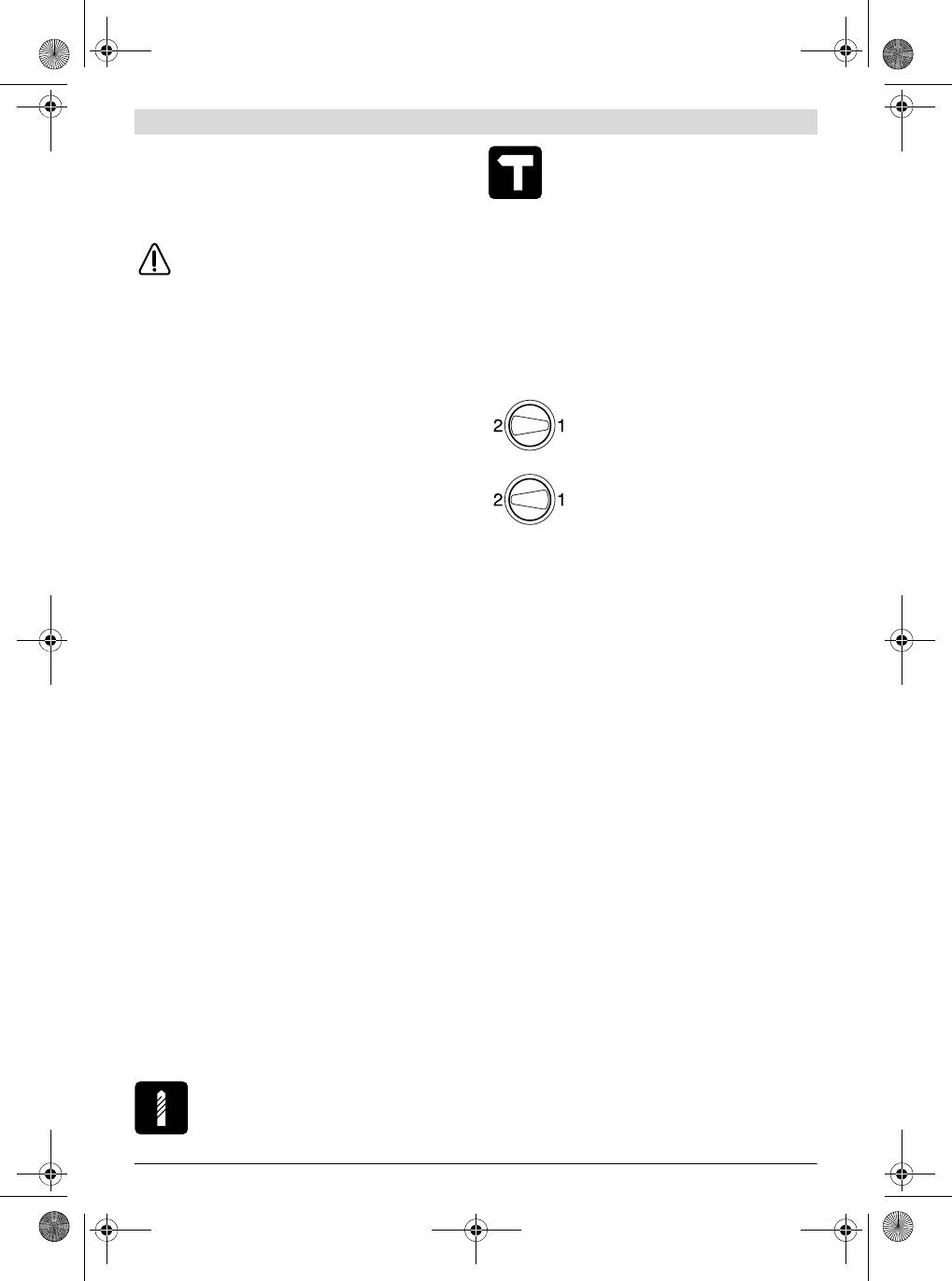
Rechtslauf: Zum Bohren und Eindrehen von Schrauben
schieben Sie den Drehrichtungsumschalter 3 auf der linken
f Schalten Sie das Elektrowerkzeug aus und lösen Sie
Seite nach unten und gleichzeitig auf der rechten Seite nach
das Einsatzwerkzeug, wenn das Elektrowerkzeug blo-
oben.
ckiert. Beim Einschalten mit einem blockierten Bohr-
werkzeug entstehen hohe Reaktionsmomente.
Linkslauf: Zum Lösen bzw. Herausdrehen von Schrauben
und Muttern schieben Sie den Drehrichtungsumschalter 3 auf
Drehzahl/Schlagzahl einstellen
der linken Seite nach oben und gleichzeitig auf der rechten
Sie können die Drehzahl/Schlagzahl des eingeschalteten
Seite nach unten.
Elektrowerkzeugs stufenlos regulieren, je nachdem, wie weit
Sie den Ein-/Ausschalter 6 eindrücken.
Betriebsart einstellen
Bohren und Schrauben
Leichter Druck auf den Ein-/Ausschalter 6 bewirkt eine nied-
rige Drehzahl/Schlagzahl. Mit zunehmendem Druck erhöht
Stellen Sie den Umschalter 2 auf das Symbol
sich die Drehzahl/Schlagzahl.
„Bohren“.
1 619 929 J12 | (27.4.11) Bosch Power Tools
OBJ_BUCH-824-004.book Page 11 Wednesday, April 27, 2011 10:54 AM
English | 11
Drehzahl/Schlagzahl vorwählen
www.powertool-portal.de, das Internetportal für Handwer-
Mit dem Stellrad Drehzahlvorwahl 5 können Sie die benötigte
ker und Heimwerker.
Drehzahl/Schlagzahl auch während des Betriebes vorwählen.
www.ewbc.de, der Informations-Pool für Handwerk und Aus-
bildung.
Die erforderliche Drehzahl/Schlagzahl ist vom Werkstoff und
den Arbeitsbedingungen abhängig und kann durch prakti-
Deutschland
schen Versuch ermittelt werden.
Robert Bosch GmbH
Servicezentrum Elektrowerkzeuge
Arbeitshinweise
Zur Luhne 2
f Ziehen Sie vor allen Arbeiten am Elektrowerkzeug den
37589 Kalefeld – Willershausen
Netzstecker aus der Steckdose.
Tel. Kundendienst: +49 (1805) 70 74 10*
f Setzen Sie das Elektrowerkzeug nur ausgeschaltet auf
Fax: +49 (1805) 70 74 11*
die Mutter/Schraube auf. Sich drehende Einsatzwerk-
(*Festnetzpreis 14 ct/min, höchstens 42 ct/min aus Mobil-
zeuge können abrutschen.
funknetzen)
E-Mail: Servicezentrum.Elektrowerkzeuge@de.bosch.com
Tipps
Tel. Kundenberatung: +49 (1803) 33 57 99
Nach längerem Arbeiten mit kleiner Drehzahl sollten Sie das
(Festnetzpreis 9 ct/min, höchstens 42 ct/min aus Mobilfunk-
Elektrowerkzeug zur Abkühlung ca. 3 Minuten lang bei maxi-
netzen)
maler Drehzahl im Leerlauf drehen lassen.
Fax: +49 (711) 7 58 19 30
Um Fliesen zu bohren, stellen Sie den Umschalter 2 auf das
E-Mail: kundenberatung.ew@de.bosch.com
Symbol „Bohren“. Nach dem Durchbohren der Fliese stellen
Österreich
Sie den Umschalter auf das Symbol „Schlagbohren“ um und
arbeiten mit Schlag.
Tel.: +43 (01) 7 97 22 20 10
Fax: +43 (01) 7 97 22 20 11
Bei Arbeiten in Beton, Gestein und Mauerwerk verwenden Sie
E-Mail: service.elektrowerkzeuge@at.bosch.com
Hartmetallbohrer.
Verwenden Sie beim Bohren in Metall nur einwandfreie, ge-
Schweiz
schärfte HSS-Bohrer (HSS=Hochleistungs-Schnellschnitt-
Tel.: +41 (044) 8 47 15 11
stahl). Entsprechende Qualität garantiert das Bosch-Zube-
Fax: +41 (044) 8 47 15 51
hör-Programm.
Luxemburg
Mit dem Bohrerschärfgerät (Zubehör) können Sie Spiralboh-
Tel.: +32 (070) 22 55 65
rer mit einem Durchmesser von 2,5–10 mm mühelos schär-
Fax: +32 (070) 22 55 75
fen.
E-Mail: outillage.gereedschap@be.bosch.com
Entsorgung
Wartung und Service
Elektrowerkzeuge, Zubehör und Verpackungen sollen einer
Wartung und Reinigung
umweltgerechten Wiederverwertung zugeführt werden.
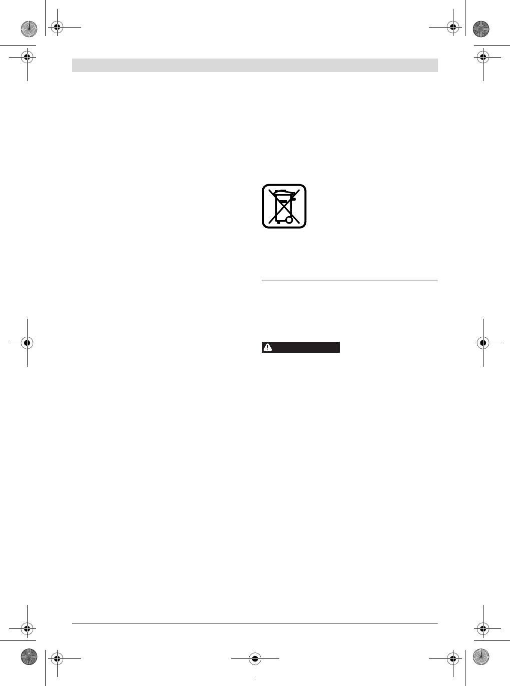
Werfen Sie Elektrowerkzeuge nicht in den Hausmüll!
f Ziehen Sie vor allen Arbeiten am Elektrowerkzeug den
Netzstecker aus der Steckdose.
Nur für EU-Länder:
f Halten Sie das Elektrowerkzeug und die Lüftungsschlit-
Gemäß der Europäischen Richtlinie
ze sauber, um gut und sicher zu arbeiten.
2002/96/EG über Elektro- und Elektronik-
Altgeräte und ihrer Umsetzung in nationales
Sollte das Elektrowerkzeug trotz sorgfältiger Herstellungs-
Recht müssen nicht mehr gebrauchsfähige
und Prüfverfahren einmal ausfallen, ist die Reparatur von ei-
Elektrowerkzeuge getrennt gesammelt und
ner autorisierten Kundendienststelle für Bosch-Elektrowerk-
einer umweltgerechten Wiederverwertung
zeuge ausführen zu lassen.
zugeführt werden.
Geben Sie bei allen Rückfragen und Ersatzteilbestellungen
Änderungen vorbehalten.
bitte unbedingt die 10-stellige Sachnummer laut Typenschild
des Elektrowerkzeuges an.
Kundendienst und Kundenberatung
Der Kundendienst beantwortet Ihre Fragen zu Reparatur und
English
Wartung Ihres Produkts sowie zu Ersatzteilen. Explosions-
zeichnungen und Informationen zu Ersatzteilen finden Sie
Safety Notes
auch unter:
www.bosch-pt.com
General Power Tool Safety Warnings
Das Bosch-Kundenberater-Team hilft Ihnen gerne bei Fragen
Read all safety warnings and all in-
zu Kauf, Anwendung und Einstellung von Produkten und Zu-
WARNING
structions. Failure to follow the warnings
behören.
and instructions may result in electric shock, fire and/or seri-
ous injury.
Bosch Power Tools 1 619 929 J12 | (27.4.11)

OBJ_BUCH-824-004.book Page 12 Wednesday, April 27, 2011 10:54 AM
12 | English
Save all warnings and instructions for future reference.
f Do not overreach. Keep proper footing and balance at
The term “power tool” in the warnings refers to your mains-
all times. This enables better control of the power tool in
operated (corded) power tool or battery-operated (cordless)
unexpected situations.
power tool.
f Dress properly. Do not wear loose clothing or jewel-
lery. Keep your hair, clothing and gloves away from
Work area safety
moving parts. Loose clothes, jewellery or long hair can be
f Keep work area clean and well lit. Cluttered or dark areas
caught in moving parts.
invite accidents.
f If devices are provided for the connection of dust ex-
f Do not operate power tools in explosive atmospheres,
traction and collection facilities, ensure these are con-
such as in the presence of flammable liquids, gases or
nected and properly used. Use of dust collection can re-
dust. Power tools create sparks which may ignite the dust
duce dust-related hazards.
or fumes.
Power tool use and care
f Keep children and bystanders away while operating a
power tool. Distractions can cause you to lose control.
f Do not force the power tool. Use the correct power tool
for your application. The correct power tool will do the
Electrical safety
job better and safer at the rate for which it was designed.
f Power tool plugs must match the outlet. Never modify
f Do not use the power tool if the switch does not turn it
the plug in any way. Do not use any adapter plugs with
on and off.
Any power tool that cannot be controlled with
earthed (grounded) power tools. Unmodified plugs and
the switch is dangerous and must be repaired.
matching outlets will reduce risk of electric shock.
f Disconnect the plug from the power source and/or the
f Avoid body contact with earthed or grounded surfaces,
battery pack from the power tool before making any
such as pipes, radiators, ranges and refrigerators.
adjustments, changing accessories, or storing power
There is an increased risk of electric shock if your body is
tools. Such preventive safety measures reduce the risk of
earthed or grounded.
starting the power tool accidentally.
f Do not expose power tools to rain or wet conditions.
f Store idle power tools out of the reach of children and
Water entering a power tool will increase the risk of electric
do not allow persons unfamiliar with the power tool or
shock.
these instructions to operate the power tool. Power
f Do not abuse the cord. Never use the cord for carrying,
tools are dangerous in the hands of untrained users.
pulling or unplugging the power tool. Keep cord away
f Maintain power tools. Check for misalignment or bind-
from heat, oil, sharp edges and moving parts. Damaged
ing of moving parts, breakage of parts and any other
or entangled cords increase the risk of electric shock.
condition that may affect the power tool’s operation. If
f When operating a power tool outdoors, use an exten-
damaged, have the power tool repaired before use.
sion cord suitable for outdoor use. Use of a cord suitable
Many accidents are caused by poorly maintained power
for outdoor use reduces the risk of electric shock.
tools.
f If operating a power tool in a damp location is unavoid-
f Keep cutting tools sharp and clean. Properly maintained
able, use a residual current device (RCD) protected
cutting tools with sharp cutting edges are less likely to bind
supply. Use of an RCD reduces the risk of electric shock.
and are easier to control.
Personal safety
f Use the power tool, accessories and tool bits etc. in ac-
f Stay alert, watch what you are doing and use common
cordance with these instructions, taking into account
sense when operating a power tool. Do not use a power
the working conditions and the work to be performed.
tool while you are tired or under the influence of drugs,
Use of the power tool for operations different from those
alcohol or medication. A moment of inattention while op-
intended could result in a hazardous situation.
erating power tools may result in serious personal injury.
Service
f Use personal protective equipment. Always wear eye
f Have your power tool serviced by a qualified repair per-
protection. Protective equipment such as dust mask,
son using only identical replacement parts. This will en-
non-skid safety shoes, hard hat, or hearing protection
sure that the safety of the power tool is maintained.
used for appropriate conditions will reduce personal inju-
ries.
Safety Warnings for Drills
f Prevent unintentional starting. Ensure the switch is in
f Wear ear protectors when impact drilling. Exposure to
the off-position before connecting to power source
noise can cause hearing loss.
and/or battery pack, picking up or carrying the tool.
f Use auxiliary handle(s), if supplied with the tool. Loss
Carrying power tools with your finger on the switch or en-
of control can cause personal injury.
ergising power tools that have the switch on invites acci-
f Hold the tool by the insulated gripping surfaces when
dents.
performing operations where the application tool or
f Remove any adjusting key or wrench before turning
the screw could contact hidden wiring or its own power
the power tool on. A wrench or a key left attached to a ro-
cord. Contact with a “live” wire will also make exposed
tating part of the power tool may result in personal injury.
metal parts of the power tool “live” and shock the operator.
1 619 929 J12 | (27.4.11) Bosch Power Tools
OBJ_BUCH-824-004.book Page 13 Wednesday, April 27, 2011 10:54 AM
English | 13
f Use appropriate detectors to determine if utility lines
While reading the operating instructions, unfold the graphics
are hidden in the work area or call the local utility com-
page for the machine and leave it open.
pany for assistance. Contact with electric lines can lead
to fire and electric shock. Damaging a gas line can lead to
Intended Use
explosion. Penetrating a water line causes property dam-
The machine is intended for impact drilling in brick, concrete
age.
and stone as well as for drilling in wood, metal and plastic. Ma-
f When working with the machine, always hold it firmly
chines with electronic control and right/left rotation are also
with both hands and provide for a secure stance. The
suitable for screwdriving and thread-cutting.
power tool is guided more secure with both hands.
Product Features
f Secure the workpiece. A workpiece clamped with clamp-
ing devices or in a vice is held more secure than by hand.
The numbering of the product features refers to the illustra-
tion of the machine on the graphics page.
f Always wait until the machine has come to a complete
stop before placing it down. The tool insert can jam and
1 Keyless chuck
lead to loss of control over the power tool.
2 “Drilling/Impact Drilling” selector switch
Products sold in GB only: Your product is fitted with a
3 Rotational direction switch
BS 1363/A approved electric plug with internal fuse (ASTA
4 Lock-on button for On/Off switch
approved to BS 1362).
5 Thumbwheel for speed preselection
If the plug is not suitable for your socket outlets, it should be
6 On/Off switch
cut off and an appropriate plug fitted in its place by an author-
7 Gear selector
ised customer service agent. The replacement plug should
8 Auxiliary handle (insulated gripping surface)*
have the same fuse rating as the original plug.
The severed plug must be disposed of to avoid a possible
9 Depth stop*
shock hazard and should never be inserted into a mains sock-
10 Handle (insulated gripping surface)
et elsewhere.
11 Front sleeve*
Products sold in AUS and NZ only: Use a residual current de-
12 Rear sleeve*
vice (RCD) with a rated residual current of 30 mA or less.
13 Chuck key*
14 Key type drill chuck*
Product Description and
15 Screwdriver bit*
Specifications
16 Universal bit holder*
Read all safety warnings and all instruc-
17 Allen key *
tions. Failure to follow the warnings and in-
*Accessories shown or described are not part of the standard de-
livery scope of the product. A complete overview of accessories
structions may result in electric shock, fire
can be found in our accessories program.
and/or serious injury.
Technical Data
Impact Drill GSB 19-2 RE
GSB 19-2 RE
GSB 780
Professional
Professional
Professional
Article number 3 601 A7B 5.. 3 601 A7B 6.. 3 601 A7B 1..
Rated power input
W850850 780
Output power
W430430 390
No-load speed
-1
–1st gear
min
0–1000
0–1000
0–1000
-1
– 2nd gear
min
0–3000
0–3000
0–3000
Rated speed
-1
–1st gear
min
800
800
850
-1
– 2nd gear
min
2060
2060
2170
-1
Impact frequency at no-load
min
51000 51000 51000
Rated torque (1st/2nd gear)
Nm 5.2/2.0 5.2/2.0 4.1/1.6
Speed preselection
z zz
Right/left rotation
z zz
Key type drill chuck
– z –
The values given are valid for a nominal voltage [U] of 230 V. For different voltages and models for specific countries, these values can vary.
Please observe the article number on the type plate of your machine. The trade names of the individual machines may vary.
Bosch Power Tools 1 619 929 J12 | (27.4.11)
OBJ_BUCH-824-004.book Page 14 Wednesday, April 27, 2011 10:54 AM
14 | English
Impact Drill GSB 19-2 RE
GSB 19-2 RE
GSB 780
Professional
Professional
Professional
Keyless drill chuck
z – z
Fully automatic spindle locking (Auto-lock)
z ––
Spindle collar dia.
mm 43 43 43
Maximum drilling diameter (1st/2nd gear)
– Concrete
mm
18/13
18/13
18/13
– Brickwork
mm
20/15
20/15
20/15
–Steel
mm
13/8
13/8
13/8
– Wood
mm
40/25
40/25
40/25
Chuck clamping range
mm 1.5 –13 1.5 – 13 1.5 – 13
Weight according to EPTA-Procedure 01/2003
kg 2.6 2.6 2.6
Protection class
/II /II /II
The values given are valid for a nominal voltage [U] of 230 V. For different voltages and models for specific countries, these values can vary.
Please observe the article number on the type plate of your machine. The trade names of the individual machines may vary.
Noise/Vibration Information
Technical file at:
Robert Bosch GmbH, PT/ESC,
Measured sound values determined according to EN 60745.
D-70745 Leinfelden-Echterdingen
Typically the A-weighted noise levels of the product are:
Dr. Egbert Schneider
Dr. Eckerhard Strötgen
Sound pressure level 95 dB(A); Sound power level
Senior Vice President
Head of Product
106 dB(A). Uncertainty K =3 dB.
Engineering
Certification
Wear hearing protection!
Vibration total values a
h
(triax vector sum) and uncertainty K
determined according to EN 60745:
2
2
Drilling into metal: a
h
=3.0m/s
, K=1.5 m/s
,
2
2
Impact drilling into concrete: a
h
=15m/s
, K=2.0 m/s
,
Robert Bosch GmbH, Power Tools Division
2
2
Screwdriving without impact: a
h
<2.5m/s
, K=1.5 m/s
,
D-70745 Leinfelden-Echterdingen
2
2
Tapping: a
<2.5m/s
, K=1.5 m/s
.
18.02.2010
h
The vibration emission level given in this information sheet
has been measured in accordance with a standardised test
Assembly
given in EN 60745 and may be used to compare one tool with
f Before any work on the machine itself, pull the mains
another. It may be used for a preliminary assessment of expo-
plug.
sure.
The declared vibration emission level represents the main ap-
Auxiliary Handle (see figure A)
plications of the tool. However if the tool is used for different
f Operate your machine only with the auxiliary handle 8.
applications, with different accessories or poorly maintained,
The auxiliary handle 8 can be set in 12 positions to achieve a
the vibration emission may differ. This may significantly in-
safe and low-fatigue working stance.
crease the exposure level over the total working period.
An estimation of the level of exposure to vibration should also
Turn the bottom part of the auxiliary handle 8 in rotation di-
take into account the times when the tool is switched off or
rection n and push the auxiliary handle 8 forward until you
when it is running but not actually doing the job. This may sig-
can pivot it to the desired position. Then pull the auxiliary han-
nificantly reduce the exposure level over the total working pe-
dle 8 back again and tighten it by turning the bottom part of
riod.
the auxiliary handle in rotation direction o.
Identify additional safety measures to protect the operator
Adjusting the Drilling Depth (see figure A)
from the effects of vibration such as: maintain the tool and the
The required drilling depth X can be set with the depth stop 9.
accessories, keep the hands warm, organisation of work pat-
terns.
Turn the bottom part of the auxiliary handle 8 in anticlockwise
direction and insert the depth stop 9.
Declaration of Conformity
Pull out the depth stop until the distance between the tip of
We declare under our sole responsibility that the product de-
the drill bit and the tip of the depth stop correspond with the
scribed under “Technical Data” is in conformity with the fol-
desired drilling depth X.
lowing standards or standardization documents: EN 60745
Afterwards, tighten the bottom part of the auxiliary handle 8
according to the provisions of the directives 2004/108/EC,
again by turning in clockwise direction.
2006/42/EC.
The knurled surface of the depth stop 9 must face upward.
1 619 929 J12 | (27.4.11) Bosch Power Tools
OBJ_BUCH-824-004.book Page 15 Wednesday, April 27, 2011 10:54 AM
English | 15
Changing the Tool
For machines with key chuck, disassembly is carried out anal-
ogous as described above.
f Wear protective gloves when changing the tool. The
drill chuck can become very hot during longer work peri-
For machines with keyless chuck, an open-end spanner (size
ods.
19 mm) can be applied to the drill chuck instead of an Allen
key.
Keyless Chuck (GSB 19-2 RE) (see figure B)
The drill spindle is locked when the On/Off switch 6 is not
Mounting the Drill Chuck (see figure G)
pressed. This makes quick, convenient and easy changing of
The keyless chuck/key type drill chuck is mounted in reverse
the tool in the drill chuck possible.
order.
Open the keyless chuck 1 by turning in rotation direction n,
f Remove the steel pin from the drill hole on the spindle
until the tool can be inserted. Insert the tool.
neck after mounting is completed.
Firmly tighten the collar of the keyless chuck 1 by hand in ro-
The drill chuck must be tightened with a tighten-
tation direction o until the locking action (“click”) is no longer
ing torque of approx. 50–55 Nm.
heard. This automatically locks the chuck.
The locking is released again to remove the tool when the col-
Dust/Chip Extraction
lar is turned in the opposite direction.
f Dusts from materials such as lead-containing coatings,
Keyless Chuck (GSB 780) (see figure C)
some wood types, minerals and metal can be harmful to
Hold the rear sleeve 12 of the keyless chuck 1 tight and turn
one’s health. Touching or breathing-in the dusts can cause
the front sleeve 11 in rotation direction n, until the tool can
allergic reactions and/or lead to respiratory infections of
be inserted. Insert the tool.
the user or bystanders.
Hold the rear sleeve 12 of the keyless chuck 1 tight and firmly
Certain dusts, such as oak or beech dust, are considered
turn the front sleeve 11 in rotation direction o by hand until
as carcinogenic, especially in connection with wood-treat-
the locking action is no longer heard. This automatically locks
ment additives (chromate, wood preservative). Materials
the drill chuck.
containing asbestos may only be worked by specialists.
The locking is released again to remove the tool when the
– Provide for good ventilation of the working place.
front sleeve 11 is turned in the opposite direction.
– It is recommended to wear a P2 filter-class respirator.
Observe the relevant regulations in your country for the
Key Type Drill Chuck (see figure D)
materials to be worked.
Open the key type drill chuck 14 by turning until the tool can
f Prevent dust accumulation at the workplace. Dusts can
be inserted. Insert the tool.
easily ignite.
Insert the chuck key 13 into the corresponding holes of the
key type drill chuck 14 and clamp the tool uniformly.
Operation
Screwdriver Tools (see figure E)
When working with screwdriver bits 15, a universal bit holder
Starting Operation
16 should always be used. Use only screwdriver bits that fit
f Observe correct mains voltage! The voltage of the pow-
the screw head.
er source must agree with the voltage specified on the
For driving screws, always position the “Drilling/Impact Drill-
nameplate of the machine. Power tools marked with
ing” selector switch 2 to the “Drilling” symbol.
230 V can also be operated with 220 V.
Replacing the Drill Chuck
Reversing the Rotational Direction (see figure H)
f Actuate the rotational direction switch 3 only when the
f Before any work on the machine itself, pull the mains
machine is at a standstill.
plug.
The rotational direction switch 3 is used to reverse the rota-
Removing the Drill Chuck (see figure F)
tional direction of the machine. However, this is not possible
Disassemble the auxiliary handle and set the gear selector 7
with the On/Off switch 6 actuated.
to the centre position between the 1st and 2nd gear.
Right rotation: For drilling and driving in screws, push the ro-
Insert a steel pin with a diameter of Ø 4 mm and approx.
tational direction switch 3 downward on the left side and at
50 mm of length into the drill hole on the spindle neck in order
the same time upward on the right side.
to lock the drill spindle.
Left rotation: For loosening and unscrewing screws and
Clamp the short end of an Allen key 17 into the keyless chuck
nuts, push the rotational direction switch 3 upward on the left
1.
side and at the same time downward on the right side.
Place the machine on a stable surface (e. g. a workbench).
Setting the Operating Mode
Hold the machine firmly and loosen the keyless chuck 1 by
Drilling and Screwdriving
turning the Allen key 17 in rotation direction n. Loosen a
tight-seated keyless chuck by giving the long end of the Allen
Set the selector switch 2 to the “Drilling”
key 17 a light blow. Remove the Allen key from the keyless
symbol.
chuck and completely unscrew the keyless chuck.
Bosch Power Tools 1 619 929 J12 | (27.4.11)
OBJ_BUCH-824-004.book Page 16 Wednesday, April 27, 2011 10:54 AM
16 | English
Impact Drilling
The required speed/impact frequency depends on the mate-
Set the selector switch 2 to the “Impact drilling”
rial and the working conditions, and can be determined
symbol.
through practical testing.
Working Advice
The selector switch 2 engages noticeably and can also be ac-
f Before any work on the machine itself, pull the mains
tuated with the machine running.
plug.
Gear Selection, Mechanical
f Apply the power tool to the screw/nut only when it is
f The gear selector 7 can be actuated on machines run-
switched off. Rotating tool inserts can slip off.
ning at low speed. However, this should not be done
when the machine is stopped, at full load or running at
Tips
maximum speed.
After longer periods of working at low speed, allow the ma-
chine to cool down by running it for approx. 3 minutes at max-
Two speed ranges can be preselected with the gear selector
imum speed with no load.
7.
For drilling in tiles, set the selector switch 2 to the “Drilling”
Gear I:
symbol. Do not switch over to the symbol “Impact Drilling” or
Low speed range; for working with large drill-
work with impact until after drilling through the tile.
ing diameter or for driving in screws.
Use carbide tipped drill bits when working in concrete, ma-
sonry and brick wall.
Gear II:
For drilling in metal, use only perfectly sharpened HSS drill
High speed range; for working with small
bits (HSS=high-speed steel). The appropriate quality is guar-
drilling diameter.
anteed by the Bosch accessories program.
Twist drills from 2.5–10 mm can easily be sharpened with
If the gear selector 7 cannot be fully engaged, lightly rotate
the drill bit sharpener (see accessories).
the drive spindle with the drill bit by twisting the drill chuck.
Switching On and Off
Maintenance and Service
To start the machine, press the On/Off switch 6 and keep it
pressed.
Maintenance and Cleaning
To lock the pressed On/Off switch 6, press the lock-on button
f Before any work on the machine itself, pull the mains
4.
plug.
To switch off the machine, release the On/Off switch 6 or
f For safe and proper working, always keep the machine
when it is locked with the lock-on button 4, briefly press the
and ventilation slots clean.
On/Off switch 6 and then release it.
If the machine should fail despite the care taken in manufac-
Safety Clutch
turing and testing procedures, repair should be carried out by
To limit high reaction torque, the power tool is equipped with
an after-sales service centre for Bosch power tools.
a safety clutch (Anti-Rotation).
In all correspondence and spare parts order, please always in-
f If the tool insert becomes caught or jammed, the drive
clude the 10-digit article number given on the type plate of
to the drill spindle is interrupted. Because of the forces
the machine.
that occur, always hold the power tool firmly with both
hands and provide for a secure stance.
After-sales Service and Customer Assistance
f If the power tool jams, switch the machine off and loos-
Our after-sales service responds to your questions concern-
en the tool insert. When switching the machine on with
ing maintenance and repair of your product as well as spare
the drilling tool jammed, high reaction torques can oc-
parts. Exploded views and information on spare parts can al-
cur.
so be found under:
www.bosch-pt.com
Adjusting the Speed/Impact Frequency
Our customer service representatives can answer your ques-
The speed/impact rate of the switched on power tool can be
tions concerning possible applications and adjustment of
variably adjusted, depending on how far the On/Off switch 6
products and accessories.
is pressed.
Light pressure on the On/Off switch 6 results in low speed/im-
pact rate. Further pressure on the switch increases the
speed/impact rate.
Preselecting the Speed/Impact Frequency
With the thumbwheel for speed preselection 5, the required
speed/impact frequency can be preselected even during op-
eration.
1 619 929 J12 | (27.4.11) Bosch Power Tools
OBJ_BUCH-824-004.book Page 17 Wednesday, April 27, 2011 10:54 AM
Français | 17
Great Britain
Bosch Headquarters
Robert Bosch Ltd. (B.S.C.)
Midrand, Gauteng
P.O. Box 98
Tel.: +27 (011) 6 51 96 00
Broadwater Park
Fax: +27 (011) 6 51 98 80
North Orbital Road
E-Mail: rbsa-hq.pts@za.bosch.com
Denham
Disposal
Uxbridge
UB 9 5HJ
The machine, accessories and packaging should be sorted for
Tel. Service: +44 (0844) 736 0109
environmental-friendly recycling.
Fax: +44 (0844) 736 0146
Do not dispose of power tools into household waste!
E-Mail: boschservicecentre@bosch.com
Only for EC countries:
Ireland
According the European Guideline
Origo Ltd.
2002/96/EC for Waste Electrical and Elec-
Unit 23 Magna Drive
tronic Equipment and its implementation
Magna Business Park
into national right, power tools that are no
City West
longer usable must be collected separately
Dublin 24
and disposed of in an environmentally cor-
Tel. Service: +353 (01) 4 66 67 00
rect manner.
Fax: +353 (01) 4 66 68 88
Subject to change without notice.
Australia, New Zealand and Pacific Islands
Robert Bosch Australia Pty. Ltd.
Power Tools
Locked Bag 66
Français
Clayton South VIC 3169
Customer Contact Center
Avertissements de sécurité
Inside Australia:
Phone: +61 (01300) 307 044
Avertissements de sécurité généraux pour l’outil
Fax: +61 (01300) 307 045
Inside New Zealand:
Lire tous les avertissements
AVERTISSEMENT
Phone: +64 (0800) 543 353
de sécurité et toutes les ins-
Fax: +64 (0800) 428 570
tructions. Ne pas suivre les avertissements et instructions
Outside AU and NZ:
peut donner lieu à un choc électrique, un incendie et/ou une
Phone: +61 (03) 9541 5555
blessure sérieuse.
www.bosch.com.au
Conserver tous les avertissements et toutes les instruc-
tions pour pouvoir s’y reporter ultérieurement.
Republic of South Africa
Customer service
Le terme « outil » dans les avertissements fait référence à vo-
Hotline: +27 (011) 6 51 96 00
tre outil électrique alimenté par le secteur (avec cordon d’ali-
mentation) ou votre outil fonctionnant sur batterie (sans cor-
Gauteng – BSC Service Centre
don d’alimentation).
35 Roper Street, New Centre
Johannesburg
Sécurité de la zone de travail
Tel.: +27 (011) 4 93 93 75
f Conserver la zone de travail propre et bien éclairée. Les
Fax: +27 (011) 4 93 01 26
zones en désordre ou sombres sont propices aux acci-
E-Mail: bsctools@icon.co.za
dents.
KZN – BSC Service Centre
f Ne pas faire fonctionner les outils électriques en at-
Unit E, Almar Centre
mosphère explosive, par exemple en présence de liqui-
143 Crompton Street
des inflammables, de gaz ou de poussières. Les outils
Pinetown
électriques produisent des étincelles qui peuvent enflam-
Tel.: +27 (031) 7 01 21 20
mer les poussières ou les fumées.
Fax: +27 (031) 7 01 24 46
f Maintenir les enfants et les personnes présentes à
E-Mail: bsc.dur@za.bosch.com
l’écart pendant l’utilisation de l’outil. Les distractions
Western Cape – BSC Service Centre
peuvent vous faire perdre le contrôle de l’outil.
Democracy Way, Prosperity Park
Sécurité électrique
Milnerton
f Il faut que les fiches de l’outil électrique soient adap-
Tel.: +27 (021) 5 51 25 77
tées au socle. Ne jamais modifier la fiche de quelque fa-
Fax: +27 (021) 5 51 32 23
çon que ce soit. Ne pas utiliser d’adaptateurs avec des
E-Mail: bsc@zsd.co.za
outils à branchement de terre. Des fiches non modifiées
Bosch Power Tools 1 619 929 J12 | (27.4.11)
OBJ_BUCH-824-004.book Page 18 Wednesday, April 27, 2011 10:54 AM
18 | Français
et des socles adaptés réduiront le risque de choc électri-
ment utilisés. Utiliser des collecteurs de poussière peut
que.
réduire les risques dus aux poussières.
f Eviter tout contact du corps avec des surfaces reliées à
Utilisation et entretien de l’outil
la terre telles que les tuyaux, les radiateurs, les cuisi-
f Ne pas forcer l’outil. Utiliser l’outil adapté à votre appli-
nières et les réfrigérateurs. Il existe un risque accru de
cation. L’outil adapté réalisera mieux le travail et de maniè-
choc électrique si votre corps est relié à la terre.
re plus sûre au régime pour lequel il a été construit.
f Ne pas exposer les outils à la pluie ou à des conditions
f Ne pas utiliser l’outil si l’interrupteur ne permet pas de
humides. La pénétration d’eau à l’intérieur d’un outil aug-
passer de l’état de marche à arrêt et vice versa. Tout
mentera le risque de choc électrique.
outil qui ne peut pas être commandé par l’interrupteur est
f Ne pas maltraiter le cordon. Ne jamais utiliser le cordon
dangereux et il faut le faire réparer.
pour porter, tirer ou débrancher l’outil. Maintenir le
f Débrancher la fiche de la source d’alimentation en cou-
cordon à l’écart de la chaleur, du lubrifiant, des arêtes
rant et/ou le bloc de batteries de l’outil avant tout ré-
ou des parties en mouvement. Les cordons endommagés
glage, changement d’accessoires ou avant de ranger
ou emmêlés augmentent le risque de choc électrique.
l’outil. De telles mesures de sécurité préventives rédui-
f Lorsqu’on utilise un outil à l’extérieur, utiliser un pro-
sent le risque de démarrage accidentel de l’outil.
longateur adapté à l’utilisation extérieure. L’utilisation
f Conserver les outils à l’arrêt hors de la portée des en-
d’un cordon adapté à l’utilisation extérieure réduit le risque
fants et ne pas permettre à des personnes ne connais-
de choc électrique.
sant pas l’outil ou les présentes instructions de le faire
f Si l’usage d’un outil dans un emplacement humide est
fonctionner. Les outils sont dangereux entre les mains
inévitable, utiliser une alimentation protégée par un
d’utilisateurs novices.
dispositif à courant différentiel résiduel (RCD). L’usage
f Observer la maintenance de l’outil. Vérifier qu’il n’y a
d’un RCD réduit le risque de choc électrique.
pas de mauvais alignement ou de blocage des parties
Sécurité des personnes
mobiles, des pièces cassées ou toute autre condition
f Rester vigilant, regarder ce que vous êtes en train de
pouvant affecter le fonctionnement de l’outil. En cas de
faire et faire preuve de bon sens dans l’utilisation de
dommages, faire réparer l’outil avant de l’utiliser. De
l’outil. Ne pas utiliser un outil lorsque vous êtes fatigué
nombreux accidents sont dus à des outils mal entretenus.
ou sous l’emprise de drogues, d’alcool ou de médica-
f Garder affûtés et propres les outils permettant de cou-
ments. Un moment d’inattention en cours d’utilisation
per. Des outils destinés à couper correctement entretenus
d’un outil peut entraîner des blessures graves des person-
avec des pièces coupantes tranchantes sont moins sus-
nes.
ceptibles de bloquer et sont plus faciles à contrôler.
f Utiliser un équipement de sécurité. Toujours porter
f Utiliser l’outil, les accessoires et les lames etc., confor-
une protection pour les yeux. Les équipements de sécu-
mément à ces instructions, en tenant compte des con-
rité tels que les masques contre les poussières, les chaus-
ditions de travail et du travail à réaliser. L’utilisation de
sures de sécurité antidérapantes, les casques ou les pro-
l’outil pour des opérations différentes de celles prévues
tections acoustiques utilisés pour les conditions
pourrait donner lieu à des situations dangereuses.
appropriées réduiront les blessures des personnes.
Maintenance et entretien
f Eviter tout démarrage intempestif. S’assurer que l’in-
f Faire entretenir l’outil par un réparateur qualifié utili-
terrupteur est en position arrêt avant de brancher
sant uniquement des pièces de rechange identiques.
l’outil au secteur et/ou au bloc de batteries, de le ra-
Cela assurera que la sécurité de l’outil est maintenue.
masser ou de le porter. Porter les outils en ayant le doigt
sur l’interrupteur ou brancher des outils dont l’interrupteur
Avertissements de sécurité pour la perceuse
est en position marche est source d’accidents.
f Porter des protecteurs d’oreilles lors du perçage avec
f Retirer toute clé de réglage avant de mettre l’outil en
des perceuses à percussion. L’exposition aux bruits peut
marche. Une clé laissée fixée sur une partie tournante de
provoquer une perte de l’audition.
l’outil peut donner lieu à des blessures de personnes.
f Utiliser la(les) poignée(s) auxiliaire(s) fournie(s) avec
f Ne pas se précipiter. Garder une position et un équili-
l’outil. La perte de contrôle peut provoquer des blessures.
bre adaptés à tout moment. Cela permet un meilleur con-
f Tenir l’outil par les surfaces de préhension isolantes,
trôle de l’outil dans des situations inattendues.
pendant les opérations au cours desquelles l’accessoi-
f S’habiller de manière adaptée. Ne pas porter de vête-
re coupant ou la vis peut être en contact avec des con-
ments amples ou de bijoux. Garder les cheveux, les vê-
ducteurs cachés ou avec son propre câble. Le contact de
tements et les gants à distance des parties en mouve-
l’accessoire coupant avec un fil sous tension peut égale-
ment. Des vêtements amples, des bijoux ou les cheveux
ment mettre sous tension les parties métalliques visibles
longs peuvent être pris dans des parties en mouvement.
de l’outil électrique et entraîner l’électrocution de l’opéra-
f Si des dispositifs sont fournis pour le raccordement
teur.
d’équipements pour l’extraction et la récupération des
f Utiliser des détecteurs appropriés afin de déceler des
poussières, s’assurer qu’ils sont connectés et correcte-
conduites cachées ou consulter les entreprises d’ap-
1 619 929 J12 | (27.4.11) Bosch Power Tools
OBJ_BUCH-824-004.book Page 19 Wednesday, April 27, 2011 10:54 AM
Français | 19
provisionnement locales. Un contact avec des conduites
Utilisation conforme
d’électricité peut provoquer un incendie ou un choc élec-
L’appareil est conçu pour le perçage à percussion dans la bri-
trique. Un endommagement d’une conduite de gaz peut
que, le béton et dans la pierre naturelle ainsi que pour le per-
provoquer une explosion. La perforation d’une conduite
çage dans le bois, le métal, la céramique et les matières plas-
d’eau provoque des dégâts matériels.
tiques. Les appareils avec réglage électronique et rotation
f Toujours bien tenir l’outil électroportatif des deux
droite/gauche sont également appropriés pour le vissage et le
mains et veiller à toujours garder une position de tra-
filetage.
vail stable. Avec les deux mains, l’outil électroportatif est
guidé de manière plus sûre.
Eléments de l’appareil
f Bloquer la pièce à travailler. Une pièce à travailler serrée
La numérotation des éléments de l’appareil se réfère à la re-
par des dispositifs de serrage appropriés ou dans un étau
présentation de l’outil électroportatif sur la page graphique.
est fixée de manière plus sûre que tenue dans les mains.
1 Mandrin automatique
f Avant de déposer l’outil électroportatif, attendre que
2 Commutateur « Perçage/Perçage à percussion »
celui-ci soit complètement à l’arrêt. L’outil risque de se
3 Commutateur du sens de rotation
coincer, ce qui entraînerait une perte de contrôle de l’outil
4 Bouton de blocage de l’interrupteur Marche/Arrêt
électroportatif.
5 Molette de présélection de la vitesse
6 Interrupteur Marche/Arrêt
7 Commutateur de vitesse
Description et performances du
8 Poignée supplémentaire (surface de préhension
produit
isolante)*
Il est impératif de lire toutes les consignes
9 Butée de profondeur*
de sécurité et toutes les instructions. Le
10 Poignée (surface de préhension isolante)
non-respect des avertissements et instruc-
11 Douille avant*
tions indiqués ci-après peut conduire à une
12 Douille arrière*
électrocution, un incendie et/ou de graves
13 Clé de mandrin*
blessures.
14 Mandrin à couronne dentée*
Dépliez le volet sur lequel l’appareil est représenté de manière
15 Embout de réglage*
graphique. Laissez le volet déplié pendant la lecture de la pré-
16 Porte-embout universel*
sente notice d’utilisation.
17 Clé mâle coudée pour vis à six pans creux *
*Les accessoires décrits ou illustrés ne sont pas tous compris dans
la fourniture. Vous trouverez les accessoires complets dans notre
programme d’accessoires.
Caractéristiques techniques
Perceuse à percussion GSB 19-2 RE
GSB 19-2 RE
GSB 780
Professional
Professional
Professional
N° d’article
3 601 A7B 5.. 3 601 A7B 6.. 3 601 A7B 1..
Puissance nominale absorbée
W850850 780
Puissance utile débitée
W430430 390
Vitesse à vide
– 1ère vitesse
tr/min
0–1000
0–1000
0–1000
– 2ème vitesse
tr/min
0–3000
0–3000
0–3000
Vitesse de rotation nominale
– 1ère vitesse
tr/min
800
800
850
– 2ème vitesse
tr/min
2060
2060
2170
Fréquence de frappe à vide
tr/min 51000 51000 51000
Couple nominal (1ère/2ème vitesse)
Nm 5,2/2,0 5,2/2,0 4,1/1,6
Préréglage de la vitesse de rotation
z zz
Rotation droite/gauche
z zz
Mandrin à couronne dentée
– z –
Ces indications sont valables pour une tension nominale de [U] 230 V. Ces indications peuvent varier pour des tensions plus basses ainsi que pour des
versions spécifiques à certains pays.
Respectez impérativement le numéro d’article se trouvant sur la plaque signalétique de l’outil électroportatif. Les désignations commerciales des dif-
férents outils électroportatifs peuvent varier.
Bosch Power Tools 1 619 929 J12 | (27.4.11)
OBJ_BUCH-824-004.book Page 20 Wednesday, April 27, 2011 10:54 AM
20 | Français
Perceuse à percussion GSB 19-2 RE
GSB 19-2 RE
GSB 780
Professional
Professional
Professional
Mandrin automatique
z – z
Blocage automatique de la broche (Auto-Lock)
z ––
Ø collet de broche
mm 43 43 43
Ø perçage max. (1ère/2ème vitesse)
–Béton
mm
18/13
18/13
18/13
– Maçonnerie
mm
20/15
20/15
20/15
– Acier
mm
13/8
13/8
13/8
–Bois
mm
40/25
40/25
40/25
Plage de serrage du mandrin
mm 1,5 –13 1,5 – 13 1,5 – 13
Poids suivant EPTA-Procedure 01/2003
kg 2,6 2,6 2,6
Classe de protection
/II /II /II
Ces indications sont valables pour une tension nominale de [U] 230 V. Ces indications peuvent varier pour des tensions plus basses ainsi que pour des
versions spécifiques à certains pays.
Respectez impérativement le numéro d’article se trouvant sur la plaque signalétique de l’outil électroportatif. Les désignations commerciales des dif-
férents outils électroportatifs peuvent varier.
Niveau sonore et vibrations
Déclaration de conformité
Valeurs de mesure du niveau sonore relevées conformément
Nous déclarons sous notre propre responsabilité que le pro-
à la norme EN 60745.
duit décrit sous « Caractéristiques techniques » est en confor-
Les mesures réelles (A) des niveaux sonores de l’appareil
mité avec les normes ou documents normatifs suivants :
sont : niveau de pression acoustique 95 dB(A) ; niveau d’in-
EN 60745 conformément aux termes des réglementations en
tensité acoustique 106 dB(A). Incertitude K=3 dB.
vigueur 2004/108/CE, 2006/42/CE.
Porter une protection acoustique !
Dossier technique auprès de :
Valeurs totales des vibrations a
(somme vectorielle des trois
Robert Bosch GmbH, PT/ESC,
h
axes directionnels) et incertitude K relevées conformément à
D-70745 Leinfelden-Echterdingen
la norme EN 60745 :
Dr. Egbert Schneider
Dr. Eckerhard Strötgen
2
2
Perçage du métal : a
h
=3,0m/s
, K=1,5 m/s
,
Senior Vice President
Head of Product
2
Perçage à percussion dans le béton : a
h
=15m/s
,
Engineering
Certification
2
K=2,0m/s
,
2
2
Vissage : a
h
<2,5m/s
, K=1,5 m/s
,
2
2
Fileter : a
h
<2,5m/s
, K=1,5 m/s
.
Le niveau d’oscillation indiqué dans ces instructions d’utilisa-
Robert Bosch GmbH, Power Tools Division
tion a été mesuré conformément à la norme EN 60745 et peut
D-70745 Leinfelden-Echterdingen
être utilisé pour une comparaison d’outils électroportatifs. Il
18.02.2010
est également approprié pour une estimation préliminaire de
la charge vibratoire.
Montage
Le niveau d’oscillation correspond aux utilisations principales
de l’outil électroportatif. Si l’outil électrique est cependant
f Avant d’effectuer des travaux sur l’outil électroporta-
utilisé pour d’autres applications, avec d’autres outils de tra-
tif, retirez la fiche de la prise de courant.
vail ou avec un entretien non approprié, le niveau d’oscillation
peut être différent. Ceci peut augmenter considérablement la
Poignée supplémentaire (voir figure A)
charge vibratoire pendant toute la durée de travail.
f N’utilisez l’outil électroportatif qu’avec la poignée sup-
Pour une estimation précise de la charge vibratoire, il est re-
plémentaire 8.
commandé de prendre aussi en considération les périodes
Il est possible de déplacer la poignée supplémentaire 8 dans
pendant lesquelles l’appareil est éteint ou en fonctionnement,
12 positions pour atteindre une position de travail en toute
mais pas vraiment utilisé. Ceci peut réduire considérable-
sécurité et qui ne fatigue pas.
ment la charge vibratoire pendant toute la durée de travail.
Tournez la pièce inférieure de la poignée supplémentaire 8
Déterminez des mesures de protection supplémentaires pour
dans le sens de rotation n et poussez la poignée supplémen-
protéger l’utilisateur des effets de vibrations, telles que par
taire 8 vers l’avant jusqu’à ce que vous poussiez la basculer
exemple : entretien de l’outil électrique et des outils de travail,
dans la position souhaitée. Ensuite, retirez la poignée supplé-
maintenir les mains chaudes, organisation judicieuse des
mentaire 8 et resserrez la pièce inférieur de la poignée dans le
opérations de travail.
sens de rotation o.
1 619 929 J12 | (27.4.11) Bosch Power Tools


