Bosch ISP-EMIL-120: инструкция
Раздел: Безопасность
Тип:
Инструкция к Bosch ISP-EMIL-120
ISP-EMIL-120
de
Installationsanleitung
en
Installation manual
es
Instrucciones de instalación
fr
Instructions d’installation
hu
Telepítési útmutató
it
Guida di installazione
nl
Installatiehandleiding
no
Installeringsveiledning
ru
Инструкция по установке
sv
Installationsanvisning


ISP-EMIL-120
3
Bosch Sicherheitssysteme GmbH
F.01U.076.548 | V3 | 2008.10
de
Installationsanleitung
16
en
Installation manual
20
es
Instrucciones de instalación
24
fr
Instructions d'installation
28
hu
Telepítési útmutató
32
it
Guida di installazione
36
nl
Installatiehandleiding
40
no
Installeringsveiledning
44
ru
Инструкция по установке
48
sv
Installationsanvisning
52

4
ISP-EMIL-120
F.01U.076.548 | V3 | 2008.10
Bosch Sicherheitssysteme GmbH
ISP-EMIL-120
5
Bosch Sicherheitssysteme GmbH
F.01U.076.548 | V3 | 2008.10
1.
2.
2mm
3.
1mm
1.
1mm
1.
6
ISP-EMIL-120
F.01U.076.548 | V3 | 2008.10
Bosch Sicherheitssysteme GmbH
2.
8 mm
=
<
21 mm
(PG 13,5)
34 mm
ISP-EMIL-120
7
Bosch Sicherheitssysteme GmbH
F.01U.076.548 | V3 | 2008.10
3.
141,5 mm
4 x 30
170 mm
201 mm
114 mm
4 x
4 x 30
8
ISP-EMIL-120
F.01U.076.548 | V3 | 2008.10
Bosch Sicherheitssysteme GmbH
4.
ISP-EMIL-120
9
Bosch Sicherheitssysteme GmbH
F.01U.076.548 | V3 | 2008.10
5.
5.1
5.2
5.3
A
MAP 5000
NZ 300 LSN
UEZ 2000 LSN
UGM 2020
5.1
255 = CL
x
x
5.2
0
x
-
5.3
1 ... 254
x
-
8
1
1
12
34
56
78
0
NO
A = 255 = CL
8 1
1
12
34
56
78
0
NO
A = 0
8 1
1
12
34
56
78
0
NO
A = 1
8 1
1
12
34
56
78
0
1
0
1
0
NO
A = 2
8 1
12
34
56
78
NO
A = 254
8 1
12
34
56
78
NO
10
ISP-EMIL-120
F.01U.076.548 | V3 | 2008.10
Bosch Sicherheitssysteme GmbH
.3
.
A
8
7
6
5
4
3
2
1
A
8
7
6
5
4
3
2
1
A
8
7
6
5
4
3
2
1
0
0
0
0
0
0
0
0
0
42
42
0
0
0
0
1
1
0
0
1
1
0
0
1
1
0
0
85
0
1
0
1
0
1
0
1
255=CL
1
1
1
1
1
1
1
1
43
0
0
1
0
1
0
1
1
86
0
1
0
1
0
1
1
0
1
0
0
0
0
0
0
0
1
44
0
0
1
0
1
1
0
0
87
0
1
0
1
0
1
1
1
2
0
0
0
0
0
0
1
0
45
0
0
1
0
1
1
0
1
88
0
1
0
1
1
0
0
0
3
0
0
0
0
0
0
1
1
46
0
0
1
0
1
1
1
0
89
0
1
0
1
1
0
0
1
4
0
0
0
0
0
1
0
0
47
0
0
1
0
1
1
1
1
90
0
1
0
1
1
0
1
0
5
0
0
0
0
0
1
0
1
48
0
0
1
1
0
0
0
0
91
0
1
0
1
1
0
1
1
6
0
0
0
0
0
1
1
0
49
0
0
1
1
0
0
0
1
92
0
1
0
1
1
1
0
0
7
0
0
0
0
0
1
1
1
50
0
0
1
1
0
0
1
0
93
0
1
0
1
1
1
0
1
8
0
0
0
0
1
0
0
0
51
0
0
1
1
0
0
1
1
94
0
1
0
1
1
1
1
0
9
0
0
0
0
1
0
0
1
52
0
0
1
1
0
1
0
0
95
0
1
0
1
1
1
1
1
10
0
0
0
0
1
0
1
0
53
0
0
1
1
0
1
0
1
96
0
1
1
0
0
0
0
0
11
0
0
0
0
1
0
1
1
54
0
0
1
1
0
1
1
0
97
0
1
1
0
0
0
0
1
12
0
0
0
0
1
1
0
0
55
0
0
1
1
0
1
1
1
98
0
1
1
0
0
0
1
0
13
0
0
0
0
1
1
0
1
56
0
0
1
1
1
0
0
0
99
0
1
1
0
0
0
1
1
14
0
0
0
0
1
1
1
0
57
0
0
1
1
1
0
0
1
100
0
1
1
0
0
1
0
0
15
0
0
0
0
1
1
1
1
58
0
0
1
1
1
0
1
0
101
0
1
1
0
0
1
0
1
16
0
0
0
1
0
0
0
0
59
0
0
1
1
1
0
1
1
102
0
1
1
0
0
1
1
0
17
0
0
0
1
0
0
0
1
60
0
0
1
1
1
1
0
0
103
0
1
1
0
0
1
1
1
18
0
0
0
1
0
0
1
0
61
0
0
1
1
1
1
0
1
104
0
1
1
0
1
0
0
0
19
0
0
0
1
0
0
1
1
62
0
0
1
1
1
1
1
0
105
0
1
1
0
1
0
0
1
20
0
0
0
1
0
1
0
0
63
0
0
1
1
1
1
1
1
106
0
1
1
0
1
0
1
0
21
0
0
0
1
0
1
0
1
64
0
1
0
0
0
0
0
0
107
0
1
1
0
1
0
1
1
22
0
0
0
1
0
1
1
0
65
0
1
0
0
0
0
0
1
108
0
1
1
0
1
1
0
0
23
0
0
0
1
0
1
1
1
66
0
1
0
0
0
0
1
0
109
0
1
1
0
1
1
0
1
24
0
0
0
1
1
0
0
0
67
0
1
0
0
0
0
1
1
110
0
1
1
0
1
1
1
0
25
0
0
0
1
1
0
0
1
68
0
1
0
0
0
1
0
0
111
0
1
1
0
1
1
1
1
26
0
0
0
1
1
0
1
0
69
0
1
0
0
0
1
0
1
112
0
1
1
1
0
0
0
0
27
0
0
0
1
1
0
1
1
70
0
1
0
0
0
1
1
0
113
0
1
1
1
0
0
0
1
28
0
0
0
1
1
1
0
0
71
0
1
0
0
0
1
1
1
114
0
1
1
1
0
0
1
0
29
0
0
0
1
1
1
0
1
72
0
1
0
0
1
0
0
0
115
0
1
1
1
0
0
1
1
30
0
0
0
1
1
1
1
0
73
0
1
0
0
1
0
0
1
116
0
1
1
1
0
1
0
0
31
0
0
0
1
1
1
1
1
74
0
1
0
0
1
0
1
0
117
0
1
1
1
0
1
0
1
32
0
0
1
0
0
0
0
0
75
0
1
0
0
1
0
1
1
118
0
1
1
1
0
1
1
0
33
0
0
1
0
0
0
0
1
76
0
1
0
0
1
1
0
0
119
0
1
1
1
0
1
1
1
34
0
0
1
0
0
0
1
0
77
0
1
0
0
1
1
0
1
120
0
1
1
1
1
0
0
0
35
0
0
1
0
0
0
1
1
78
0
1
0
0
1
1
1
0
121
0
1
1
1
1
0
0
1
36
0
0
1
0
0
1
0
0
79
0
1
0
0
1
1
1
1
122
0
1
1
1
1
0
1
0
37
0
0
1
0
0
1
0
1
80
0
1
0
1
0
0
0
0
123
0
1
1
1
1
0
1
1
38
0
0
1
0
0
1
1
0
81
0
1
0
1
0
0
0
1
124
0
1
1
1
1
1
0
0
39
0
0
1
0
0
1
1
1
82
0
1
0
1
0
0
1
0
125
0
1
1
1
1
1
0
1
40
0
0
1
0
1
0
0
0
83
0
1
0
1
0
0
1
1
126
0
1
1
1
1
1
1
0
41
0
0
1
0
1
0
0
1
84
0
1
0
1
0
1
0
0
127
0
1
1
1
1
1
1
1
ISP-EMIL-120
11
Bosch Sicherheitssysteme GmbH
F.01U.076.548 | V3 | 2008.10
A
8
7
6
5
4
3
2
1
A
8
7
6
5
4
3
2
1
A
8
7
6
5
4
3
2
1
128
1
0
0
0
0
0
0
0
171
1
0
1
0
1
0
1
1
214
1
1
0
1
0
1
1
0
129
1
0
0
0
0
0
0
1
172
1
0
1
0
1
1
0
0
215
1
1
0
1
0
1
1
1
130
1
0
0
0
0
0
1
0
173
1
0
1
0
1
1
0
1
216
1
1
0
1
1
0
0
0
131
1
0
0
0
0
0
1
1
174
1
0
1
0
1
1
1
0
217
1
1
0
1
1
0
0
1
132
1
0
0
0
0
1
0
0
175
1
0
1
0
1
1
1
1
218
1
1
0
1
1
0
1
0
133
1
0
0
0
0
1
0
1
176
1
0
1
1
0
0
0
0
219
1
1
0
1
1
0
1
1
134
1
0
0
0
0
1
1
0
177
1
0
1
1
0
0
0
1
220
1
1
0
1
1
1
0
0
135
1
0
0
0
0
1
1
1
178
1
0
1
1
0
0
1
0
221
1
1
0
1
1
1
0
1
136
1
0
0
0
1
0
0
0
179
1
0
1
1
0
0
1
1
222
1
1
0
1
1
1
1
0
137
1
0
0
0
1
0
0
1
180
1
0
1
1
0
1
0
0
223
1
1
0
1
1
1
1
1
138
1
0
0
0
1
0
1
0
181
1
0
1
1
0
1
0
1
224
1
1
1
0
0
0
0
0
139
1
0
0
0
1
0
1
1
182
1
0
1
1
0
1
1
0
225
1
1
1
0
0
0
0
1
140
1
0
0
0
1
1
0
0
183
1
0
1
1
0
1
1
1
226
1
1
1
0
0
0
1
0
141
1
0
0
0
1
1
0
1
184
1
0
1
1
1
0
0
0
227
1
1
1
0
0
0
1
1
142
1
0
0
0
1
1
1
0
185
1
0
1
1
1
0
0
1
228
1
1
1
0
0
1
0
0
143
1
0
0
0
1
1
1
1
186
1
0
1
1
1
0
1
0
229
1
1
1
0
0
1
0
1
144
1
0
0
1
0
0
0
0
187
1
0
1
1
1
0
1
1
230
1
1
1
0
0
1
1
0
145
1
0
0
1
0
0
0
1
188
1
0
1
1
1
1
0
0
231
1
1
1
0
0
1
1
1
146
1
0
0
1
0
0
1
0
189
1
0
1
1
1
1
0
1
232
1
1
1
0
1
0
0
0
147
1
0
0
1
0
0
1
1
190
1
0
1
1
1
1
1
0
233
1
1
1
0
1
0
0
1
148
1
0
0
1
0
1
0
0
191
1
0
1
1
1
1
1
1
234
1
1
1
0
1
0
1
0
149
1
0
0
1
0
1
0
1
192
1
1
0
0
0
0
0
0
235
1
1
1
0
1
0
1
1
150
1
0
0
1
0
1
1
0
193
1
1
0
0
0
0
0
1
236
1
1
1
0
1
1
0
0
151
1
0
0
1
0
1
1
1
194
1
1
0
0
0
0
1
0
237
1
1
1
0
1
1
0
1
152
1
0
0
1
1
0
0
0
195
1
1
0
0
0
0
1
1
238
1
1
1
0
1
1
1
0
153
1
0
0
1
1
0
0
1
196
1
1
0
0
0
1
0
0
239
1
1
1
0
1
1
1
1
154
1
0
0
1
1
0
1
0
197
1
1
0
0
0
1
0
1
240
1
1
1
1
0
0
0
0
155
1
0
0
1
1
0
1
1
198
1
1
0
0
0
1
1
0
241
1
1
1
1
0
0
0
1
156
1
0
0
1
1
1
0
0
199
1
1
0
0
0
1
1
1
242
1
1
1
1
0
0
1
0
157
1
0
0
1
1
1
0
1
200
1
1
0
0
1
0
0
0
243
1
1
1
1
0
0
1
1
158
1
0
0
1
1
1
1
0
201
1
1
0
0
1
0
0
1
244
1
1
1
1
0
1
0
0
159
1
0
0
1
1
1
1
1
202
1
1
0
0
1
0
1
0
245
1
1
1
1
0
1
0
1
160
1
0
1
0
0
0
0
0
203
1
1
0
0
1
0
1
1
246
1
1
1
1
0
1
1
0
161
1
0
1
0
0
0
0
1
204
1
1
0
0
1
1
0
0
247
1
1
1
1
0
1
1
1
162
1
0
1
0
0
0
1
0
205
1
1
0
0
1
1
0
1
248
1
1
1
1
1
0
0
0
163
1
0
1
0
0
0
1
1
206
1
1
0
0
1
1
1
0
249
1
1
1
1
1
0
0
1
164
1
0
1
0
0
1
0
0
207
1
1
0
0
1
1
1
1
250
1
1
1
1
1
0
1
0
165
1
0
1
0
0
1
0
1
208
1
1
0
1
0
0
0
0
251
1
1
1
1
1
0
1
1
166
1
0
1
0
0
1
1
0
209
1
1
0
1
0
0
0
1
252
1
1
1
1
1
1
0
0
167
1
0
1
0
0
1
1
1
210
1
1
0
1
0
0
1
0
253
1
1
1
1
1
1
0
1
168
1
0
1
0
1
0
0
0
211
1
1
0
1
0
0
1
1
254
1
1
1
1
1
1
1
0
169
1
0
1
0
1
0
0
1
212
1
1
0
1
0
1
0
0
170
1
0
1
0
1
0
1
0
213
1
1
0
1
0
1
0
1
12
ISP-EMIL-120
F.01U.076.548 | V3 | 2008.10
Bosch Sicherheitssysteme GmbH
6.
7.
18
17
16
15
14
13
12
11
10
31
32
33
34
35
36
37
38
39
40
41
42
43
44
45
46
47
48
9
8
7
6
5
4
3
2
1
19 20 21 22 23 24
25 26 27 28 29 30
60 59 58 57 56 55
54 53 52 51 50 49
+12V
0V
max. 100 mA
0V
+12V
max. 20 mA
0V
+12V
max. 20 mA
0V
+12V
max. 20 mA
0V
+12V
max. 100 mA
bLSN1
aLSN1
0V
+U
bLSN2
aLSN2
0V
+U
a
a
b
c
c
c
c
c
c
d
d
d
e
12k1
12k1
12k1
12k1
12k1
12k1
a
12k1
b
c
12k1
12k1
PL 1
PL 6
ISP-EMIL-120
13
Bosch Sicherheitssysteme GmbH
F.01U.076.548 | V3 | 2008.10
8.
18
17
16
15
14
13
12
11
10
31
32
33
34
35
36
37
38
39
40
41
42
43
44
45
46
47
48
9
8
7
6
5
4
3
2
1
19 20 21 22 23 24
25 26 27 28 29 30
60 59 58 57 56 55
54 53 52 51 50 49
bLSN1
aLSN1
0V
+U
bLSN2
aLSN2
0V
+U
a
a
i
j
NBS 10
90
K2
10
1
2
560
LED1
BLL
12
11
560
LED2
BLA
7
6
17
18
11
12
13
14
10
3k92
12k1
K1
5
4
3
40
39
K4
K5
8
9
50
49
12k1
3k92
12k1
g
f
h
c
d
e
b
12k1
12k1
14
ISP-EMIL-120
F.01U.076.548 | V3 | 2008.10
Bosch Sicherheitssysteme GmbH
9.
10.
18
17
16
15
14
13
12
11
10
31
32
33
34
35
36
37
38
39
40
41
42
43
44
45
46
47
48
9
8
7
6
5
4
3
2
1
19 20 21 22 23 24
25 26 27 28 29 30
60 59 58 57 56 55
54 53 52 51 50 49
bLSN1
aLSN1
0V
+U
bLSN2
aLSN2
0V
+U
a
a
b
12k1
12k1
b
c
+12V
0V
+12V
0V
COM
NO NC
COM
NO NC
NO C
O
M
NC
NO C
O
M
NC
Rel 1
Rel 2
a
b
S1 – S4
c
d
d

ISP-EMIL-120
15
Bosch Sicherheitssysteme GmbH
F.01U.076.548 | V3 | 2008.10

16
de |
ISP-EMIL-120 Expansions Modul LSN
F.01U.076.548 | V3 | 2008.10
Installationsanleitung
Bosch Sicherheitssysteme GmbH
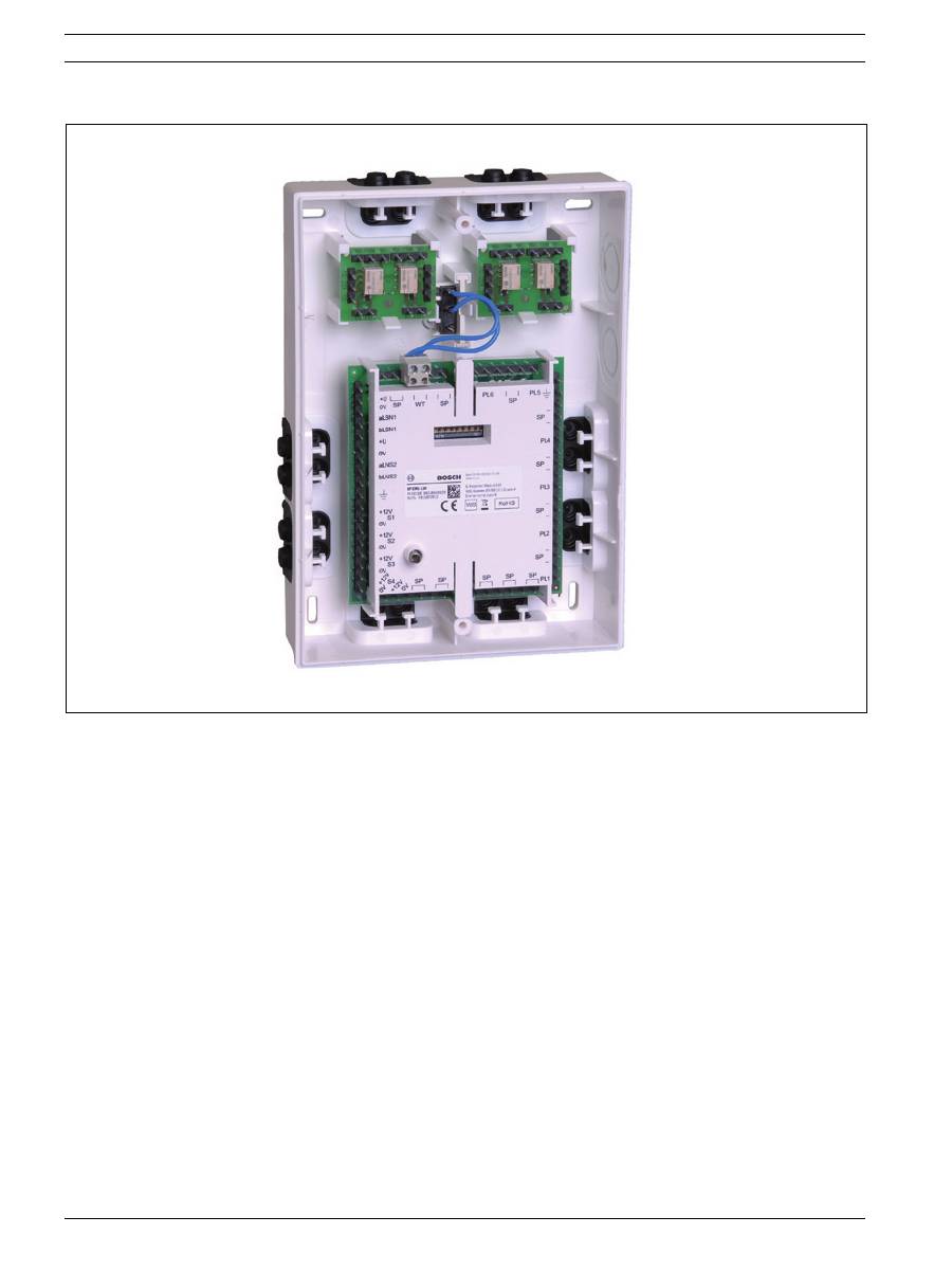
Funktionsbeschreibung
Das Expansions Modul LSN dient zur Anschaltung von 6 Meldergruppen (GLT-Melder oder Überwachungskontakt-
Eingänge), zum Steuern (4 Steuerausgänge) bzw. zur Anschaltung von Schalteinrichtungen (z.B. NBS 10) mit Sys-
temkomponenten an das Lokale SicherheitsNetzwerk LSN. Das Expansions Modul LSN wurde zur Anschaltung an
LSN-Zentralen z.B. MAP 5000 entwickelt und bietet die erweiterte Funktionalität der LSN-improved-Technologie.
Über den integrierten DIP-Schalter kann der LSN-Modus "classic" gewählt werden (Auslieferungszustand), womit
eine Anschaltung an alle klassischen LSN-Notrufmelderzentralen wie NZ 300 LSN, UEZ 2000 LSN und UGM 2020
möglich ist. In das Gehäuse des Expansions Modul können optional max. 2 x IMS-RM Relaismodule eingebaut wer-
den (pro Relaismodul = 2 Relais, je Relais 2 Umschaltkontakte), wenn aufgrund des hohen Strombedarfs der ange-
schalteten Steuerelemente diese nicht direkt vom Expansions Modul angesteuert werden können, oder um
potentialfreies Schalten zu ermöglichen. Bei Bedarf kann ein Wandabreißkotakt eingesetzt werden (optional).
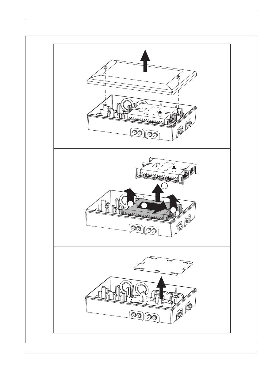
Montage
1.
Montagevorbereitung:
siehe Bild 1, Seite 5
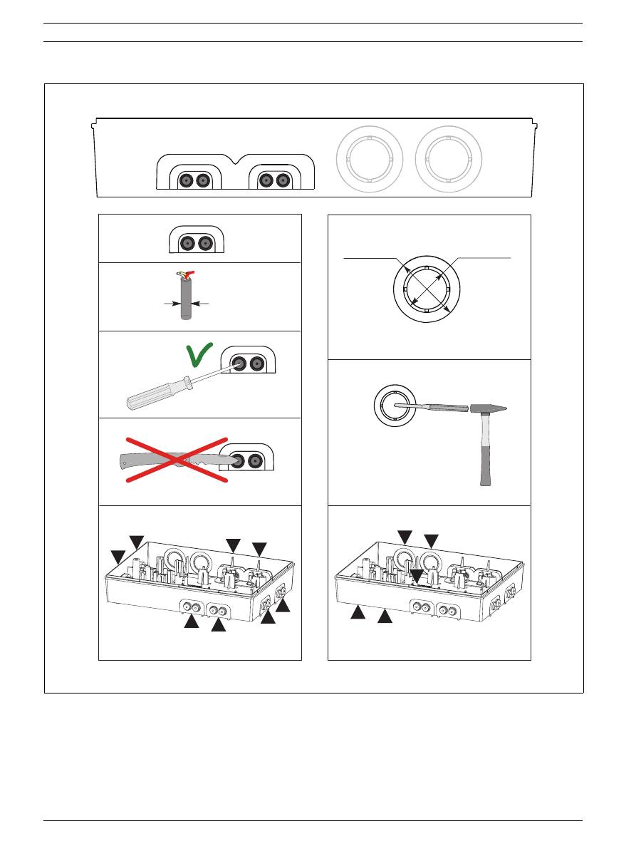
2.
Kabeleinführungen:
siehe Bild 2, Seite 6
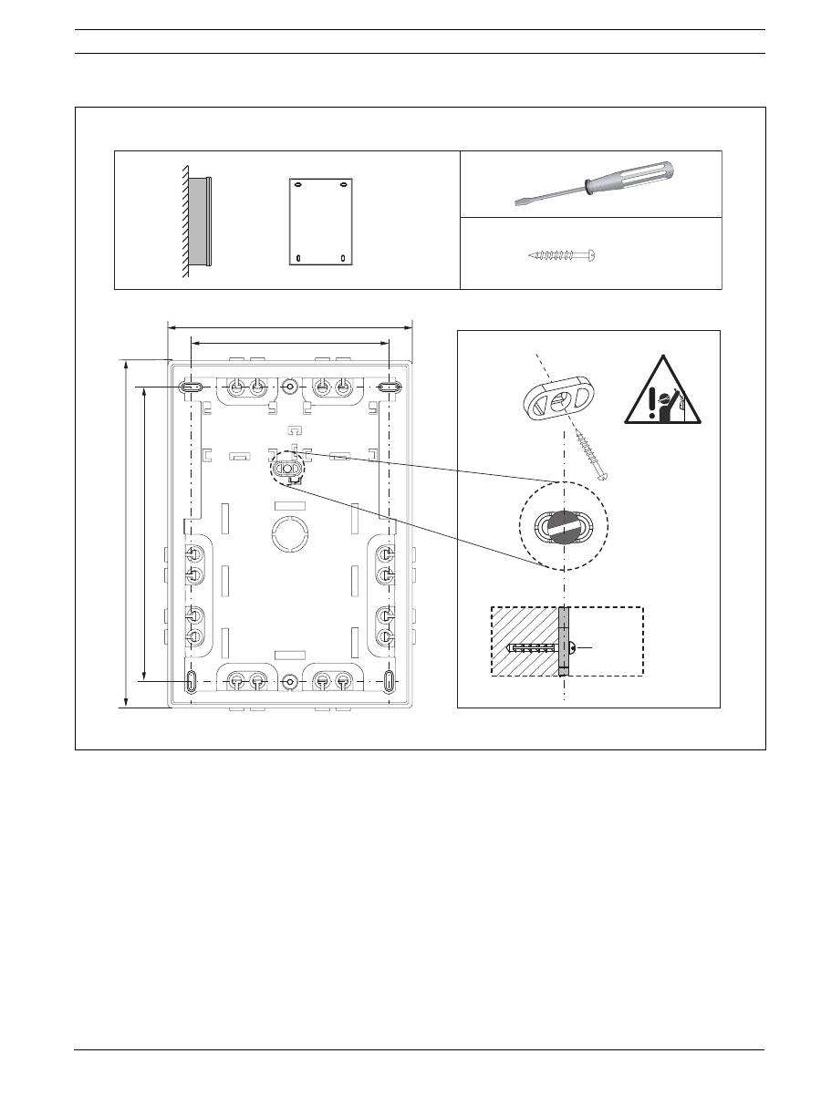
3.
Geräteunterteil und Schraube für Wandabreißkontakt (optional):
siehe Bild 3, Seite 7
4.
Anschlussklemmen, Relaismodul (optional) und Wandabreißkontakt (optional):
siehe Bild 4, Seite 8
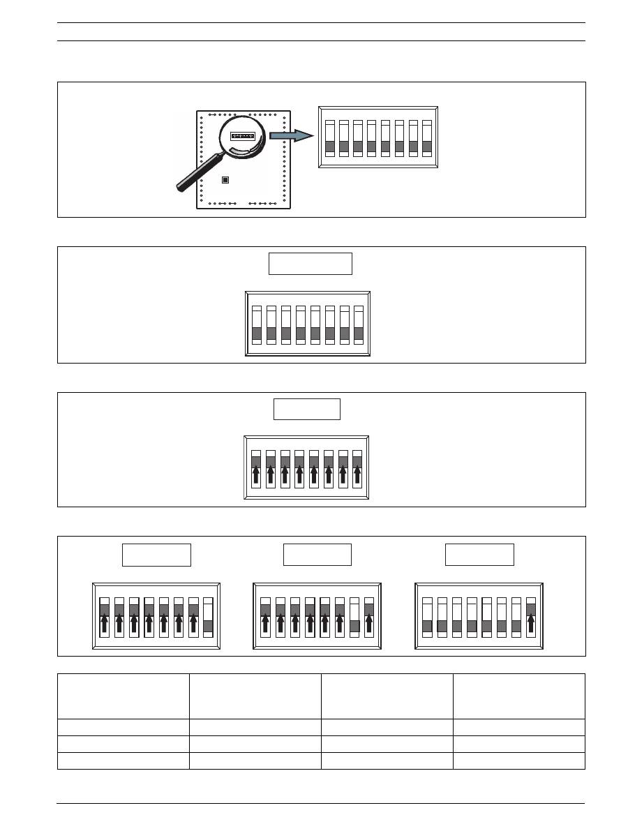
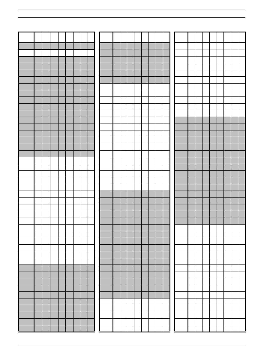
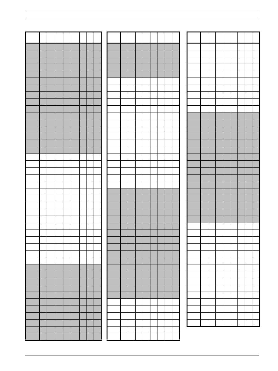
Adresseinstellung
Die Adresse des Expansions Modul wird über die 8 DIP-Schalter auf der Anschalteplatine mit einem geeigneten spit-
zen Gegenstand eingestellt.
5.
Die DIP-Schalterstellungen für alle zugelassenen Adressen sind in den Abbildungen und nachfolgende Tabellen
aufgeführt (1 = on, 0 = off ):
siehe Bild 5, Seite 9
und nachfolgende
Tabellen
.
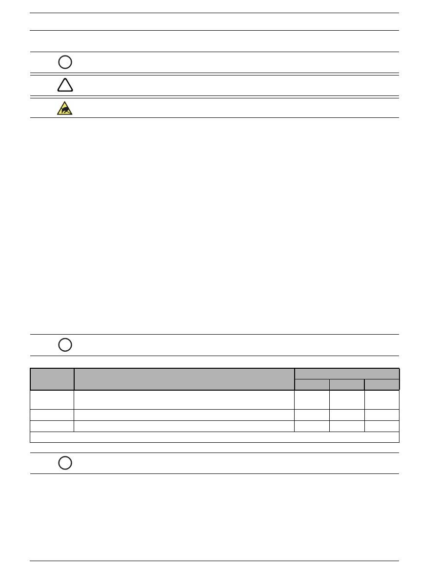
i
HINWEIS!
Installation nur von autorisiertem Fachpersonal durchführen!
!
WARNUNG!
Stromführende Bauteile und abisolierte Kabel! Verletzungsgefahr durch
Stromschlag. Bei Anschlussarbeiten muss die Anlage stromlos sein.
VORSICHT!
Elektrostatische Entladung (ESD)! Elektronische Bauteile können beschädigt
werden. Erdungsarmband anlegen oder andere geeignete Maßnahmen ergreifen.
i
HINWEIS!
Ab Werk ist die Adresse "255" eingestellt (alle DIP-Schalter auf "on")!
Adresse
(A)
Betriebsart (Modus)
Netzwerstruktur
Ring
Stich
T-Abzweig
255 = CL
Automatische Adressvergabe im LSN-Modus "classic"
(Adressbereich: max. 127)
x
x
-
0
Automatische Adressvergabe im LSN-Modus "improved version"
x
x
-
1 ... 254
Manuelle Adressvergabe im LSN-Modus "improved version"
x
x
x
x = möglich, - = nicht möglich
i
HINWEIS!
Es ist nicht zulässig, verschiedene Betriebsarten (Modi) in einem Ring/Stich/T-
Abzweig nebeneinander anzuwenden!

ISP-EMIL-120 Expansions Modul LSN
| de
17
Bosch Sicherheitssysteme GmbH
Installationsanleitung
F.01U.076.548 | V3 | 2008.10
Anschaltungen
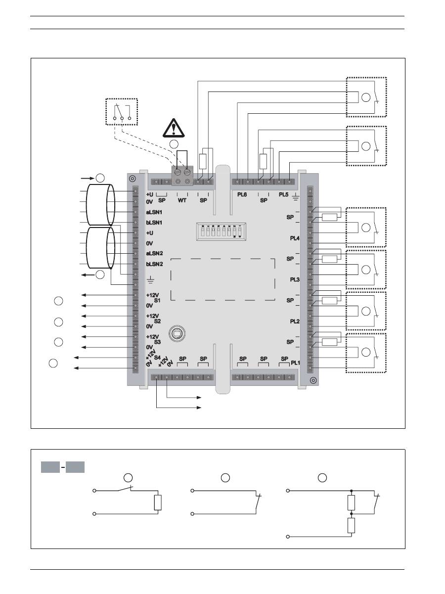
6.
Anschaltung von GLT-Meldern und Wandabreißkontakt (optional):
siehe Bild 6, Seite 12
a.
LSN kommend und gehend sind vertauschbar. Der Kabelschirm muss beidseitig aufgelegt werden.
b.
Bei Anschaltung des optionalen Wandabreißkontaktes Brücke WT (57 + 58) entfernen. Wird der Wandab-
reißkontakt nicht angeschlossen, bleibt die Brücke WT (57 + 58) gesteckt.
c.
Maximal 20 Melder der gleichen Bauart sind auf einer Primärleitung anschaltbar (VdS). Endwiderstand
nach dem letzten Melder einschleifen.
d.
Open Collector, 0 V wird geschaltet.
e.
Open Collector, 12 V wird geschaltet.
7.
Anschaltevarianten Primärleitungen PL 1 - PL 6:
siehe Bild 7, Seite 12
a.
Notruflinie mit Endwiderstand 12k1
b.
Kontaktlinie ohne Endwiderstand
c.
Notruflinie mit doppelten Endwiderstand 12k1
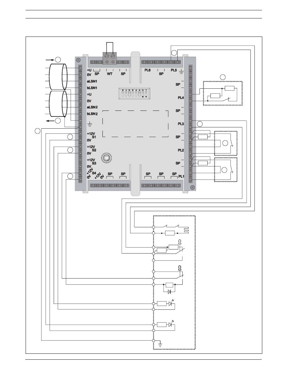
8.
Anschaltung einer Schalteinrichtung (z.B. NBS 10) und zugehörige Systemkomponenten:
siehe Bild 8, Seite 13
a.
LSN kommend und gehend sind vertauschbar. Kabelschirm muss bei Ringbildung beidseitig aufgelegt wer-
den.
b.
Kabelschirm (Adernfarbe: 10 = weiß/grün und braun/grün)
c.
Blockschloßanzeige LED1 "BLL" (Adernfarbe: 11 = rot, 12 = rosa)
d.
Blockschloßlanzeige LED2 "BLA" (Adernfarbe: 13 = grün, 14 = grau)
e.
Blockschloßmagnet "BSM" (Adernfarbe: 17 = gelb, 18 = blau/rot)
f.
Blockschloß Sabotagemeldergruppe (Adernfarbe: 49 = weiß, 50 = braun)
g.
z.B. Geistige Schalteinrichtung
h.
Blockschloß Primärleitung (Adernfarbe: 39 = schwarz, 40 = blau)
i.
z.B. Türkontakt
j.
z.B. Riegelkontakt
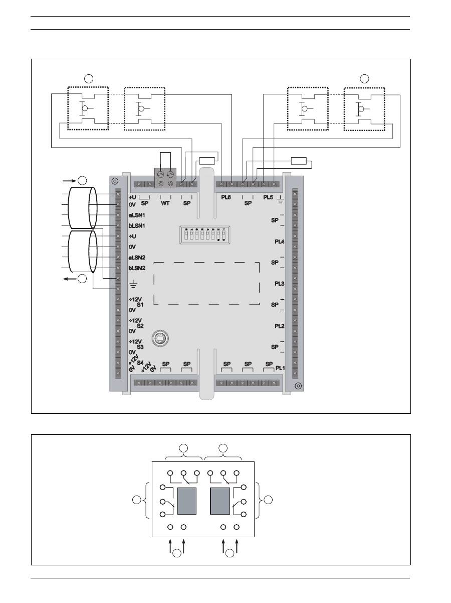
9.
Anschaltung Liniengespeiste Glasbruchmelder:
siehe Bild 9, Seite 14
a.
LSN kommend und gehend sind vertauschbar. Der Kabelschirm muss beidseitig aufgelegt werden.
b.
Maximal 20 Glasbruchmelder sind auf Primärleitung PL 5 und PL 6 anschaltbar (VdS). Endwiderstand nach
dem letzten Melder einschleifen. Im Alarmfall werden max. 3 Melder unterstützt. Ruhestrom <1 µA, Alarm-
strom max. 4 mA bei 6 V
10. Anschaltung optionales IMS-RM Relaismodul:
siehe Bild 10, Seite 14
a.
Schalteingang Relais 1 (Ansteuerung von Steuerausgang S1 - S4)
b.
Schalteingang Relais 2 (Ansteuerung von Steuerausgang S1 - S4)
c.
Umschaltkontakte Relais 1
d.
Umschaltkontakte Relais 2

18
de |
ISP-EMIL-120 Expansions Modul LSN
F.01U.076.548 | V3 | 2008.10
Installationsanleitung
Bosch Sicherheitssysteme GmbH
Anschlussbelegung
Nr.
Anschlüsse
Funktionen
1
+U
Spanunngsversorgung 9,0 bis 30 V, 1 und 5 intern verbunden
2
0V
Spanunngsversorgung 0 V, 2 und 6 intern verbunden
3/4
aLSN1/bLSN1
LSN kommend
5
+U
Spanunngsversorgung 9,0 bis 30 V, 5 und 1 intern verbunden
6
0V
Spanunngsversorgung 0 V, 6 und 2 intern verbunden
7/8
aLSN2/bLSN2
LSN gehend
9/10
– Eingänge Erde für Kabelschirm (falls vorhanden) , 9 und 10 intern verbunden
– Kabelschirm von NBS 10, (Adernfarbe: 10 = weiß/grün und braun/grün)
11/12
+12 V/0 V
Steuerausgang S1
+12 V/0 V geschaltetes Minuspotential, maximaler Ausgangsstrom 20 mA
– z.B. Ansteuerung des Relaismoduls
– Blockschloßanzeige LED1 "BLL" bei NBS 10, (Adernfarbe: 11 = rot, 12 = rosa)
13/14
+12 V/0 V
Steuerausgang S2
+12 V/0 V geschaltetes Minuspotential, maximaler Ausgangsstrom 20 mA
– z.B. Ansteuerung des Relaismoduls
– Blockschloßanzeige LED2 "BLA" bei NBS 10, (Adernfarbe: 13 = grün, 14 = grau)
15/16
+12 V/0 V
Steuerausgang S3
+12 V/0 V geschaltetes Minuspotential, maximaler Ausgangsstrom 20 mA,
z.B. Ansteuerung des Relaismoduls
17/18
+12 V/0 V
Steuerausgang S4
+12 V/0 V geschaltetes Pluspotential, maximaler Ausgangsstrom 100 mA
– z.B. Ansteuerung des Relaismoduls
– Blockschloßmagnet "BSM" bei NBS 10, (Adernfarbe: 17 = gelb, 18 = blau/rot)
19/20
+12 V/0 V
Ausgang
Spannungsversorgung für externe Verbraucher, Ausgangsstrom maximal 100 mA
21/22
SP
freie Verteiler zum Durchschleifen, 21 und 22 intern verbunden
23/24
SP
freie Verteiler zum Durchschleifen, 23 und 24 intern verbunden
25/26
SP
freie Verteiler zum Durchschleifen, 25 und 26 intern verbunden
27/28
SP
freie Verteiler zum Durchschleifen, 27 und 28 intern verbunden
29/30
SP
freie Verteiler zum Durchschleifen, 29 und 30 intern verbunden
31/32
PL 1
Primärleitung zur Anschaltung Meldergruppe 1
33/34
SP
z.B. Anschlüsse zum Einschleifen eines externen Endwiderstandes
35/36
PL 2
Primärleitung zur Anschaltung Meldergruppe 2
37/38
SP
z.B. Anschlüsse zum Einschleifen eines externen Endwiderstandes
39/40
PL 3
– Primärleitung zur Anschaltung Meldergruppe 3
– Blockschloß Primärleitung bei NBS 10, (Adernfarbe: 39 = schwarz, 40 = blau)
– Geistige Schalteinrichtung
41/42
SP
z.B. Anschlüsse zum Einschleifen eines externen Endwiderstandes
43/44
PL 4
– Primärleitung zur Anschaltung Meldergruppe 4
– Geistige Schalteinrichtung
45/46
SP
z.B. Anschlüsse zum Einschleifen eines externen Endwiderstandes
47/48
Eingänge Erde für Kabelschirm (falls vorhanden) , 47 und 48 intern verbunden
49/50
PL 5
– Primärleitung zur Anschaltung Meldergruppe 5 oder
– Anschaltung von Liniengespeisten Glasbruchmeldern
– Blockschloß Sabotagemeldergruppe bei NBS 10, (Adernfarbe: 49 = weiß, 50 =
braun)
51/52
SP
z.B. Anschlüsse zum Einschleifen eines externen Endwiderstandes
53/54
PL 6
– Primärleitung zur Anschaltung Meldergruppe 6
– Anschaltung von Liniengespeisten Glasbruchmeldern
55/56
SP
z.B. Anschlüsse zum Einschleifen eines externen Endwiderstandes
57/58
WT
Anschaltung des optionaler Wandabreißkontaktes. Wird der Wandabreißkontakt nicht
angeschlossen, bleibt die Brücke WT (57 + 58) gesteckt.
59/60
SP
freie Verteiler zum Durchschleifen, 59 und 60 intern verbunden

ISP-EMIL-120 Expansions Modul LSN
| de
19
Bosch Sicherheitssysteme GmbH
Installationsanleitung
F.01U.076.548 | V3 | 2008.10
Technische Daten
Betriebsspannung / Stromaufnahme
– Betriebsspannung
LSN-Teil
15 bis 33 V DC
restliche Funktionen
9,0 bis 30 V DC
– Stromaufnahme
LSN-Teil
4,95 mA
restliche Funktionen
- max. 370 mA bei 12 V
- max. 180 mA bei 28 V
Primärleitungen PL 1 - PL 6
– Anschaltmöglichkeit
6 Meldergruppen als Überfall, Einbruch, Sabotage,
Veschluss oder Eingang patametrierbar
– Endwiderstand
R
E
= 12,1 k
Ω
– Unterbrechungsspannung
ca. 6 V
– Leitungswiderstand
max. 100
Ω
– Alarmkriterium
±40% vom Endwiderstand
– Ansprechzeit
< 200 ms
Steuerausgänge S1 - S3
– Prinzip
Open-Collector, aktiv 12 V, 0 V schaltend
– max. Spannung
max. 30 V
– Schaltspannung
< 1,4 V
– Schaltstrom
max. 20 mA
Steuerausgang S4
– Prinzip
12 V schaltend
– Schaltspannung
12,5 V ±5%
– Schaltstrom
max. 100 mA
Spannungsversorgung +12 V für externe Verbraucher
– Ausgangsspannung
+12,5 V DC ±5%
– Ausgangsstrom
max. 100 mA
Bei Anschaltung einer Schalteinrichtung (z.B. NBS 10 / Geistige Schalteinrichtung)
– PL 1, 2, 5, 6 und S 1 - S 4
siehe oben
– Primärleitung PL 3
Blockschloss oder Geistige Schalteinrichtung
– Primärleitung PL 4
Geistige Schalteinrichtung
– Endwiderstände Blockschloss Primärleitung PL 3
R
E
= 12,1 k
Ω
±1% (scharf)
R
E
= 12,1 k
Ω
II 3,92 k
Ω
±1% (unscharf)
– Endwiderstände Geistige Schalteinrichtug Primärlei-
tung PL 3 oder PL 4
R
E
= 12,1 k
Ω
±1% (GS nicht gültig)
R
E
= 12,1 k
Ω
II 3,92 k
Ω
±1% (GS gültig)
Umgebungsbedingungen / Gehäuse
– Zulässige Betriebstemperatur
-0 °C ... +55 °C
– Zulässige Lagertemperatur
-25 °C ... +75 °C
– Zulässige rel. Luftfeuchtigkeit
<93%, ohne Betauung
– Schutzart
IP 30
– Umweltklasse
II (VdS 2110)
– EMV-Störfestigkeit
EN 60950, EN 50130, VDS 2110
– EMV-Störaussendung
EN 61000-6-3
– Gehäusematerial und Farbe
ABS + PC-FR, signalweiß (RAL 9003)
– Gewicht
ca. 400 g
– Abmessungen (H x B x T)
200 x 140 x 48 mm
20
en |
ISP-EMIL-120 LSN Expansion Module
F.01U.076.548 | V3 | 2008.10
Installation manual
Bosch Sicherheitssysteme GmbH
Functional description
The LSN expansion module can be used to connect 6 detector zones (conventional detectors or monitoring
contact inputs), for control purposes (4 control outputs) or for connecting arming devices (e.g. NBS 10) with
system components to the local security network (LSN). The LSN Expansion Module has been developed for
connection to LSN control panels, e.g. MAP 5000, and provides the extended functionality of LSN improved
technology. The LSN mode "classic" can be selected via the integrated DIP switch (default setting), enabling
the connection of all classic LSN emergency call detector control panels such as NZ 300 LSN, UEZ 2000 LSN
and UGM 2020. A maximum of 2 x IMS-RM relay modules can optionally be installed in the expansion module
housing (2 relays per relay module, 2 switch contacts per relay), if the switched control elements cannot be
directly controlled from the expansion module due to the high current requirement, or to enable zero-potential
switching. A wall tamper contact can be installed, if required (optional).
Installation
1.
Installation preparation:
see Fig. 1, page 5
2.
Cable entry points:
see Fig. 2, page 6
3.
Device base and screw for wall tamper contact (optional):
see Fig. 3, page 7
4.
Connection terminals, relay module (optional) and wall tamper contact (optional):
see Fig. 4, page 8
Address setting
The address of the expansion module is set via the 8 DIP switches on the connector board using a suitable
pointed implement.
5.
The DIP switch settings for all permissible addresses are listed in the diagrams and the tables below
(1 = on, 0 = off):
see Fig. 5, page 9
and
tables
below.
i
NOTE!
Installation to be performed by authorized specialized personnel only!
!
WARNING!
Current-carrying components and isolated cable. Danger of injury
through electric shock. The system must be free of current when connecting.
CAUTION!
Electrostatic discharge (ESD) Electronic components may be damaged.
Attach grounding wrist strap or take other suitable measures.
i
NOTE!
The address "255" is set at the factory (all DIP switches set to "on").
Address
(A)
Operating mode (mode)
Network structure
Loop
Stub
T-branch
255 = CL
Automatic address assignment in "classic" LSN mode.
(Address range: max. 127)
x
x
-
0
Automatic address assignment in "improved version" LSN mode.
x
x
-
1 to 254
Manual address assignment in "improved version" LSN mode.
x
x
x
x = possible, - = not possible
i
NOTE!
Different operating modes must not be used next to one another
in loops/stubs/T-branches.
