Bosch S 500 A Professional: инструкция
Раздел: Инструмент, электроинструмент, силовая техника
Тип:
Инструкция к Bosch S 500 A Professional
Robert Bosch GmbH
Power Tools Division
70745 Leinfelden-Echterdingen
Germany
S 500 A Professional
www.bosch-pt.com
1 609 929 W61 (2010.06) T / 217 XXX
de Originalbetriebsanleitung
cs Původní návod k používání
cn 正本使用说明书
en Original instructions
sk Pôvodný návod na použitie
tw 正本使用說明書
fr Notice originale
hu Eredeti használati utasítás
es Manual original
ru Оригинальное руководство по
ko 사용 설명서 원본
pt Manual original
эксплуатации
th
หนังสือคู่มือการใช้งานฉบับต้นแบบ
it Istruzioni originali
uk Оригінальна інструкція з
id Petunjuk-Petunjuk untuk
nl Oorspronkelijke
експлуатації
Penggunaan Orisinal
gebruiksaanwijzing
ro Instrucţiuni originale
vi BΩng hõëng dÿn nguy›n bΩn
da Original brugsanvisning
bg Оригинална инструкция
ar
sv Bruksanvisning i original
sr Originalno uputstvo za rad
no Original driftsinstruks
sl Izvirna navodila
fa
fi Alkuperäiset ohjeet
hr Originalne upute za rad
el Πρωτότυπο οδηγιών χρήσης
et Algupärane kasutusjuhend
tr Orijinal işletme talimat
lv Instrukcijas oriģinālvalodā
pl Instrukcja oryginalna
lt Originali instrukcija
ΕΎϤϴϠόΗϞϴϐθΘϟΔϴϠλϷ
Ϡλ έΎ ίήσ ΎϤϨϫέ
OBJ_BUCH-117-003.book Page 1 Wednesday, June 9, 2010 11:30 AM
OBJ_BUCH-117-003.book Page 2 Wednesday, June 9, 2010 11:31 AM
2 |
Deutsch . . . . . . . . . . . . . . . . . . . . . . . . . . . . Seite 6
English . . . . . . . . . . . . . . . . . . . . . . . . . . . . . Page 12
Français . . . . . . . . . . . . . . . . . . . . . . . . . . . . Page 19
Español. . . . . . . . . . . . . . . . . . . . . . . . . . . . Página 26
Português. . . . . . . . . . . . . . . . . . . . . . . . . . Página 33
Italiano . . . . . . . . . . . . . . . . . . . . . . . . . . . . Pagina 39
Nederlands . . . . . . . . . . . . . . . . . . . . . . . . . Pagina 46
Dansk . . . . . . . . . . . . . . . . . . . . . . . . . . . . . . Side 52
Svenska . . . . . . . . . . . . . . . . . . . . . . . . . . . . Sida 57
Norsk . . . . . . . . . . . . . . . . . . . . . . . . . . . . . . Side 62
Suomi . . . . . . . . . . . . . . . . . . . . . . . . . . . . . . . Sivu 67
Ελληνικά . . . . . . . . . . . . . . . . . . . . . . . . . . . Σελίδα 73
Türkçe . . . . . . . . . . . . . . . . . . . . . . . . . . . . . Sayfa 80
Polski . . . . . . . . . . . . . . . . . . . . . . . . . . . . . Strona 85
Česky . . . . . . . . . . . . . . . . . . . . . . . . . . . . . Strana 92
Slovensky . . . . . . . . . . . . . . . . . . . . . . . . . . Strana 98
Magyar . . . . . . . . . . . . . . . . . . . . . . . . . . . . . Oldal 104
Русский . . . . . . . . . . . . . . . . . . . . . . . . Страница 110
Українська . . . . . . . . . . . . . . . . . . . . . . . Сторінка 117
Română . . . . . . . . . . . . . . . . . . . . . . . . . . . Pagina 124
Български . . . . . . . . . . . . . . . . . . . . . . Страница 130
Srpski . . . . . . . . . . . . . . . . . . . . . . . . . . . . . Strana 137
Slovensko. . . . . . . . . . . . . . . . . . . . . . . . . . . Stran 143
Hrvatski . . . . . . . . . . . . . . . . . . . . . . . . . Stranica 149
Eesti . . . . . . . . . . . . . . . . . . . . . . . . . . . . Lehekülg 155
Latviešu . . . . . . . . . . . . . . . . . . . . . . . . . Lappuse 161
Lietuviškai . . . . . . . . . . . . . . . . . . . . . . . Puslapis 167
中文 . . . . . . . . . . . . . . . . . . . . . . . . . . . . . . . . . . 页 173
中文. . . . . . . . . . . . . . . . . . . . . . . . . . . . . . . . . . 頁 178
한국어 . . . . . . . . . . . . . . . . . . . . . . . . . . . . . . . . . 면 183
ภาษาไทย . . . . . . . . . . . . . . . . . . . . . . . . . . . . . . หน้า 188
Bahasa Indonesia . . . . . . . . . . . . . . . . . . Halaman 194
Tiøng Vi·t . . . . . . . . . . . . . . . . . . . . . . . . . . . Trang 200
vv
vv
cc
cc
. . . . . . . . . . . . . . . . . . . . . . . . . . . . . . . 206
ΔΤϔλ
vÝ—U
. . . . . . . . . . . . . . . . . . . . . . . . . . . . . 211
ϪΤϔλ
1 609 929 W61 | (9.6.10) Bosch Power Tools
OBJ_BUCH-117-003.book Page 3 Wednesday, June 9, 2010 11:31 AM
3 |
18
18
1
18
2
3
4
5
17
6
19
16
21
7
20
8
22
1
9
11
10
11
15
14
1
S 500 A
13
Professional
12
1 609 929 W61 | (9.6.10) Bosch Power Tools
OBJ_BUCH-117-003.book Page 4 Wednesday, June 9, 2010 11:31 AM
4 |
BA
12
13
12
12
13
DC
23
24
25
1 609 929 W61 | (9.6.10) Bosch Power Tools
OBJ_BUCH-117-003.book Page 5 Wednesday, June 9, 2010 11:31 AM
5 |
FE
20
21
22
HG
2
26
27
3
17
6
8
7
8
28
1 609 929 W61 | (9.6.10) Bosch Power Tools
OBJ_BUCH-117-003.book Page 6 Wednesday, June 9, 2010 11:31 AM
6 | Deutsch
de
Sicherheitshinweise
f Vermeiden Sie eine abnormale Körperhal-
tung. Sorgen Sie für einen sicheren Stand
WARNUNG
Lesen Sie alle Sicherheitshin-
und halten Sie jederzeit das Gleichgewicht.
weise und Anweisungen, die
Dadurch können Sie das Elektrowerkzeug in
mit dem Bohrständer oder der Bohrmaschine
unerwarteten Situationen besser kontrollie-
geliefert wurden. Versäumnisse bei der Einhal-
ren.
tung der Sicherheitshinweise und Anweisungen
f Pflegen Sie den Bohrständer mit Sorgfalt.
können elektrischen Schlag, Brand und/oder
Kontrollieren Sie, ob bewegliche Gerätetei-
schwere Verletzungen verursachen.
le einwandfrei funktionieren und nicht
Bewahren Sie alle Sicherheitshinweise und
klemmen, ob Teile gebrochen oder so be-
Anweisungen für die Zukunft auf.
schädigt sind, dass die Funktion des Bohr-
f Ziehen Sie den Stecker aus der Steckdose,
ständers beeinträchtigt ist. Lassen Sie
bevor Sie Geräteeinstellungen vornehmen
beschädigte Teile vor dem Einsatz des
oder Zubehörteile wechseln. Unbeabsichtig-
Bohrständers reparieren. Viele Unfälle ha-
ter Start von Bohrmaschinen ist die Ursache
ben ihre Ursache in schlecht gewarteten
einiger Unfälle.
Geräten.
f Bauen Sie vor der Montage der Bohrmaschi-
f Bewahren Sie unbenutzte Bohrständer
ne den Bohrständer richtig auf. Richtiger Zu-
außerhalb der Reichweite von Kindern auf.
sammenbau ist wichtig, um die einwandfreie
Lassen Sie Personen das Gerät nicht benut-
Funktion zu gewährleisten.
zen, die mit diesem nicht vertraut sind oder
diese Anweisungen nicht gelesen haben.
f Befestigen Sie die Bohrmaschine sicher am
Geräte sind gefährlich, wenn sie von unerfah-
Bohrständer, bevor Sie sie benutzen. Ein
renen Personen benutzt werden.
Verrutschen der Bohrmaschine im Bohrstän-
der kann zum Verlust der Kontrolle führen.
f Lassen Sie den Bohrständer nur von qualifi-
ziertem Fachpersonal und nur mit Original-
f Befestigen Sie den Bohrständer auf einer
Ersatzteilen reparieren. Damit wird sicher-
festen, ebenen Fläche. Wenn der Bohrstän-
gestellt, dass die Sicherheit des Gerätes er-
der verrutschen oder wackeln kann, kann die
halten bleibt.
Bohrmaschine nicht gleichmäßig und sicher
f Fassen Sie den Bohrständer an den isolier-
geführt werden.
ten Griffflächen an, wenn Sie Arbeiten aus-
f Überlasten Sie den Bohrständer nicht und
führen, bei denen das Einsatzwerkzeug ver-
verwenden Sie ihn nicht als Leiter oder Ge-
borgene Stromleitungen oder das eigene
rüst. Überlastung oder Stehen auf dem Bohr-
Netzkabel treffen kann. Der Kontakt mit ei-
ständer kann dazu führen, dass sich der
ner spannungsführenden Leitung kann auch
Schwerpunkt des Bohrständers nach oben
Metallteile des Bohrständers unter Span-
verlagert und er umkippt.
nung setzen und zu einem elektrischen
f Halten Sie Ihren Arbeitsbereich sauber und
Schlag führen.
gut beleuchtet. Unordnung oder unbeleuch-
f Die Sicherheits- und Arbeitshinweise für
tete Arbeitsbereiche können zu Unfällen füh-
die eingesetzte Bohrmaschine und das ver-
ren.
wendete Zubehör sind strikt zu beachten!
f Entfernen Sie Einstellwerkzeuge oder
f Sichern Sie vor allen Arbeiten an Bohrstän-
Schraubenschlüssel, bevor Sie das Gerät
der oder Bohrmaschine, in Arbeitspausen
einschalten. Ein Werkzeug oder Schlüssel,
sowie bei Nichtgebrauch den Bohrständer
der sich in einem drehenden Geräteteil befin-
durch Einrasten der Vorschubarretierung 3
det, kann zu Verletzungen führen.
gegen unbeabsichtigtes Bewegen.
1 609 929 W61 | (9.6.10) Bosch Power Tools
OBJ_BUCH-117-003.book Page 7 Wednesday, June 9, 2010 11:31 AM
Deutsch | 7
Funktionsbeschreibung
19 Winkelskala
20 Arretierknopf der Bohrwinkel-Verstellung
Lesen Sie alle Sicherheitshinweise
21 Oberer Knebelgriff der Bohrwinkel-Verstel-
und Anweisungen. Versäumnisse
lung
bei der Einhaltung der Sicherheits-
hinweise und Anweisungen können
22 Unterer Knebelgriff der Bohrwinkel-Verstel-
elektrischen Schlag, Brand und/oder
lung
schwere Verletzungen verursachen.
23 Mauerwerksdübel*
Bitte klappen Sie die Aufklappseite mit der Dar-
24 Schnellspannspindel*
stellung des Bohrständers auf, und lassen Sie
25 Flügelmutter*
diese Seite aufgeklappt, während Sie die Be-
26 Gleitelemente
triebsanleitung lesen.
27 Innensechskantschrauben der Geräteauf-
nahme
Bestimmungsgemäßer Gebrauch
28 Stellschrauben der Geräteaufnahme
Der Diamantbohrständer ist zur Aufnahme von
*Abgebildetes oder beschriebenes Zubehör gehört
Bosch-Diamantbohrmaschinen bestimmt. Andere
nicht zum Standard-Lieferumfang. Das vollständige
Geräte dürfen nicht eingesetzt werden.
Zubehör finden Sie in unserem Zubehörprogramm.
Der Diamantbohrständer kann mithilfe von Dübel
oder Schnellspannsäule am Boden und an der
Technische Daten
Wand angebracht werden. In Kombination mit
den Diamantbohrmaschinen GDB 1600 WE oder
Diamantbohrständer S 500 A
GDB 1600 DE kann der Bohrständer auch über
Professional
Kopf befestigt werden.
Sachnummer
0 601 190 025
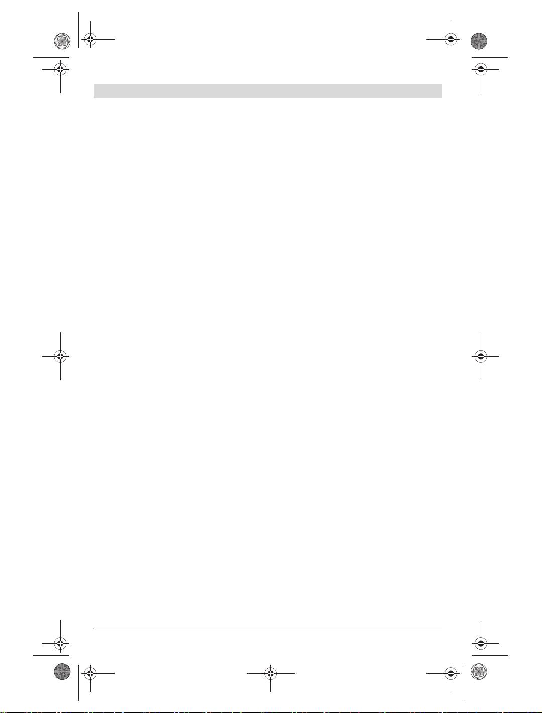
Abgebildete Komponenten
Maße
–Höhe
mm
1010
Die Nummerierung der abgebildeten Komponen-
–Breite
mm
280
ten bezieht sich auf die Darstellung des Bohr-
– Tiefe
mm
465 (400*)
ständers auf der Grafikseite.
– Bohrsäulenlänge
mm
1000
1 Transportgriff
Bohrhub max.
mm 500
2 Bohrsäule
max. Bohrdurchmesser
3 Vorschubarretierung
in Beton mit
4 Libelle für senkrechtes Ausrichten
– GDB 1600 WE**
mm
102
5 Libelle für waagerechtes Ausrichten
– GDB 2500 WE***
mm
212
6 Oberer Knebelgriff an der Geräteaufnahme
max. Bohrdurchmesser
7 Unterer Knebelgriff an der Geräteaufnahme
in Mauerwerk mit
8 Geräteaufnahme
– GDB 1600 WE/DE**
mm
152
9 Zahnstange
– GDB 2500 WE***
mm
152
10 Bohrloch-Mittenanzeiger
Gewicht entsprechend
11 Nivellierschraube
EPTA-Procedure
12 Stützwinkel
01/2003
kg 12,5
13 Rändelschraube für Stützwinkel
* mit nach hinten montierten Stützwinkeln
14 Sechskantschraube für Transporträder
** mit Saugkopf
15 Transporträder
*** auch mit Wasserfangring (Zubehör) möglich
16 Arretierstift der Vorschubkurbel
Bitte beachten Sie die Sachnummer auf dem Typen-
17 Vorschubkurbel
schild Ihres Bohrständers. Die Handelsbezeichnungen
18 Handgriff (isolierte Grifffläche)
einzelner Bohrständer können variieren.
Bosch Power Tools 1 609 929 W61 | (9.6.10)
OBJ_BUCH-117-003.book Page 8 Wednesday, June 9, 2010 11:31 AM
8 | Deutsch
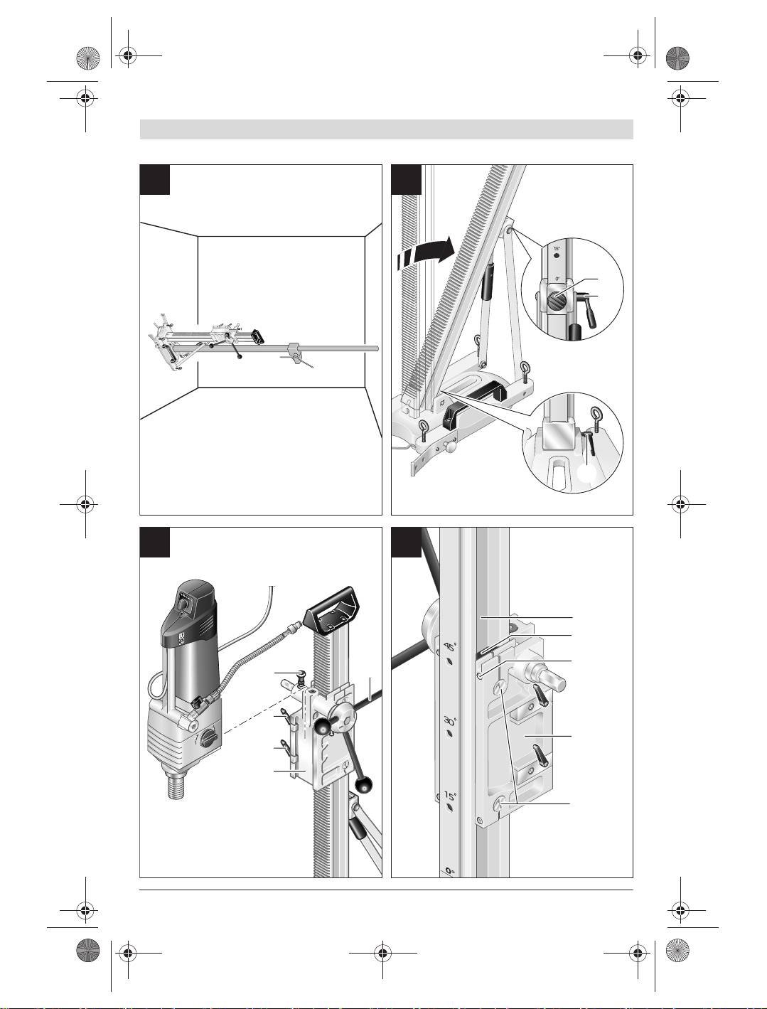
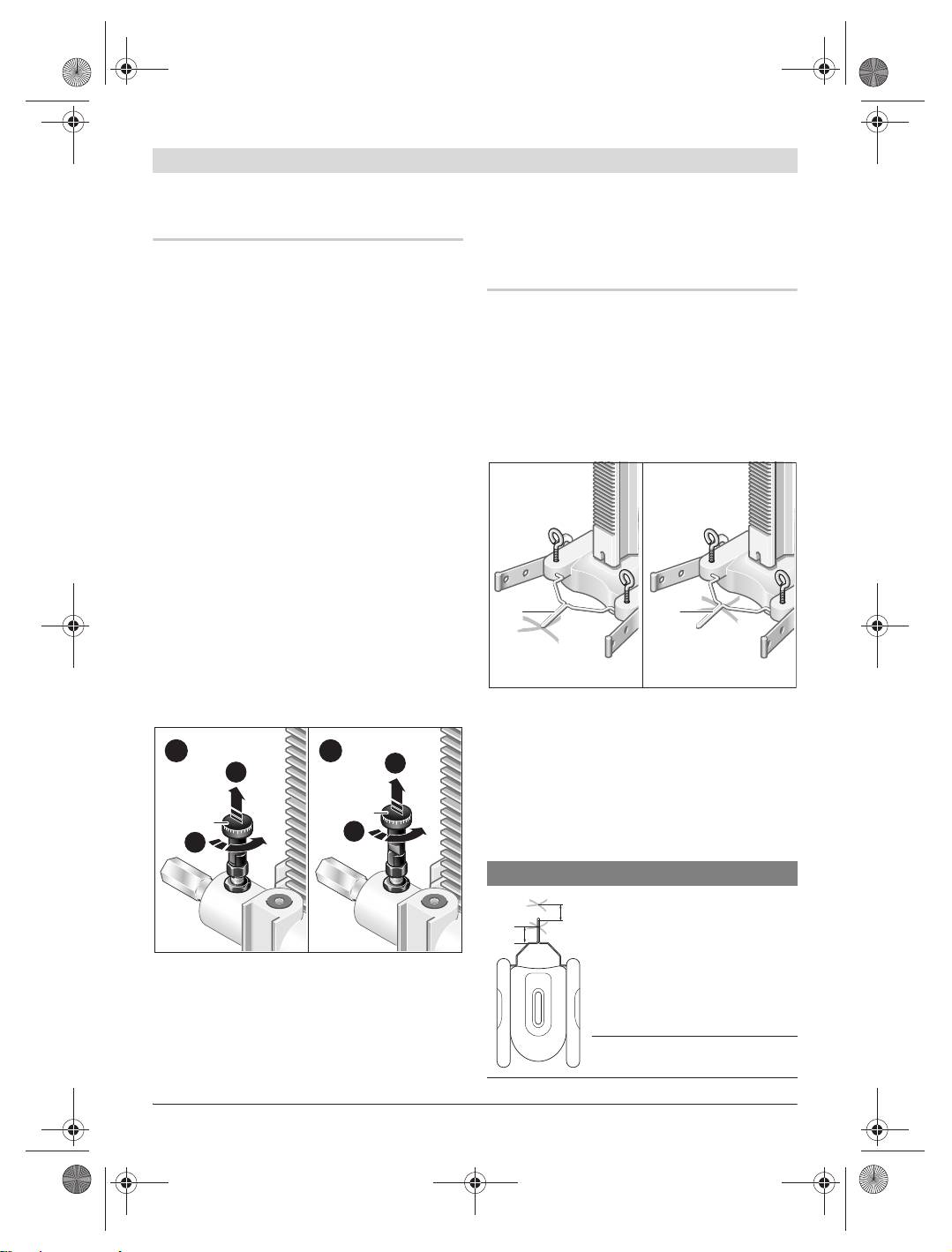
Vorschubkurbel
Konformitätserklärung
Drücken Sie den Arretierstift 16 an der Vor-
Wir erklären in alleiniger Verantwortung, dass
schubkurbel und halten Sie ihn gedrückt. Schie-
das unter „Technische Daten“ beschriebene
ben Sie die Vorschubkurbel 17 je nach Bedarf
Produkt den Bestimmungen der Richtlinie
links oder rechts von der Geräteaufnahme 8 bis
2006/42/EG entspricht.
zum Anschlag auf.
Technische Unterlagen bei:
Lassen Sie den Arretierstift 16 los und prüfen
Robert Bosch GmbH, PT/ESC,
Sie die Vorschubkurbel auf festen Sitz.
D-70745 Leinfelden-Echterdingen
Dr. Egbert Schneider
Dr. Eckerhard Strötgen
1
2
Senior Vice President
Head of Product
A
A
Engineering
Certification
3
3
B
B
Robert Bosch GmbH, Power Tools Division
D-70745 Leinfelden-Echterdingen
Leinfelden, 22.04.2010
Montage
Blockieren Sie anschließend den Vorschub: Zie-
hen Sie die Vorschubarretierung 3 nach oben
Bohrständer montieren
(A), drehen Sie sie (B) und lassen Sie sie in Stel-
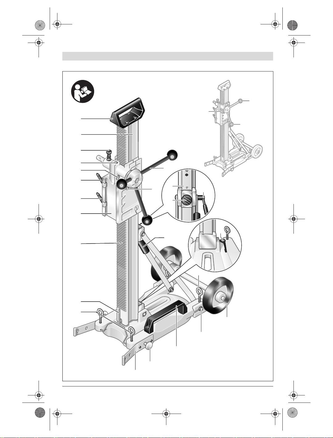
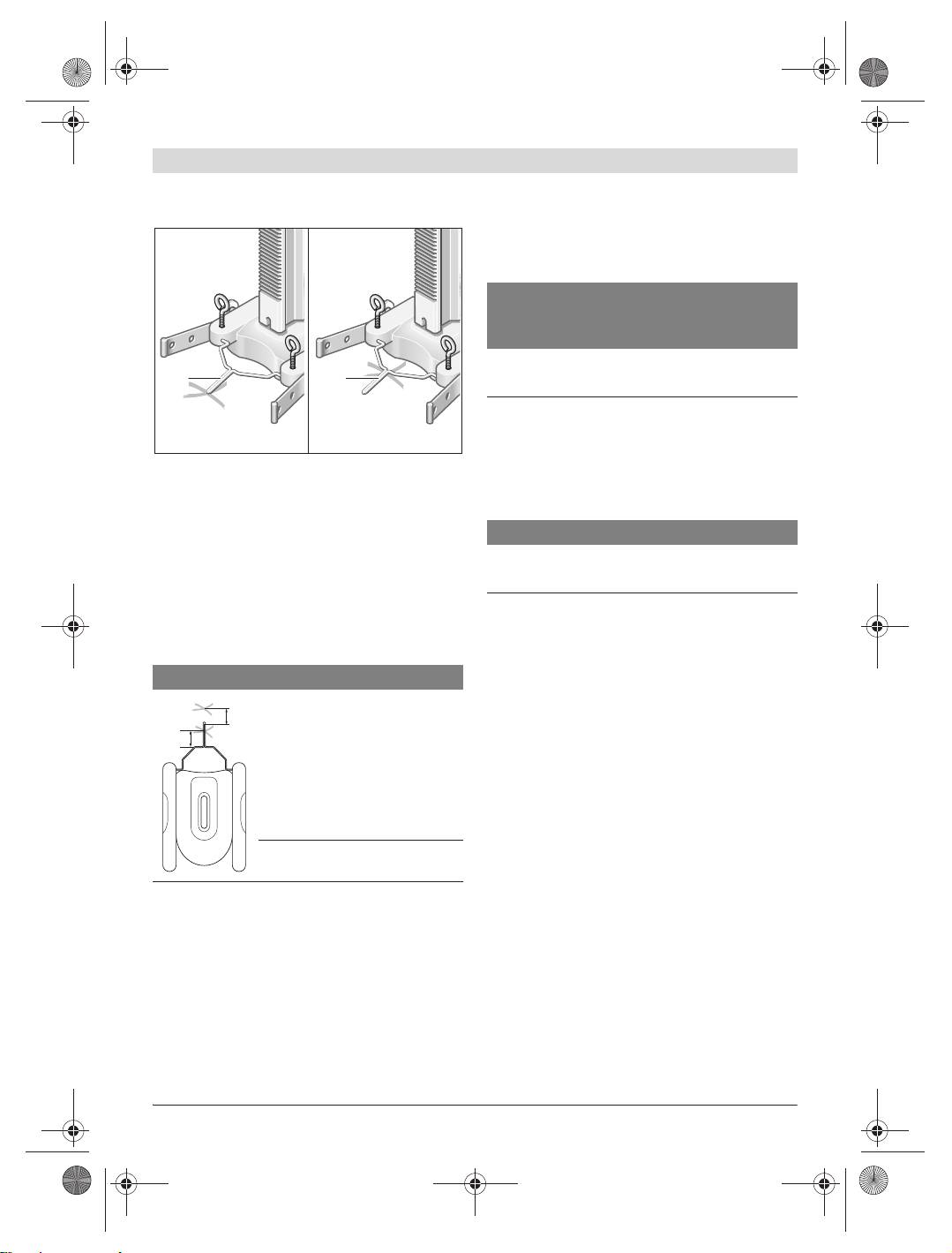
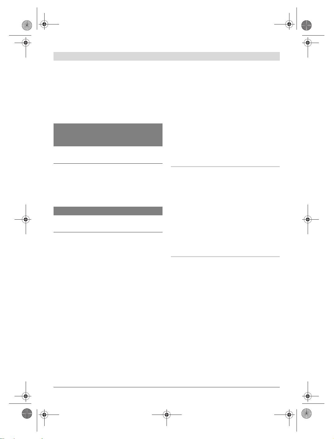
Stützwinkel
lung c einrasten. Drehen Sie bei Bedarf die Vor-
Sie können die Stützwinkel 12 in zwei Stellun-
schubkurbel 17 leicht, bis die Arretierung hör-
gen montieren:
bar einrastet.
– Die Grundstellung (siehe Bild A) ist notwen-
Lösen Sie den Vorschub nur zum Bohren: Ziehen
dig, wenn die GDB 2500 WE in den Bohrstän-
Sie die Vorschubarretierung 3 nach oben (A),
der eingesetzt und der Bohrständer nicht mit
drehen Sie sie (B) und lassen Sie sie in Stellung
Dübel oder Schnellspannsäule sicher befestigt
d einrasten.
ist.
– Die Platz sparende Stellung (siehe Bild B) ist
Transporträder
nur möglich bei Einsatz der GDB 1600 WE/DE
Schrauben Sie zum Transport des Bohrständers
oder bei sicher an der Wand befestigtem Bohr-
die Transporträder 15 mit den Sechskantschrau-
ständer. Die Montage des Wasserfangringes
ben 14 an den Seiten des Bohrständers fest.
(Zubehör) für die GDB 2500 WE ist in dieser
Stellung nicht möglich.
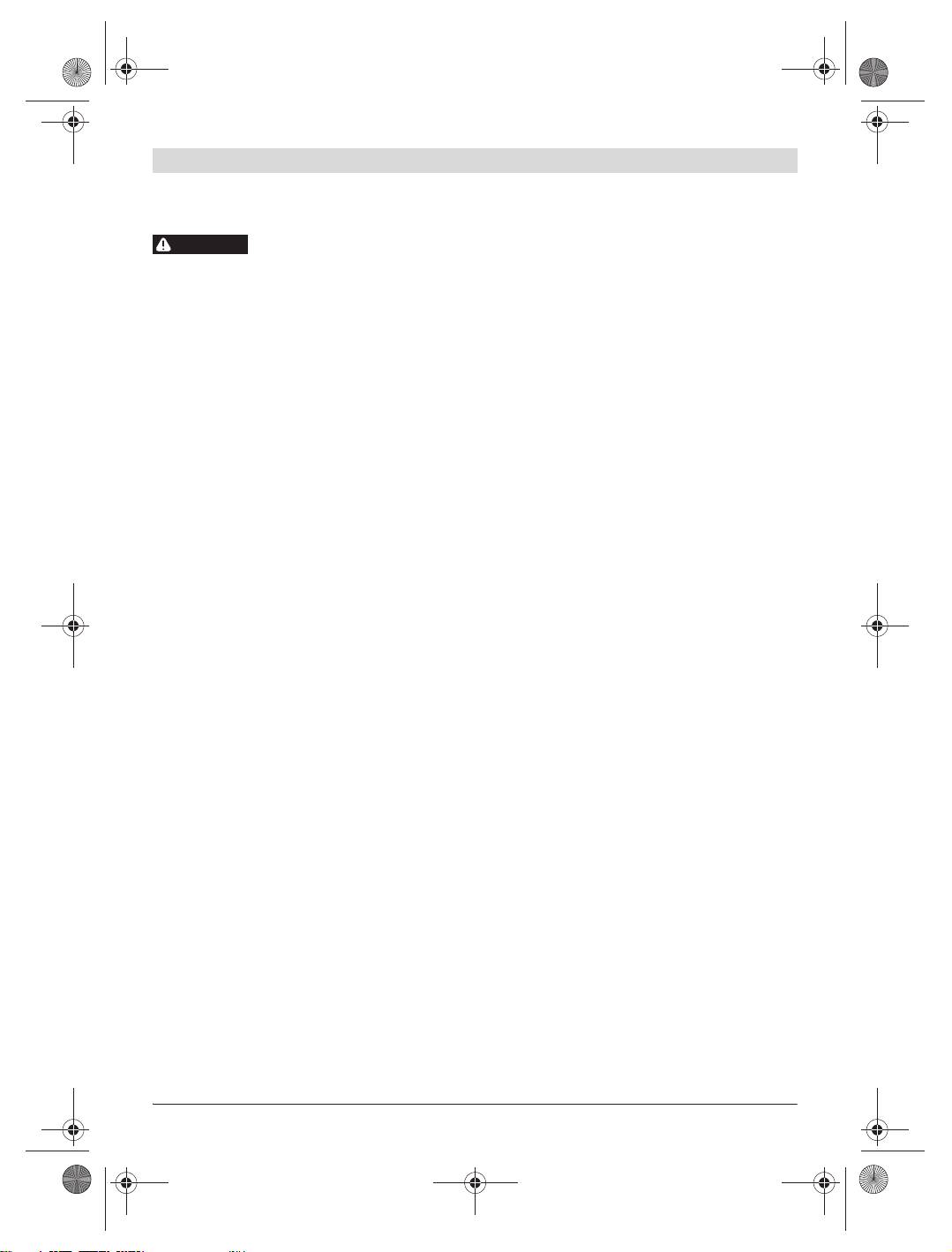
Bohrständer befestigen
Zum Wechsel zwischen beiden Stellungen lösen
Hinweis: Befestigen Sie den Bohrständer spiel-
Sie die Rändelschrauben 13, versetzen die
frei. So vermeiden Sie ein Verklemmen der Bohr-
Stützwinkel 12 in die gewünschte Position und
krone und damit Segmentabriss.
schrauben sie mit den Rändelschrauben wieder
Befestigen Sie je nach Art und Beschaffenheit
fest.
des Untergrundes den Bohrständer mit Dübel
oder Schnellspannsäule am geplanten Bohrloch.
1 609 929 W61 | (9.6.10) Bosch Power Tools
OBJ_BUCH-117-003.book Page 9 Wednesday, June 9, 2010 11:31 AM
Deutsch | 9
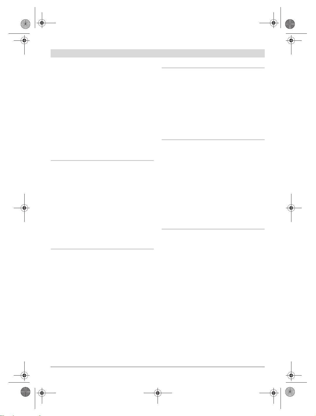
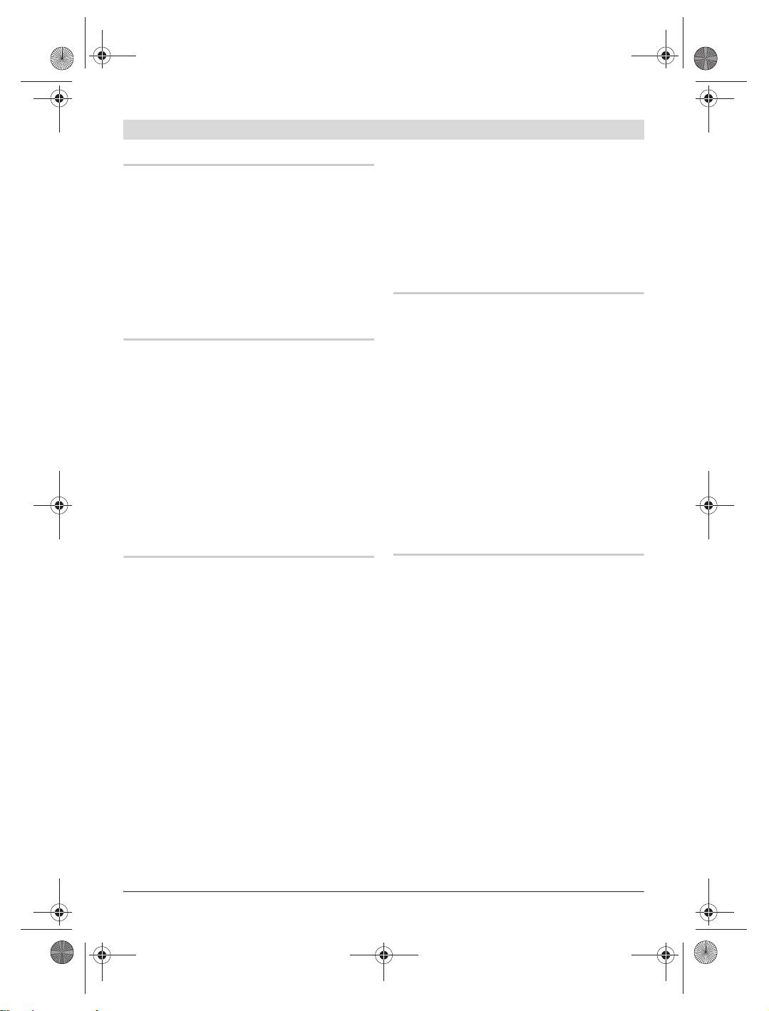
Bohrständer vor der Befestigung positionieren
Befestigung mit Dübel (siehe Bild C)
Bohren Sie für die Befestigung des Bohrstän-
ders mit Dübel (Zubehör) in Mauerwerk oder
Beton ein separates Befestigungsloch.
Abstand Dübelloch–Mitte des geplanten
Bohrlochs
optimal möglich
GDB 2500 WE 330 mm 310–380 mm
1010
GDB 1600 WE/DE 270 mm 250–320 mm
Vergrößern Sie bei Schrägbohrungen den Ab-
stand zwischen dem Dübelloch und der Mitte
GDB 2500 WE GDB 1600 WE/DE
des geplanten Bohrlochs um den Wert m (siehe
Klappen Sie den Bohrloch-Mittenanzeiger 10
„Bohrständer vor der Befestigung positionie-
aus. Bringen Sie bei Verwendung der
ren“).
GDB 2500 WE die Spitze des Bohrloch-Mitten-
Für das Dübelloch gelten folgende Maße:
anzeigers mit der angezeichneten Mitte des ge-
planten Bohrlochs zur Deckung. Bei Verwen-
Durchmesser Tiefe
dung der GDB 1600 WE/DE ist die Innenkante
Mauerwerk 20 mm 85 mm
des Bohrloch-Mittenanzeigers 10 der Bezugs-
Beton 15mm 50mm
punkt.
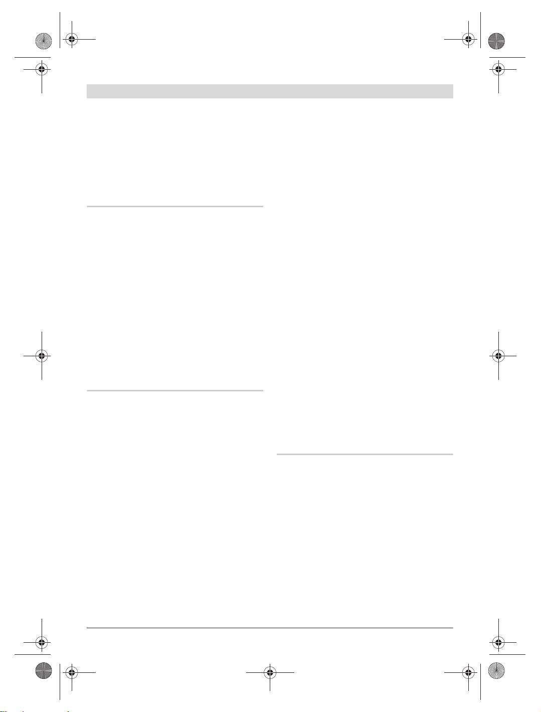
Verschieben Sie bei Schrägbohrungen den
Setzen Sie einen Betondübel mit Spreizkeil bzw.
Bohrständer um den Wert m von der Bohrloch-
einen Mauerwerksdübel 23 ein. Schrauben Sie
mitte:
die Schnellspannspindel 24 in den Dübel.
Setzen Sie den Bohrständer sowie eine Unter-
Bohrwinkel m
legscheibe auf und schrauben Sie sie mit der
Flügelmutter 25 an. Ziehen Sie die Flügelmutter
0° 0 mm
m*
nach der Nivellierung (siehe „Nivellieren“) mit
m**
einem Gabelschlüssel (Schlüsselweite 27 mm)
15° 30 mm
fest.
30° 80 mm
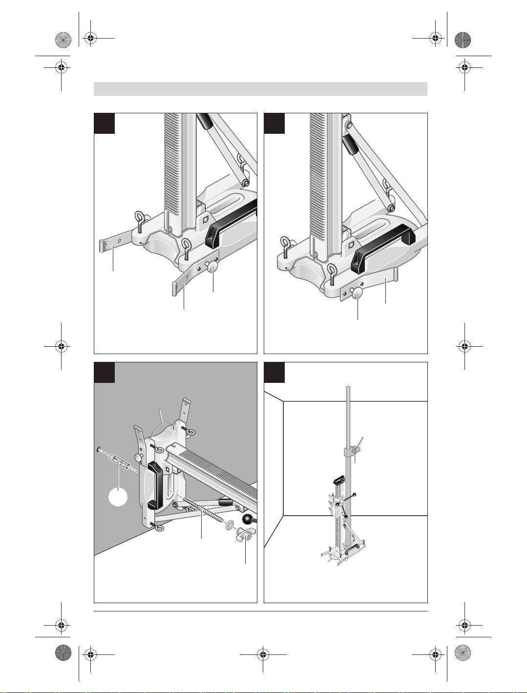
Befestigung mit einer Schnellspannsäule
(siehe Bild D und E)
45° 160 mm
Sie können den Bohrständer mit einer Bosch-
Schnellspannsäule (Zubehör) zwischen Boden
m* : GDB 2500 WE
und Decke oder zwischen zwei Wänden befesti-
m**: GDB 1600 WE/DE
gen. Der Spannbereich liegt zwischen 1,7 m und
Befestigen Sie den Bohrständer mit Dübel oder
3m.
Schnellspannsäule. Klappen Sie dann den Bohr-
Setzen Sie ein Ende der Schnellspannsäule auf
loch-Mittenanzeiger 10 ein.
die Bodenplatte des Bohrständers auf. Die Auf-
setzfläche für das andere Ende der Schnell-
spannsäule auf der Wand muss ausreichend
stabil und sicher gegen Verrutschen sein.
Für die Befestigung der Schnellspannsäule le-
sen und befolgen Sie deren Betriebsanleitung.
Bosch Power Tools 1 609 929 W61 | (9.6.10)
OBJ_BUCH-117-003.book Page 10 Wednesday, June 9, 2010 11:31 AM
10 | Deutsch
Nivellieren
Wasserabsaugung
Drehen Sie die Nivellierschrauben 11 einzeln so
weit ein bzw. heraus, bis die Libelle 4 (bei senk-
Um das beim Nassbohren aus der Bohrung aus-
rechter Montage) bzw. die Libelle 5 (bei waage-
tretende Wasser aufzufangen, benötigen Sie ei-
rechter Montage) exakt ausgerichtet ist.
nen Wasserfangring und einen Allzwecksauger
Fixieren Sie nun den Bohrständer fest mit Dübel-
(beide Zubehör).
befestigung oder Schnellspannsäule.
Die Auswahl des Wasserfangringes richtet sich
nach der eingesetzten Diamantbohrmaschine
(GDB 2500 WE oder GDB 1600 WE/DE).
Betrieb
Zur Montage des Wasserfangringes lesen und
befolgen Sie dessen Betriebsanleitung.
f Ziehen Sie nach jeder Verstellung am Bohr-
ständer Schrauben und Knebelgriffe wieder
gut fest und lassen Sie die Arretierungen
Arbeitshinweise
wieder einrasten.
f Beachten Sie zum Bohren die Betriebsanlei-
tung Ihrer Diamantbohrmaschine.
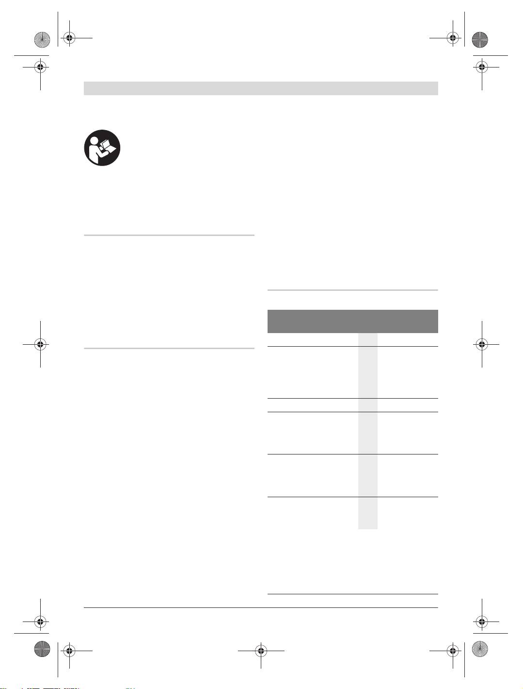
Bohrwinkel ändern (siehe Bild F)
Lösen Sie zum Bohren die Arretierung der Vor-
Lösen Sie den oberen Knebelgriff 21 und den
schubkurbel 17 (siehe „Vorschubkurbel“).
unteren Knebelgriff 22 der Winkelverstellung.
Drehen Sie mit der Vorschubkurbel die Bohrma-
Ziehen Sie den Arretierknopf 20. Stellen Sie den
schine bis zur gewünschten Bohrtiefe herunter.
Bohrständer auf einen der vier möglichen Bohr-
Drehen Sie danach zurück, bis die Bohrkrone
winkel (0°, 15°, 30° oder 45°) und lassen Sie
vollständig sichtbar ist.
den Arretierknopf in der entsprechenden Vertie-
fung der Bohrsäule einrasten.
Ziehen Sie die beiden Knebelgriffe 21 und 22
wieder fest.
Wartung und Service
f Der Bohrständer darf erst eingesetzt wer-
den, wenn beide Knebelgriffe der Winkel-
Wartung und Reinigung
verstellung wieder festgezogen sind.
Halten Sie die Zahnstange 9 und die Führungs-
flächen der Bohrsäule 2 stets sauber.
Diamantbohrmaschine einsetzen
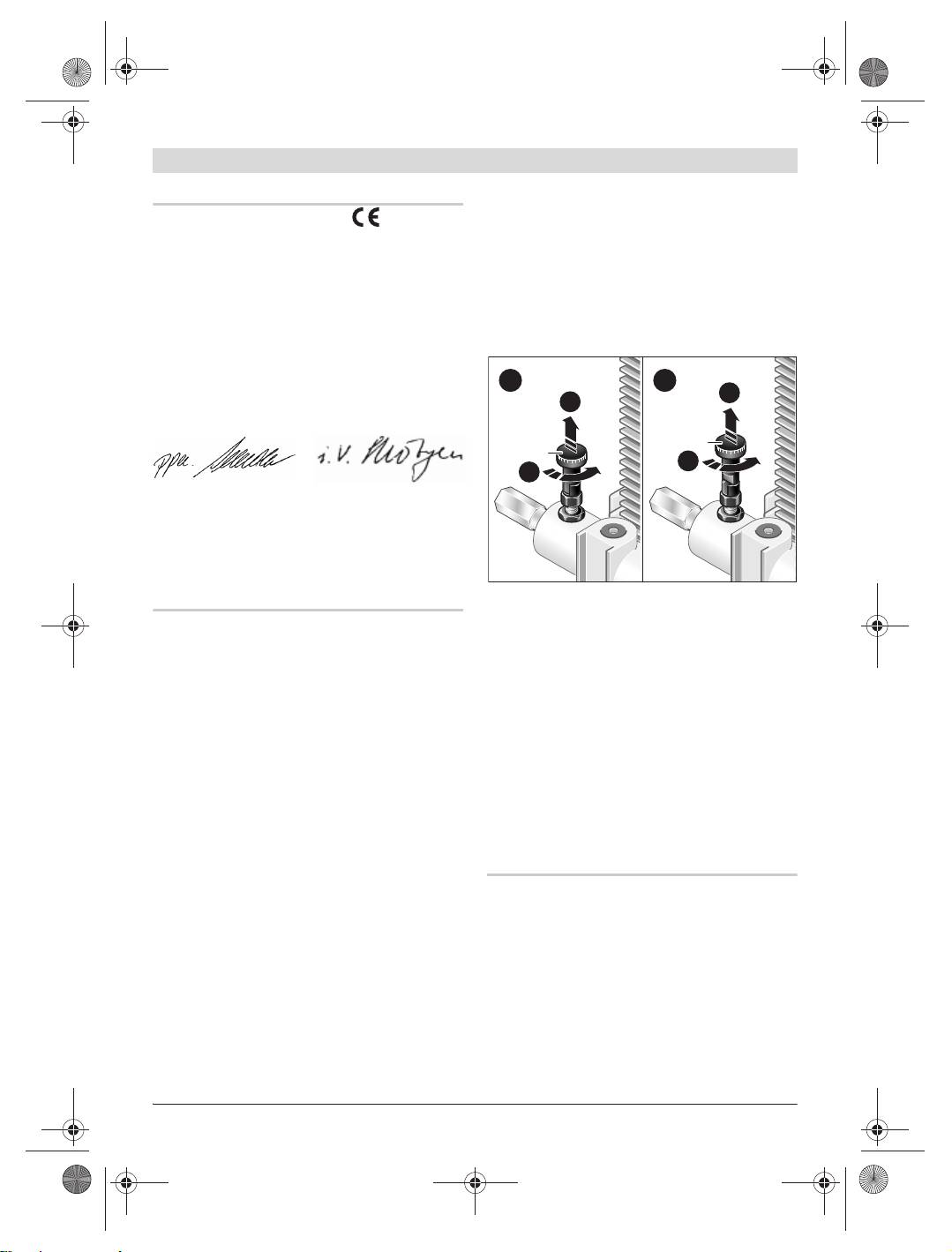
Geräteaufnahme nachstellen (siehe Bild H)
(siehe Bild G)
Um gute Bohrergebnisse zu erzielen, muss das
Lösen Sie die Knebelgriffe 6 und 7 am Bohrstän-
Spiel zwischen Geräteaufnahme 8 und Bohrsäu-
der. Achten Sie darauf, dass die Vorschubkurbel
le 2 so gering wie möglich sein.
17 durch die Vorschubarretierung 3 blockiert ist
(siehe „Vorschubkurbel“).
Lösen Sie zum Nachstellen die vier Innensechs-
Setzen Sie das Elektrowerkzeug von oben bis
kantschrauben 27. Ziehen Sie die Gleitelemente
zum Anschlag in die Geräteaufnahme 8 des
26 mit leichtem Druck durch Drehen der beiden
Bohrständers ein. Ziehen Sie die Knebelgriffe 6
Stellschrauben 28 an die Bohrsäule. Achten Sie
und 7 wieder fest. Beim Einsetzen der
darauf, dass die Geräteaufnahme parallel zur
GDB 1600 WE/DE wird der obere Knebelgriff 6
Bohrsäule ausgerichtet ist.
nicht benötigt.
Wenn das Gleitverhalten ausreichend ist, fixie-
Legen Sie den Wasserschlauch und das Netzka-
ren Sie die Stellschrauben 28 durch Anziehen
bel des Elektrowerkzeuges in die Halterungen
der Innensechskantschrauben 27.
an der Geräteaufnahme des Bohrständers ein.
Gehen Sie beim Entnehmen des Elektrowerk-
zeuges aus dem Bohrständer in umgekehrter
Reihenfolge vor.
1 609 929 W61 | (9.6.10) Bosch Power Tools
OBJ_BUCH-117-003.book Page 11 Wednesday, June 9, 2010 11:31 AM
Deutsch | 11
Sollte der Bohrständer trotz sorgfältiger Her-
Deutschland
stellungs- und Prüfverfahren einmal ausfallen,
Robert Bosch GmbH
ist die Reparatur von einer autorisierten Kun-
Servicezentrum Elektrowerkzeuge
dendienststelle für Bosch-Elektrowerkzeuge
Zur Luhne 2
ausführen zu lassen.
37589 Kalefeld – Willershausen
Geben Sie bei allen Rückfragen und Ersatzteilbe-
Tel. Kundendienst: +49 (1805) 70 74 10*
stellungen bitte unbedingt die 10-stellige Sach-
Fax: +49 (1805) 70 74 11*
nummer laut Typenschild des Bohrständers an.
(*Festnetzpreis 14 ct/min, höchstens 42 ct/min
aus Mobilfunknetzen)
Zubehör
E-Mail:
Servicezentrum.Elektrowerkzeuge@de.bosch.com
Transporträder. . . . . . . . . . . . . . 2 609 390 309
Tel. Kundenberatung: +49 (1803) 33 57 99
Befestigungsset:
(Festnetzpreis 9 ct/min, höchstens 42 ct/min
– für Beton. . . . . . . . . . . . . . . . 2 607 000 744
aus Mobilfunknetzen)
– für Mauerwerk . . . . . . . . . . . 2 607 000 745
Fax: +49 (711) 7 58 19 30
E-Mail: kundenberatung.ew@de.bosch.com
Schnellspannsäule . . . . . . . . . . . 2 608 598 111
Österreich
Verwendung mit GDB 2500 WE:
Tel.: +43 (01) 7 97 22 20 10
– Wasserfangring . . . . . . . . . . . 2 609 390 389
Fax: +43 (01) 7 97 22 20 11
– Dichtungsdeckel für
E-Mail: service.elektrowerkzeuge@at.bosch.com
Wasserfangring . . . . . . . . . . . 2 609 390 391
Verwendung mit GDB 1600 WE:
Schweiz
– Wasserfangring . . . . . . . . . . . 2 609 390 310
Tel.: +41 (044) 8 47 15 11
– Dichtungsdeckel für
Fax: +41 (044) 8 47 15 51
Wasserfangring . . . . . . . . . . . 2 609 390 311
Luxemburg
Tel.: +32 (070) 22 55 65
Kundendienst und Kundenberatung
Fax: +32 (070) 22 55 75
Der Kundendienst beantwortet Ihre Fragen zu
E-Mail: outillage.gereedschap@be.bosch.com
Reparatur und Wartung Ihres Produkts sowie zu
Weitere Informationen zum Diamantbohren fin-
Ersatzteilen. Explosionszeichnungen und Infor-
den Sie unter www.bosch-diamond.com.
mationen zu Ersatzteilen finden Sie auch unter:
www.bosch-pt.com
Das Bosch-Kundenberater-Team hilft Ihnen gerne
Entsorgung
bei Fragen zu Kauf, Anwendung und Einstellung
Bohrständer, Zubehör und Verpackungen sollen
von Produkten und Zubehören.
einer umweltgerechten Wiederverwertung zuge-
www.powertool-portal.de, das Internetportal
führt werden.
für Handwerker und Heimwerker.
www.ewbc.de, der Informations-Pool für Hand-
werk und Ausbildung.
Änderungen vorbehalten.
Bosch Power Tools 1 609 929 W61 | (9.6.10)
OBJ_BUCH-117-003.book Page 12 Wednesday, June 9, 2010 11:31 AM
12 | English
en
Safety Notes
f Store idle drill stands out of the reach of
children and do not allow persons unfamil-
WARNING
Read all safety warnings and in-
iar with the device or these instructions to
structions that were provided
operate the device. Drill stands are danger-
with the drill stand or the drill. Failure to follow
ous in the hands of untrained users.
the safety warnings and the instructions may re-
f Have your drill stand serviced/repaired on-
sult in electric shock, fire and/or serious injury.
ly by a qualified repair person using original
Save all safety warnings and instructions for
replacement parts. This will ensure that the
future reference.
safety of the device is maintained.
f Disconnect the plug from the power source
f Hold the drill stand by the insulated grip-
before making any adjustments or changing
ping surfaces when performing operations
accessories. Starting drills accidentally is
where the application tool could contact
the cause of some accidents.
hidden wiring or its own power cord. Con-
f Assemble the drill stand properly before
tact with a “live” wire will also make exposed
mounting the drill. The correct assembly is
metal parts of the drill stand “live” and shock
important in order to ensure proper function.
the operator.
f Before using, fasten the drill securely to the
f The safety and operating instructions for
drill stand. An unsecured drill in the drill
the drill and the accessories being used are
stand can lead to loss of control.
strictly to be observed!
f Fasten the drill stand on a firm and level
f Before any work on the drill stand or the
surface. When the drill stand can slip away
drill, during work breaks as well as when
or wobble, then the drill cannot be guided
not using for extending periods, secure the
uniformly and securely.
drill stand against unintentional moving by
f Do not overload the drill stand and do not
engaging the feed lock 3.
use it as a ladder or scaffold. Overloading or
standing on the drill stand can raise the drill
stand’s centre of gravity and cause it to tip
Functional Description
over.
Read all safety warnings and all
f Keep work area clean and well lit. Cluttered
instructions. Failure to follow the
or dark areas invite accidents.
warnings and instructions may re-
f Remove any adjusting key or wrench before
sult in electric shock, fire and/or
turning the power tool on. A wrench or a key
serious injury.
left attached to a rotating part of the power
While reading the operating instructions, unfold
tool may result in personal injury.
the fold-out page with the illustration of the drill
f Avoid abnormal body posture. Provide for a
stand and leave it open.
secure stance and keep your balance at all
times. In this manner, you can control the
Intended Use
power tool better in unexpected situations.
The drill stand for diamond drills is intended for
f Maintain the drill stand with care. Check for
mounting Bosch diamond drills. Other machines
misalignment or binding of moving parts,
may not be mounted.
breakage of parts and any other condition
The drill stand for diamond drills can be fas-
that may affect the function of the drill
tened to a wall or floor with anchor and quick-
stand. Have damaged parts repaired before
clamping spindle. In combination with the dia-
using the drill stand. Many accidents are
mond drills GDB 1600 WE or GDB 1600 DE, the
caused by poorly maintained devices.
drill stand can also be fastened overhead.
1 609 929 W61 | (9.6.10) Bosch Power Tools
OBJ_BUCH-117-003.book Page 13 Wednesday, June 9, 2010 11:31 AM
English | 13
Product Features
Technical Data
The numbering of the illustrated product fea-
Drill stand for diamond drills S 500 A
tures refers to the representation of the drill
Professional
stand on the graphics page.
Article number
0 601 190 025
1 Transport handle
Dimensions
2 Drilling column
– Height
mm
1010
3 Feed lock
–Width
mm
280
4 Spirit level for vertical alignment
–Depth
mm
465 (400*)
5 Spirit level for horizontal alignment
– Length of drilling
6 Upper locking handle on drill fixture
column
mm
1000
7 Lower locking handle on drill fixture
Drill stroke, max.
mm 500
8 Drill fixture
Drilling diameter (max.)
in concrete with
9 Rack
– GDB 1600 WE**
mm
102
10 Drill-hole centre indicator
– GDB 2500 WE***
mm
212
11 Levelling screw
Drilling diameter (max.)
12 Supporting bracket
in brickwork with
13 Knurled screw for supporting bracket
– GDB 1600 WE/DE**
mm
152
14 Hexagon screw for transport wheels
– GDB 2500 WE***
mm
152
15 Transport wheels
Weight according to
16 Lock pin for feed feed handle
EPTA-Procedure
01/2003
kg 12.5
17 Feed handle
* with supporting angles mounted to the rear
18 Handle (insulated gripping surface)
** with suction head
19 Angle scale
*** also possible with water collection ring (accessory)
20 Lock button for drill-angle adjustment
Please observe the article number on the type plate of
21 Upper locking handle for drill-angle adjust-
your drill stand. The trade names of individual drill
ment
stands may vary.
22 Lower locking handle for drill-angle adjust-
ment
Declaration of Conformity
23 Brickwork anchor*
We declare under our sole responsibility, that
24 Quick-clamping spindle*
the product described under “Technical data” is
25 Wing nut*
in conformity with the provisions of the direc-
26 Sliding elements
tive 2006/42/EC.
27 Allen screws of the drill fixture
Technical file at:
Robert Bosch GmbH, PT/ESC,
28 Adjusting screws of the drill fixture
D-70745 Leinfelden-Echterdingen
*Accessories shown or described are not part of the
Dr. Egbert Schneider
Dr. Eckerhard Strötgen
standard delivery scope of the product. A complete
Senior Vice President
Head of Product
overview of accessories can be found in our acces-
Engineering
Certification
sories program.
Robert Bosch GmbH, Power Tools Division
D-70745 Leinfelden-Echterdingen
Leinfelden, 22.04.2010
Bosch Power Tools 1 609 929 W61 | (9.6.10)
OBJ_BUCH-117-003.book Page 14 Wednesday, June 9, 2010 11:31 AM
14 | English
Assembly
Transport Wheels
For transport of the drill stand, screw the trans-
port wheels 15 to the sides of the drill stand
Mounting the Drill Stand
with the hexagon screws 14.
Supporting Angles
The supporting angles 12 can be mounted in
Fastening the Drill Stand
two positions:
Note: Fasten the drill stand free from play to
– The basic position (see Fig. A) is necessary
prevent jamming of the core bit and the tearing
when the GDB 2500 WE is installed into the
out of segments.
drill stand and the drill stand is not securely
mounted via anchor or quick-clamping
Depending on the type and surface quality, fas-
column.
ten the drill stand with anchor or quick-clamp-
– The space-saving position (see Fig. B) is only
ing column at the planned drill hole.
possible when using the GDB 1600 WE/DE
Positioning the Drill Stand before Fastening
or when the drill stand is securely fastened
to the wall. Assembly of the water collection
ring (accessory) for the GDB 2500 WE is not
possible in this position.
To switch between both positions, loosen the
knurled screws 13, adjust the supporting angles
12 to the required position and tighten them
again with the knurled screws.
Feed Handle
1010
Press the lock pin 16 on the feed handle and
keep it pressed. Slide the feed handle 17 to the
stop left or right of the drill fixture 8 as required.
GDB 2500 WE GDB 1600 WE/DE
Release the lock pin 16 and check the feed han-
Fold out the drill-hole centre indicator 10. When
dle for tight seating.
working with the GDB 2500 WE, bring the tip of
the drill-hole centre indicator into alignment
1
2
with the marked centre of the intended bore
A
A
hole. When working with the GDB 1600 WE/DE,
the inner edge of the drill-hole centre indicator
3
10 is the reference point.
3
B
For offset drilling, move the drill stand away
B
from the bore hole centre by the value m:
Drilling angle m
0° 0 mm
m*
m**
15° 30 mm
Afterwards, block the feed: Pull the feed lock 3
upward (A), turn it (B) and allow it to engage in
30° 80 mm
position c. If required, lightly rotate the feed
handle 17 until the lock can be heard to engage.
45° 160 mm
Release the feed only for drilling: Pull the feed
m*: GDB 2500 WE
lock 3 upward (A), turn it (B) and allow it to en-
m**: GDB 1600 WE/DE
gage in position d.
1 609 929 W61 | (9.6.10) Bosch Power Tools
OBJ_BUCH-117-003.book Page 15 Wednesday, June 9, 2010 11:31 AM
English | 15
Fasten the drill stand with anchor or quick-
Levelling
clamping column. Then fold in the drill-hole cen-
Screw the levelling screws 11 in or out individu-
tre indicator 10.
ally, until the spirit level 4 (for vertical assembly)
or the spirit level 5 (for horizontal assembly) is
Fastening with Anchor (see figure C)
precisely aligned.
For fastening of the drill stand to brickwork or
Now, firmly fasten the drill stand with anchor at-
concrete with anchor (accessory), drill a sepa-
tachment or with the quick-clamping column.
rate anchor hole.
Clearance from anchor hole–centre of the in-
tended bore hole
Operation
optimal possible
f After each adjustment on the drill stand,
GDB 2500 WE 330 mm 310–380 mm
firmly retighten all screws and locking han-
GDB 1600 WE/DE 270 mm 250–320 mm
dles and allow the locks to engage again.
For offset bore drilling, increase the distance
Drilling-angle Adjustment (see figure F)
between the anchor hole and the centre of the
intended bore hole by the value m (see “Posi-
Loosen the upper 21 and the lower locking han-
tioning the Drill Stand before Fastening”).
dle 22 for drill-angle adjustment.
The following dimensions apply for the anchor
Pull the lock button for drill-angle adjustment
hole:
20. Adjust the drill stand to one of the four pos-
sible drilling angles (0°, 15°, 30° or 45°) and al-
Diameter Depth
low the lock button to engage into the corre-
Brickwork 20 mm 85 mm
sponding hole in the drilling column.
Concrete 15 mm 50 mm
Tighten both locking handles 21 and 22 again.
Insert a concrete hammer-drive anchor or a
f The drill stand may not be used until both
brickwork anchor 23. Screw the quick-clamping
locking handles of the angle adjustment
spindle 24 into the anchor.
have been tightened again.
Position the drill stand, attach a washer, and
then screw together with the wing nut 25. After
Mounting the Diamond Drill
levelling (see “Levelling”), tighten the wing nut
(see figure G)
using an open-end spanner, size 27 mm.
Loosen the locking handles 6 and 7 on the drill
stand. Pay attention that the feed handle 17 is
Fastening with a Quick-clamping Column
blocked by the feed lock 3 (see “Feed Handle”).
(see figure D and E)
Insert the power tool from above into the drill
With use of a Bosch quick-clamping column (ac-
fixture 8 down to the stop. Retighten the locking
cessory), the drill stand can be fastened be-
handles 6 and 7 again. When mounting the
tween ceiling and floor or between two walls.
GDB 1600 WE/DE, the upper locking handle 6 is
The clamping range is between 1.7 m and 3 m.
not required.
Position one end of the quick-clamping column
Place the water hose and the mains cable of the
onto the base plate of the drill stand. The
power tool into the holders of the drill fixture on
mounting surface for the other end of the quick-
the drill stand.
clamping column against the wall must have suf-
Proceed in reverse order when removing the
ficient stability and be secure against slipping.
power tool from the drill stand.
For fastening the quick-clamping column, read
and observe its operating instructions.
Bosch Power Tools 1 609 929 W61 | (9.6.10)
OBJ_BUCH-117-003.book Page 16 Wednesday, June 9, 2010 11:31 AM
16 | English
If the drill stand should fail despite the care tak-
Water Extraction
en in manufacturing and testing procedures, re-
In order to collect the water coming out of the
pair should be carried out by an authorised af-
bore during wet-drilling, a water collection ring
ter-sales service centre for Bosch power tools.
and a multi-purpose vacuum cleaner are re-
In all correspondence and spare parts orders,
quired (both accessories).
please always include the 10-digit article
The choice of the water collection ring depends
number given on the nameplate of the drill
on the diamond drill (GDB 2500 WE or
stand.
GDB 1600 WE/DE) being used.
For assembly of the water collection ring, read
Accessories
and observe its operating instructions.
Transport Wheels. . . . . . . . . . . . 2 609 390 309
Fastening set:
Working Advice
– for concrete . . . . . . . . . . . . . 2 607 000 744
f For drilling, observe the operating instruc-
– for brickwork . . . . . . . . . . . . 2 607 000 745
tions of your diamond drill.
For drilling, loosen the lock pin for the feed han-
Quick-clamping column . . . . . . . 2 608 598 111
dle 17 (see “Feed Handle”).
Operation with GDB 2500 WE:
Lower the drill to the required drilling depth by
– Water collection ring. . . . . . . 2 609 390 389
turning the feed handle.
– Sealing lid for water
Then, turn the crank back until the core bit is
collection ring . . . . . . . . . . . . 2 609 390 391
completely visible.
Operation with GDB 1600 WE:
– Water collection ring. . . . . . . 2 609 390 310
– Sealing lid for water
Maintenance and Service
collection ring . . . . . . . . . . . . 2 609 390 311
Maintenance and Cleaning
After-sales Service and Customer
Always keep the rack 9 and the guide surfaces of
Assistance
the der drilling column 2 clean.
Our after-sales service responds to your ques-
tions concerning maintenance and repair of your
Readjusting the Drill Fixture (see figure H)
product as well as spare parts. Exploded views
In order to achieve good drilling results, the play
and information on spare parts can also be
between the drill fixture 8 and thr drilling col-
found under:
umn 2 must be as small as possible.
www.bosch-pt.com
For readjustment, loosen the four Allen screws
Our customer service representatives can an-
27. Tighten the sliding elements 26 with slight
swer your questions concerning possible appli-
pressure toward the drilling column by turning
cations and adjustment of products and acces-
the two adjustment screws 28. Pay attention
sories.
that the drill fixture is aligned parallel to the
drilling column.
When the sliding behaviour is sufficient, lock the
adjustment screws 28 by retightening the Allen
screws 27.
1 609 929 W61 | (9.6.10) Bosch Power Tools
OBJ_BUCH-117-003.book Page 17 Wednesday, June 9, 2010 11:31 AM
English | 17
Great Britain
KZN – BSC Service Centre
Robert Bosch Ltd. (B.S.C.)
Unit E, Almar Centre
P.O. Box 98
143 Crompton Street
Broadwater Park
Pinetown
North Orbital Road
Tel.: +27 (031) 7 01 21 20
Denham
Fax: +27 (031) 7 01 24 46
Uxbridge
E-Mail: bsc.dur@za.bosch.com
UB 9 5HJ
Western Cape – BSC Service Centre
Tel. Service: +44 (0844) 736 0109
Democracy Way, Prosperity Park
Fax: +44 (0844) 736 0146
Milnerton
E-Mail: boschservicecentre@bosch.com
Tel.: +27 (021) 5 51 25 77
Fax: +27 (021) 5 51 32 23
Ireland
E-Mail: bsc@zsd.co.za
Origo Ltd.
Bosch Headquarters
Unit 23 Magna Drive
Midrand, Gauteng
Magna Business Park
Tel.: +27 (011) 6 51 96 00
City West
Fax: +27 (011) 6 51 98 80
Dublin 24
E-Mail: rbsa-hq.pts@za.bosch.com
Tel. Service: +353 (01) 4 66 67 00
Fax: +353 (01) 4 66 68 88
People’s Republic of China
Australia, New Zealand and Pacific Islands
Website: www.bosch-pt.com.cn
Robert Bosch Australia Pty. Ltd.
China Mainland
Power Tools
Bosch Power Tools (China) Co., Ltd.
Locked Bag 66
567, Bin Kang Road
Clayton South VIC 3169
Bin Jiang District 310052
Customer Contact Center
Hangzhou, P.R.China
Inside Australia:
Service Hotline: 800 8 20 84 84
Phone: +61 (01300) 307 044
Tel.: +86 (571) 87 77 43 38
Fax: +61 (01300) 307 045
Fax: +86 (571) 87 77 45 02
Inside New Zealand:
HK and Macau Special Administrative Regions
Phone: +64 (0800) 543 353
Robert Bosch Hong Kong Co. Ltd.
Fax: +64 (0800) 428 570
21st Floor, 625 King’s Road
Outside AU and NZ:
North Point, Hong Kong
Phone: +61 (03) 9541 5555
Customer Service Hotline: +852 (21) 02 02 35
www.bosch.com.au
Fax: +852 (25) 90 97 62
E-Mail: info@hk.bosch.com
Republic of South Africa
www.bosch-pt.com.cn
Customer service
Hotline: +27 (011) 6 51 96 00
Indonesia
Gauteng – BSC Service Centre
PT. Multi Tehaka
35 Roper Street, New Centre
Kawasan Industri Pulogadung
Johannesburg
Jalan Rawa Gelam III No. 2
Tel.: +27 (011) 4 93 93 75
Jakarta 13930
Fax: +27 (011) 4 93 01 26
Indonesia
E-Mail: bsctools@icon.co.za
Tel.: +62 (21) 46 83 25 22
Fax: +62 (21) 46 82 86 45/68 23
E-Mail: sales@multitehaka.co.id
www.multitehaka.co.id
Bosch Power Tools 1 609 929 W61 | (9.6.10)
OBJ_BUCH-117-003.book Page 18 Wednesday, June 9, 2010 11:31 AM
18 | English
Philippines
Singapore
Robert Bosch, Inc.
Robert Bosch (SEA) Pte. Ltd.
28th Floor Fort Legend Towers,
11 Bishan Street 21
3rd Avenue corner 31st Street,
Singapore 573943
Fort Bonifacio Global City,
Tel.: +65 6571 2772
1634 Taguig City, Philippines
Fax: +65 6350 5315
Tel.: +63 (2) 870 3871
leongheng.leow@sg.bosch.com
Fax: +63 (2) 870 3870
Toll-Free: 1800 333 8333
matheus.contiero@ph.bosch.com
www.bosch-pt.com.sg
www.bosch-pt.com.ph
Vietnam
Bosch Service Center:
9725-27 Kamagong Street
Robert Bosch Vietnam Co. Ltd
San Antonio Village
10/F, 194 Golden Building
Makati City, Philippines
473 Dien Bien Phu Street
Tel.: +63 (2) 899 9091
Ward 25, Binh Thanh District
Fax: +63 (2) 897 6432
84 Ho Chi Minh City
rosalie.dagdagan@ph.bosch.com
Vietnam
Tel.: +84 (8) 6258 3690 ext. 413
Malaysia
Fax: +84 (8) 6258 3692
Robert Bosch (S.E.A.) Pte. Ltd.
hieu.lagia@vn.bosch.com
No. 8A, Jalan 13/6
www.bosch-pt.com
G.P.O. Box 10818
Further informations on diamond drilling can be
46200 Petaling Jaya
found under www.bosch-diamond.com.
Selangor, Malaysia
Tel.: +60 (3) 7966 3194
Disposal
Fax: +60 (3) 7958 3838
cheehoe.on@my.bosch.com
The drill stand, accessories and packaging
Toll-Free: 1800 880 188
should be sorted for environmental-friendly
www.bosch-pt.com.my
recycling.
Thailand
Subject to change without notice.
Robert Bosch Ltd.
Liberty Square Building
No. 287, 11 Floor
Silom Road, Bangrak
Bangkok 10500
Tel.: +66 (2) 6 31 18 79 – 18 88 (10 lines)
Fax: +66 (2) 2 38 47 83
Robert Bosch Ltd., P. O. Box 2054
Bangkok 10501, Thailand
Bosch Service – Training Centre
2869-2869/1 Soi Ban Kluay
Rama IV Road (near old Paknam Railway)
Prakanong District
10110 Bangkok
Thailand
Tel.: +66 (2) 6 71 78 00 – 4
Fax: +66 (2) 2 49 42 96
Fax: +66 (2) 2 49 52 99
1 609 929 W61 | (9.6.10) Bosch Power Tools
OBJ_BUCH-117-003.book Page 19 Wednesday, June 9, 2010 11:31 AM
Français | 19
fr
Avertissements de sécurité
f Eviter les positions anormales. Veiller à tou-
jours garder une position stable et à être en
AVERTISSEMENT
Lire la totalité des con-
équilibre. Ceci vous permet de mieux contrô-
signes de sécurité et
ler l’outil électroportatif dans des situations
des instructions fournies avec le support de
inattendues.
perçage et la perceuse. Le non-respect des con-
f Prendre soin du support de perçage. S’as-
signes de sécurité et des instructions peut en-
surer que les parties mobiles fonctionnent
traîner une décharge électrique, un incendie
correctement, qu’elles ne sont pas coin-
et/ou de graves blessures.
cées, et contrôler si des pièces sont cas-
Conserver les consignes de sécurité et instruc-
sées ou endommagées de sorte à entraver
tions pour une consultation ultérieure.
le bon fonctionnement du support de perça-
f Retirer la fiche de la prise de courant avant
ge. Faire réparer les parties endommagées
d’effectuer des réglages sur l’appareil ou de
avant d’utiliser le support de perçage. De
changer les accessoires. Une mise en route
nombreux accidents sont dus à des appareils
involontaire est une cause courante d’acci-
mal entretenus.
dent.
f Garder les supports de perçage non utilisés
f Montez d’abord correctement le support de
hors de portée des enfants. Ne pas permet-
perçage avant de commencer le montage de
tre l’utilisation de l’appareil à des person-
la perceuse. Un assemblage correct est es-
nes qui ne se sont pas familiarisées avec ce-
sentiel pour le bon fonctionnement de l’en-
lui-ci ou qui n’ont pas lu ces instructions.
semble.
Les appareils sont dangereux lorsqu’ils sont
f Fixez correctement la perceuse au support
utilisés par des personnes non initiées.
de perçage avant de commencer à l’utiliser.
f Ne faire réparer le support de perçage que
Si la perceuse se met à glisser dans le sup-
par un personnel qualifié et seulement avec
port, vous risquez de perdre le contrôle de la
des pièces de rechange d’origine. Ceci per-
perceuse.
met d’assurer la sécurité de l’appareil.
f Fixer le support de perçage sur une surface
f Tenir le support de perçage par les surfaces
stable et plane. Si le support de perçage
de préhension isolantes, pendant les opéra-
peut glisser ou vaciller, la perceuse ne peut
tions au cours desquelles l’accessoire cou-
pas être guidée de manière régulière et sûre.
pant peut être en contact avec des conduc-
f Ne pas surcharger le support de perçage et
teurs cachés ou avec son propre câble.
Le
ne pas l’utiliser en tant qu’échelle ou écha-
contact de l’accessoire coupant avec un fil
faudage. Le fait de surcharger le support de
« sous tension » peut également mettre
perçage ou de se placer dessus peut avoir
« sous tension » les parties métalliques ex-
pour conséquence que le centre de gravité
posées du support de perçage et provoquer
du support de perçage se déplace vers le
un choc électrique sur l’opérateur.
haut et qu’il se renverse.
f Respecter scrupuleusement les instruc-
f Conserver la zone de travail propre et bien
tions de sécurité ainsi que les indications
éclairée. Les zones en désordre ou sombres
de travail de la perceuse montée et des ac-
sont propices aux accidents.
cessoires utilisés !
f Enlever tout outil de réglage ou toute clé
f Avant tout travail effectué sur le support de
avant de mettre l’appareil en fonctionne-
perçage ou la perceuse, lors des pauses de
ment. Une clé ou un outil se trouvant sur une
travail ainsi qu’en cas de non-utilisation,
partie en rotation peut causer des blessures.
bloquer le support de perçage en ver-
rouillant le blocage d’avance 3 pour éviter
ainsi un mouvement non-intentionné.
Bosch Power Tools 1 609 929 W61 | (9.6.10)
OBJ_BUCH-117-003.book Page 20 Wednesday, June 9, 2010 11:31 AM
20 | Français
Description du fonctionnement
Eléments de l’appareil
Il est impératif de lire toutes les
La numérotation des éléments de l’appareil se
consignes de sécurité et toutes les
réfère à la représentation du support de perça-
instructions. Le non-respect des
ge sur la page graphique.
avertissements et instructions indi-
1 Poignée de transport
qués ci-après peut conduire à une
électrocution, un incendie et/ou de
2 Colonne
graves blessures.
3 Blocage d’avance
Dépliez le volet sur lequel le support de perçage
4 Bulle d’air pour orientation verticale
est représenté de manière graphique. Laissez le
5 Bulle d’air pour orientation horizontale
volet déplié pendant la lecture de la présente
6 Manette supérieure sur la fixation
notice d’utilisation.
7 Manette inférieure se trouvant sur la fixation
8 Fixation
Utilisation conforme
9 Crémaillère
Le support de perçage diamanté est conçu pour
10 Marquage central du trou de perçage
y monter des perceuses diamantées Bosch. Ne
pas monter d’autres appareils.
11 Vis de nivellement
Il est possible de monter le support de perçage
12 Angle-support
diamanté sur le sol ou au mur à l’aide de che-
13 Vis moletée pour angle-support
villes ou d’une colonne à serrage rapide. En
14 Vis à six pans creux pour roues de transport
combinaison avec les perceuses diamantées
15 Roues de transport
GDB 1600 WE ou GDB 1600 DE, il est possible
de monter le support de perçage au-dessus de
16 Tige de blocage de la manivelle d’avance
la hauteur de la tête.
17 Manivelle d’avance
18 Poignée (surface de préhension isolante)
19 Graduation angulaire
20 Bouton de blocage de la modification de
l’angle de perçage
21 Manette supérieure pour la modification de
l’angle de perçage
22 Manette inférieure pour la modification de
l’angle de perçage
23 Cheville à murage*
24 Broche à serrage rapide*
25 Ecrou papillon*
26 Eléments de glissage
27 Vis à six pans de la fixation
28 Vis de réglage de la fixation
*Les accessoires décrits ou illustrés ne sont pas tous
compris dans la fourniture. Vous trouverez les acces-
soires complets dans notre programme d’accessoires.
1 609 929 W61 | (9.6.10) Bosch Power Tools
