Bosch GBH 4-32 DFR Professional: инструкция
Раздел: Инструмент, электроинструмент, силовая техника
Тип: Перфоратор
Характеристики, спецификации
Инструкция к Перфоратору Bosch GBH 4-32 DFR Professional
Robert Bosch GmbH
Power Tools Division
70745 Leinfelden-Echterdingen
Germany
GBH 4-32 DFR Professional
www.bosch-pt.com
1 609 92A 044 (2013.01) PS / 178 UNI
de Originalbetriebsanleitung
el Πρωτότυπο οδηγιών χρήσης
sr Originalno uputstvo za rad
en Original instructions
tr Orijinal işletme talimatı
sl Izvirna navodila
fr Notice originale
pl Instrukcja oryginalna
hr Originalne upute za rad
es Manual original
cs Původní návod k používání
et Algupärane kasutusjuhend
pt Manual original
sk Pôvodný návod na použitie
lv Instrukcijas oriģinālvalodā
it Istruzioni originali
hu Eredeti használati utasítás
lt Originali instrukcija
nl Oorspronkelijke gebruiksaanwij-
ru Оригинальное руководство по эк-
ar
zing
сплуатации
fa
da Original brugsanvisning
uk Оригінальна інструкція з
sv Bruksanvisning i original
експлуатації
no Original driftsinstruks
ro Instrucţiuni originale
fi Alkuperäiset ohjeet
bg Оригинална инструкция
ςТЎϩХʉ ЌТϾϦφЍʉ ʌμВТЎϺυ
ΖЎϩʉ ˒μВЖЙʉʓ ИͳϞφЁʑ
OBJ_BUCH-337-006.book Page 1 Thursday, January 10, 2013 1:20 PM
OBJ_BUCH-337-006.book Page 2 Thursday, January 10, 2013 1:23 PM
2 |
Deutsch. . . . . . . . . . . . . . . . . . . . . . . . . . . . . . . . . . . . . . . . . Seite 6
English . . . . . . . . . . . . . . . . . . . . . . . . . . . . . . . . . . . . . . . . . . Page 12
Français . . . . . . . . . . . . . . . . . . . . . . . . . . . . . . . . . . . . . . . . . Page 17
Español. . . . . . . . . . . . . . . . . . . . . . . . . . . . . . . . . . . . . . . . Página 24
Português . . . . . . . . . . . . . . . . . . . . . . . . . . . . . . . . . . . . . . Página 30
Italiano . . . . . . . . . . . . . . . . . . . . . . . . . . . . . . . . . . . . . . . . Pagina 36
Nederlands. . . . . . . . . . . . . . . . . . . . . . . . . . . . . . . . . . . . . Pagina 42
Dansk . . . . . . . . . . . . . . . . . . . . . . . . . . . . . . . . . . . . . . . . . . . Side 48
Svenska . . . . . . . . . . . . . . . . . . . . . . . . . . . . . . . . . . . . . . . . . Sida 53
Norsk. . . . . . . . . . . . . . . . . . . . . . . . . . . . . . . . . . . . . . . . . . . . Side 58
Suomi . . . . . . . . . . . . . . . . . . . . . . . . . . . . . . . . . . . . . . . . . . . Sivu 63
Ελληνικά . . . . . . . . . . . . . . . . . . . . . . . . . . . . . . . . . . . . . . . Σελίδα 69
Türkçe. . . . . . . . . . . . . . . . . . . . . . . . . . . . . . . . . . . . . . . . . . Sayfa 75
Polski . . . . . . . . . . . . . . . . . . . . . . . . . . . . . . . . . . . . . . . . . Strona 81
Česky . . . . . . . . . . . . . . . . . . . . . . . . . . . . . . . . . . . . . . . . . Strana 87
Slovensky . . . . . . . . . . . . . . . . . . . . . . . . . . . . . . . . . . . . . . Strana 92
Magyar . . . . . . . . . . . . . . . . . . . . . . . . . . . . . . . . . . . . . . . . . Oldal 98
Русский . . . . . . . . . . . . . . . . . . . . . . . . . . . . . . . . . . . . Страница 105
Українська . . . . . . . . . . . . . . . . . . . . . . . . . . . . . . . . . . . Сторінка 111
Română. . . . . . . . . . . . . . . . . . . . . . . . . . . . . . . . . . . . . . . . Pagina 117
Български . . . . . . . . . . . . . . . . . . . . . . . . . . . . . . . . . . Страница 123
Srpski . . . . . . . . . . . . . . . . . . . . . . . . . . . . . . . . . . . . . . . . . Strana 130
Slovensko . . . . . . . . . . . . . . . . . . . . . . . . . . . . . . . . . . . . . . . Stran 135
Hrvatski. . . . . . . . . . . . . . . . . . . . . . . . . . . . . . . . . . . . . . . Stranica 141
Eesti . . . . . . . . . . . . . . . . . . . . . . . . . . . . . . . . . . . . . . . . Lehekülg 146
Latviešu . . . . . . . . . . . . . . . . . . . . . . . . . . . . . . . . . . . . . . Lappuse 151
Lietuviškai. . . . . . . . . . . . . . . . . . . . . . . . . . . . . . . . . . . . . Puslapis 157
. . . . . . . . . . . . . . . . . . . . . . . . . . . . . . 169
. . . . . . . . . . . . . . . . . . . . . . . . . . . . . . 176
1 609 92A 044 | (10.1.13) Bosch Power Tools
OBJ_BUCH-337-006.book Page 3 Thursday, January 10, 2013 1:23 PM
3 |
6
5
7
1
4
3
2
11 9810
12
10
GBH 4-32 DFR
1 609 92A 044 | (10.1.13) Bosch Power Tools
OBJ_BUCH-337-006.book Page 4 Thursday, January 10, 2013 1:23 PM
4 |
A
x
11 910
B
4
1
C
1 609 92A 044 | (10.1.13) Bosch Power Tools
OBJ_BUCH-337-006.book Page 5 Thursday, January 10, 2013 1:23 PM
5 |
D
3
E
13
14 15
GRIP, ZU
RELEASE, AUF
9
GF
X
16
17 18 19 20 21
1 609 92A 044 | (10.1.13) Bosch Power Tools
OBJ_BUCH-337-006.book Page 6 Thursday, January 10, 2013 1:23 PM
6 | Deutsch
Wenn der Betrieb des Elektrowerkzeuges in feuchter
Deutsch
Umgebung nicht vermeidbar ist, verwenden Sie einen
Fehlerstromschutzschalter. Der Einsatz eines Fehler-
stromschutzschalters vermindert das Risiko eines elektri-
Sicherheitshinweise
schen Schlages.
Allgemeine Sicherheitshinweise für Elektrowerk-
Sicherheit von Personen
zeuge
Seien Sie aufmerksam, achten Sie darauf, was Sie tun,
und gehen Sie mit Vernunft an die Arbeit mit einem
Lesen Sie alle Sicherheitshinweise und
WARNUNG
Elektrowerkzeug. Benutzen Sie kein Elektrowerkzeug,
Anweisungen. Versäumnisse bei der Ein-
wenn Sie müde sind oder unter dem Einfluss von Dro-
haltung der Sicherheitshinweise und Anweisungen können
gen, Alkohol oder Medikamenten stehen. Ein Moment
elektrischen Schlag, Brand und/oder schwere Verletzungen
der Unachtsamkeit beim Gebrauch des Elektrowerkzeuges
verursachen.
kann zu ernsthaften Verletzungen führen.
Bewahren Sie alle Sicherheitshinweise und Anweisungen
Tragen Sie persönliche Schutzausrüstung und immer
für die Zukunft auf.
eine Schutzbrille. Das Tragen persönlicher Schutzausrüs-
Der in den Sicherheitshinweisen verwendete Begriff „Elektro-
tung, wie Staubmaske, rutschfeste Sicherheitsschuhe,
werkzeug“ bezieht sich auf netzbetriebene Elektrowerkzeuge
Schutzhelm oder Gehörschutz, je nach Art und Einsatz des
(mit Netzkabel) und auf akkubetriebene Elektrowerkzeuge
Elektrowerkzeuges, verringert das Risiko von Verletzun-
(ohne Netzkabel).
gen.
Arbeitsplatzsicherheit
Vermeiden Sie eine unbeabsichtigte Inbetriebnahme.
Halten Sie Ihren Arbeitsbereich sauber und gut be-
Vergewissern Sie sich, dass das Elektrowerkzeug aus-
leuchtet. Unordnung oder unbeleuchtete Arbeitsbereiche
geschaltet ist, bevor Sie es an die Stromversorgung
können zu Unfällen führen.
und/oder den Akku anschließen, es aufnehmen oder
Arbeiten Sie mit dem Elektrowerkzeug nicht in explosi-
tragen. Wenn Sie beim Tragen des Elektrowerkzeuges den
onsgefährdeter Umgebung, in der sich brennbare Flüs-
Finger am Schalter haben oder das Gerät eingeschaltet an
sigkeiten, Gase oder Stäube befinden. Elektrowerkzeu-
die Stromversorgung anschließen, kann dies zu Unfällen
ge erzeugen Funken, die den Staub oder die Dämpfe
führen.
entzünden können.
Entfernen Sie Einstellwerkzeuge oder Schrauben-
Halten Sie Kinder und andere Personen während der
schlüssel, bevor Sie das Elektrowerkzeug einschalten.
Benutzung des Elektrowerkzeugs fern. Bei Ablenkung
Ein Werkzeug oder Schlüssel, der sich in einem drehenden
können Sie die Kontrolle über das Gerät verlieren.
Geräteteil befindet, kann zu Verletzungen führen.
Vermeiden Sie eine abnormale Körperhaltung. Sorgen
Elektrische Sicherheit
Sie für einen sicheren Stand und halten Sie jederzeit
Der Anschlussstecker des Elektrowerkzeuges muss in
das Gleichgewicht. Dadurch können Sie das Elektrowerk-
die Steckdose passen. Der Stecker darf in keiner Weise
zeug in unerwarteten Situationen besser kontrollieren.
verändert werden. Verwenden Sie keine Adapterste-
Tragen Sie geeignete Kleidung. Tragen Sie keine weite
cker gemeinsam mit schutzgeerdeten Elektrowerkzeu-
Kleidung oder Schmuck. Halten Sie Haare, Kleidung
gen. Unveränderte Stecker und passende Steckdosen ver-
und Handschuhe fern von sich bewegenden Teilen. Lo-
ringern das Risiko eines elektrischen Schlages.
ckere Kleidung, Schmuck oder lange Haare können von
Vermeiden Sie Körperkontakt mit geerdeten Oberflä-
sich bewegenden Teilen erfasst werden.
chen wie von Rohren, Heizungen, Herden und Kühl-
Wenn Staubabsaug- und -auffangeinrichtungen mon-
schränken. Es besteht ein erhöhtes Risiko durch elektri-
tiert werden können, vergewissern Sie sich, dass diese
schen Schlag, wenn Ihr Körper geerdet ist.
angeschlossen sind und richtig verwendet werden. Ver-
Halten Sie Elektrowerkzeuge von Regen oder Nässe
wendung einer Staubabsaugung kann Gefährdungen
fern. Das Eindringen von Wasser in ein Elektrowerkzeug
durch Staub verringern.
erhöht das Risiko eines elektrischen Schlages.
Verwendung und Behandlung des Elektrowerkzeuges
Zweckentfremden Sie das Kabel nicht, um das Elektro-
werkzeug zu tragen, aufzuhängen oder um den Stecker
Überlasten Sie das Gerät nicht. Verwenden Sie für Ihre
aus der Steckdose zu ziehen. Halten Sie das Kabel fern
Arbeit das dafür bestimmte Elektrowerkzeug. Mit dem
von Hitze, Öl, scharfen Kanten oder sich bewegenden
passenden Elektrowerkzeug arbeiten Sie besser und si-
Geräteteilen. Beschädigte oder verwickelte Kabel erhö-
cherer im angegebenen Leistungsbereich.
hen das Risiko eines elektrischen Schlages.
Benutzen Sie kein Elektrowerkzeug, dessen Schalter
Wenn Sie mit einem Elektrowerkzeug im Freien arbei-
defekt ist. Ein Elektrowerkzeug, das sich nicht mehr ein-
ten, verwenden Sie nur Verlängerungskabel, die auch
oder ausschalten lässt, ist gefährlich und muss repariert
für den Außenbereich geeignet sind. Die Anwendung ei-
werden.
nes für den Außenbereich geeigneten Verlängerungska-
Ziehen Sie den Stecker aus der Steckdose und/oder
bels verringert das Risiko eines elektrischen Schlages.
entfernen Sie den Akku, bevor Sie Geräteeinstellungen
vornehmen, Zubehörteile wechseln oder das Gerät
1 609 92A 044 | (10.1.13) Bosch Power Tools
OBJ_BUCH-337-006.book Page 7 Thursday, January 10, 2013 1:23 PM
Deutsch | 7
weglegen. Diese Vorsichtsmaßnahme verhindert den un-
Sichern Sie das Werkstück. Ein mit Spannvorrichtungen
beabsichtigten Start des Elektrowerkzeuges.
oder Schraubstock festgehaltenes Werkstück ist sicherer
Bewahren Sie unbenutzte Elektrowerkzeuge außer-
gehalten als mit Ihrer Hand.
halb der Reichweite von Kindern auf. Lassen Sie Perso-
Warten Sie, bis das Elektrowerkzeug zum Stillstand ge-
nen das Gerät nicht benutzen, die mit diesem nicht ver-
kommen ist, bevor Sie es ablegen. Das Einsatzwerkzeug
traut sind oder diese Anweisungen nicht gelesen
kann sich verhaken und zum Verlust der Kontrolle über das
haben. Elektrowerkzeuge sind gefährlich, wenn sie von
Elektrowerkzeug führen.
unerfahrenen Personen benutzt werden.
Pflegen Sie Elektrowerkzeuge mit Sorgfalt. Kontrollie-
Produkt- und Leistungsbeschreibung
ren Sie, ob bewegliche Teile einwandfrei funktionieren
und nicht klemmen, ob Teile gebrochen oder so be-
Lesen Sie alle Sicherheitshinweise und An-
schädigt sind, dass die Funktion des Elektrowerkzeu-
weisungen. Versäumnisse bei der Einhaltung
ges beeinträchtigt ist. Lassen Sie beschädigte Teile vor
der Sicherheitshinweise und Anweisungen
dem Einsatz des Gerätes reparieren. Viele Unfälle haben
können elektrischen Schlag, Brand und/oder
ihre Ursache in schlecht gewarteten Elektrowerkzeugen.
schwere Verletzungen verursachen.
Halten Sie Schneidwerkzeuge scharf und sauber. Sorg-
Bitte klappen Sie die Aufklappseite mit der Darstellung des
fältig gepflegte Schneidwerkzeuge mit scharfen Schneid-
Elektrowerkzeugs auf, und lassen Sie diese Seite aufgeklappt,
kanten verklemmen sich weniger und sind leichter zu füh-
während Sie die Betriebsanleitung lesen.
ren.
Bestimmungsgemäßer Gebrauch
Verwenden Sie Elektrowerkzeug, Zubehör, Einsatz-
Das Elektrowerkzeug ist bestimmt zum Hammerbohren in Be-
werkzeuge usw. entsprechend diesen Anweisungen.
ton, Ziegel und Gestein sowie für leichte Meißelarbeiten. Es
Berücksichtigen Sie dabei die Arbeitsbedingungen und
ist ebenso geeignet zum Bohren ohne Schlag in Holz, Metall,
die auszuführende Tätigkeit. Der Gebrauch von Elektro-
Keramik und Kunststoff. Elektrowerkzeuge mit elektronischer
werkzeugen für andere als die vorgesehenen Anwendun-
Regelung und Rechts-/Linkslauf sind auch geeignet zum
gen kann zu gefährlichen Situationen führen.
Schrauben.
Service
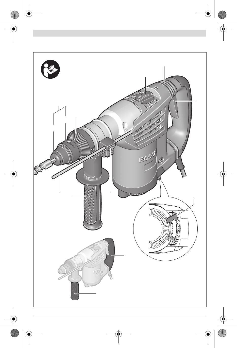
Abgebildete Komponenten
Lassen Sie Ihr Elektrowerkzeug nur von qualifiziertem
Fachpersonal und nur mit Original-Ersatzteilen repa-
Die Nummerierung der abgebildeten Komponenten bezieht
rieren. Damit wird sichergestellt, dass die Sicherheit des
sich auf die Darstellung des Elektrowerkzeuges auf der Grafik-
Elektrowerkzeuges erhalten bleibt.
seite.
1 Werkzeugaufnahme SDS-plus
Sicherheitshinweise für Hämmer
2 Staubschutzkappe
Tragen Sie Gehörschutz. Die Einwirkung von Lärm kann
3 Verriegelungshülse
Gehörverlust bewirken.
4 Verriegelungsring für Werkzeugaufnahme
Benutzen Sie Zusatzgriffe, wenn diese mit dem Elekt-
5 Schlag-/Drehstopp-Schalter
rowerkzeug mitgeliefert werden. Der Verlust der Kont-
rolle kann zu Verletzungen führen.
6 Vibrationsdämpfung
Halten Sie das Gerät an den isolierten Griffflächen,
7 Ein-/Ausschalter
wenn Sie Arbeiten ausführen, bei denen das Einsatz-
8 Drehrichtungsumschalter
werkzeug oder die Schraube verborgene Stromleitun-
9 Taste für Tiefenanschlageinstellung
gen oder das eigene Netzkabel treffen kann. Der Kon-
10 Zusatzgriff (isolierte Grifffläche)
takt mit einer spannungsführenden Leitung kann auch
11 Tiefenanschlag
metallene Geräteteile unter Spannung setzen und zu ei-
12 Handgriff (isolierte Grifffläche)
nem elektrischen Schlag führen.
13 Schnellspann-Wechselbohrfutter*
Verwenden Sie geeignete Suchgeräte, um verborgene
14 Vordere Hülse des Schnellspann-Wechselbohrfutters*
Versorgungsleitungen aufzuspüren, oder ziehen Sie
die örtliche Versorgungsgesellschaft hinzu. Kontakt mit
15 Haltering des Schnellspann-Wechselbohrfutters*
Elektroleitungen kann zu Feuer und elektrischem Schlag
16 Absaugöffnung Saugfix*
führen. Beschädigung einer Gasleitung kann zur Explosion
17 Klemmschraube Saugfix*
führen. Eindringen in eine Wasserleitung verursacht Sach-
18 Tiefenanschlag Saugfix*
beschädigung oder kann einen elektrischen Schlag verur-
19 Teleskoprohr Saugfix*
sachen.
20 Flügelschraube Saugfix*
Halten Sie das Elektrowerkzeug beim Arbeiten fest mit
21 Führungsrohr Saugfix*
beiden Händen und sorgen Sie für einen sicheren
*Abgebildetes oder beschriebenes Zubehör gehört nicht zum
Stand. Das Elektrowerkzeug wird mit zwei Händen siche-
Standard-Lieferumfang. Das vollständige Zubehör finden Sie in
rer geführt.
unserem Zubehörprogramm.
Bosch Power Tools 1 609 92A 044 | (10.1.13)
OBJ_BUCH-337-006.book Page 8 Thursday, January 10, 2013 1:23 PM
8 | Deutsch
Technische Daten
Legen Sie zusätzliche Sicherheitsmaßnahmen zum Schutz des
Bedieners vor der Wirkung von Schwingungen fest wie zum
Bohrhammer GBH 4-32 DFR
Beispiel: Wartung von Elektrowerkzeug und Einsatzwerkzeu-
Sachnummer
3 611 C32 0..
gen, Warmhalten der Hände, Organisation der Arbeitsabläufe.
3 611 C32 1..
Konformitätserklärung
Nennaufnahmeleistung
W900
-1
Wir erklären in alleiniger Verantwortung, dass das unter
Drehzahl
min
0–760
„Technische Daten“ beschriebene Produkt mit den folgenden
-1
Schlagzahl
min
0 –3600
Normen oder normativen Dokumenten übereinstimmt:
Einzelschlagstärke entspre-
EN 60745 gemäß den Bestimmungen der Richtlinien
chend EPTA-Procedure
2011/65/EU, 2004/108/EG, 2006/42/EG.
05/2009
J4,2
Technische Unterlagen (2006/42/EG) bei:
Meißelstellungen
12
Robert Bosch GmbH, PT/ETM9,
D-70745 Leinfelden-Echterdingen
Werkzeugaufnahme
SDS-plus
Dr. Egbert Schneider
Helmut Heinzelmann
Schmierung
Zentrale
Senior Vice President
Head of Product Certification
Dauerschmierung
Engineering
PT/ETM9
max. Bohr-Ø
– Beton (mit Wendelbohrer)
mm
32
– Mauerwerk (mit Hohlbohr-
krone)
mm
90
–Stahl
mm
13
Robert Bosch GmbH, Power Tools Division
D-70745 Leinfelden-Echterdingen
–Holz
mm
32
Leinfelden, 14.12.2012
Gewicht entsprechend
EPTA-Procedure 01/2003
kg 4,7
Montage
Schutzklasse
/II
Die Angaben gelten für eine Nennspannung [U] von 230 V. Bei abwei-
Ziehen Sie vor allen Arbeiten am Elektrowerkzeug den
chenden Spannungen und in länderspezifischen Ausführungen können
Netzstecker aus der Steckdose.
diese Angaben variieren.
Zusatzgriff
Geräusch-/Vibrationsinformation
Verwenden Sie Ihr Elektrowerkzeug nur mit dem Zu-
Messwerte für Geräusch ermittelt entsprechend EN 60745.
satzgriff 10.
Der A-bewertete Geräuschpegel des Elektrowerkzeugs be-
Sie können den Zusatzgriff 10 beliebig schwenken, um eine
trägt typischerweise: Schalldruckpegel 93 dB(A); Schallleis-
sichere und ermüdungsarme Arbeitshaltung zu erreichen.
tungspegel 104 dB(A). Unsicherheit K=3 dB.
Gehörschutz tragen!
– Drehen Sie das untere Griffstück des Zusatzgriffs 10 ent-
gegen dem Uhrzeigersinn und schwenken Sie den Zusatz-
Schwingungsgesamtwerte a
h
(Vektorsumme dreier Richtun-
griff 10 in die gewünschte Position. Danach drehen Sie das
gen) und Unsicherheit K ermittelt entsprechend EN 60745:
2
2
untere Griffstück des Zusatzgriffs 10 im Uhrzeigersinn
Hammerbohren in Beton: a
h
=12m/s
, K=1,5 m/s
,
2
2
wieder fest.
Meißeln: a
h
=9m/s
, K=1,5 m/s
,
2
2
Bohren in Metall: a
h
<2,5m/s
, K=1,5 m/s
,
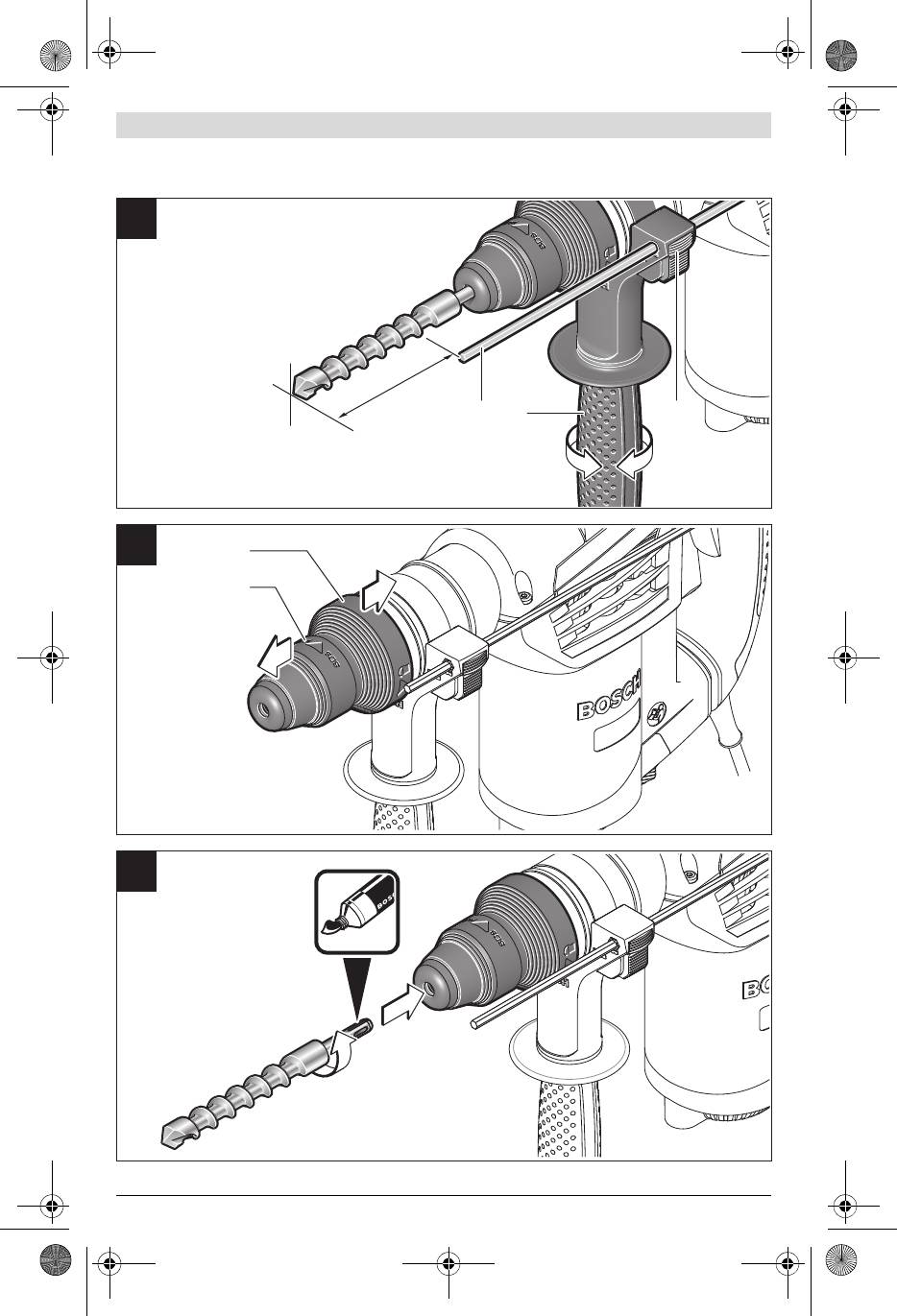
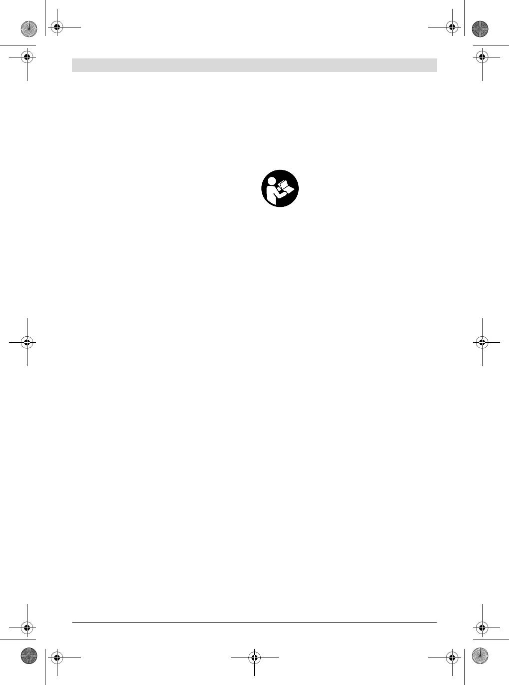
Bohrtiefe einstellen (siehe Bild A)
2
2
Schrauben: a
h
<2,5m/s
, K=1,5 m/s
.
Mit dem Tiefenanschlag 11 kann die gewünschte Bohrtiefe X
Der in diesen Anweisungen angegebene Schwingungspegel ist
festgelegt werden.
entsprechend einem in EN 60745 genormten Messverfahren
– Drücken Sie die Taste für die Tiefenanschlageinstellung 9
gemessen worden und kann für den Vergleich von Elektrowerk-
und setzen Sie den Tiefenanschlag in den Zusatzgriff 10
zeugen miteinander verwendet werden. Er eignet sich auch für
ein.
eine vorläufige Einschätzung der Schwingungsbelastung.
– Schieben Sie das SDS-plus-Einsatzwerkzeug bis zum An-
Der angegebene Schwingungspegel repräsentiert die haupt-
schlag in die Werkzeugaufnahme SDS-plus 1. Die Beweg-
sächlichen Anwendungen des Elektrowerkzeugs. Wenn aller-
lichkeit des SDS-plus-Werkzeugs kann sonst zu einer fal-
dings das Elektrowerkzeug für andere Anwendungen, mit ab-
schen Einstellung der Bohrtiefe führen.
weichenden Einsatzwerkzeugen oder ungenügender Wartung
– Ziehen Sie den Tiefenanschlag so weit heraus, dass der
eingesetzt wird, kann der Schwingungspegel abweichen. Dies
Abstand zwischen der Spitze des Bohrers und der Spitze
kann die Schwingungsbelastung über den gesamten Arbeits-
des Tiefenanschlags der gewünschten Bohrtiefe X ent-
zeitraum deutlich erhöhen.
spricht.
Für eine genaue Abschätzung der Schwingungsbelastung soll-
Die Riffelung am Tiefenanschlag 11 muss nach unten zei-
ten auch die Zeiten berücksichtigt werden, in denen das Gerät
gen.
abgeschaltet ist oder zwar läuft, aber nicht tatsächlich im Ein-
satz ist. Dies kann die Schwingungsbelastung über den gesam-
ten Arbeitszeitraum deutlich reduzieren.
1 609 92A 044 | (10.1.13) Bosch Power Tools
OBJ_BUCH-337-006.book Page 9 Thursday, January 10, 2013 1:23 PM
Deutsch | 9
Werkzeugaufnahme auswählen
Eine beschädigte Staubschutzkappe ist sofort zu erset-
zen. Es wird empfohlen, dies von einem Kundendienst
Zum Hammerbohren benötigen Sie SDS-plus-Werkzeuge, die
vornehmen zu lassen.
in die Werkzeugaufnahme SDS-plus 1 eingesetzt werden.
Zum Bohren ohne Schlag in Holz, Metall, Keramik und Kunst-
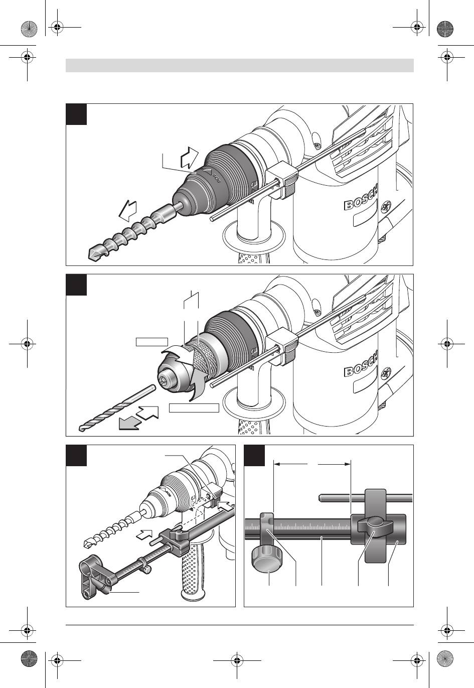
SDS-plus-Einsatzwerkzeug einsetzen (siehe Bild C)
stoff sowie zum Schrauben und Gewindeschneiden werden
– Reinigen Sie das Einsteckende des Einsatzwerkzeuges und
Werkzeuge ohne SDS-plus (z. B. Bohrer mit zylindrischem
fetten Sie es leicht ein.
Schaft) verwendet. Für diese Werkzeuge benötigen Sie ein
– Setzen Sie das Einsatzwerkzeug drehend in die Werkzeug-
Schnellspannbohrfutter.
aufnahme ein, bis es selbsttätig verriegelt wird.
Hinweis: Verwenden Sie Werkzeuge ohne SDS-plus nicht
– Überprüfen Sie die Verriegelung durch Ziehen am Werk-
zum Hammerbohren oder Meißeln! Werkzeuge ohne SDS-
zeug.
plus und ihr Bohrfutter werden beim Hammerbohren und Mei-
SDS-plus-Einsatzwerkzeug entnehmen (siehe Bild D)
ßeln beschädigt.
– Schieben Sie die Verriegelungshülse 3 nach hinten und
Die Werkzeugaufnahme SDS-plus 1 kann leicht gegen das
entnehmen Sie das Einsatzwerkzeug.
Schnellspann-Wechselbohrfutter 13 ausgetauscht werden.
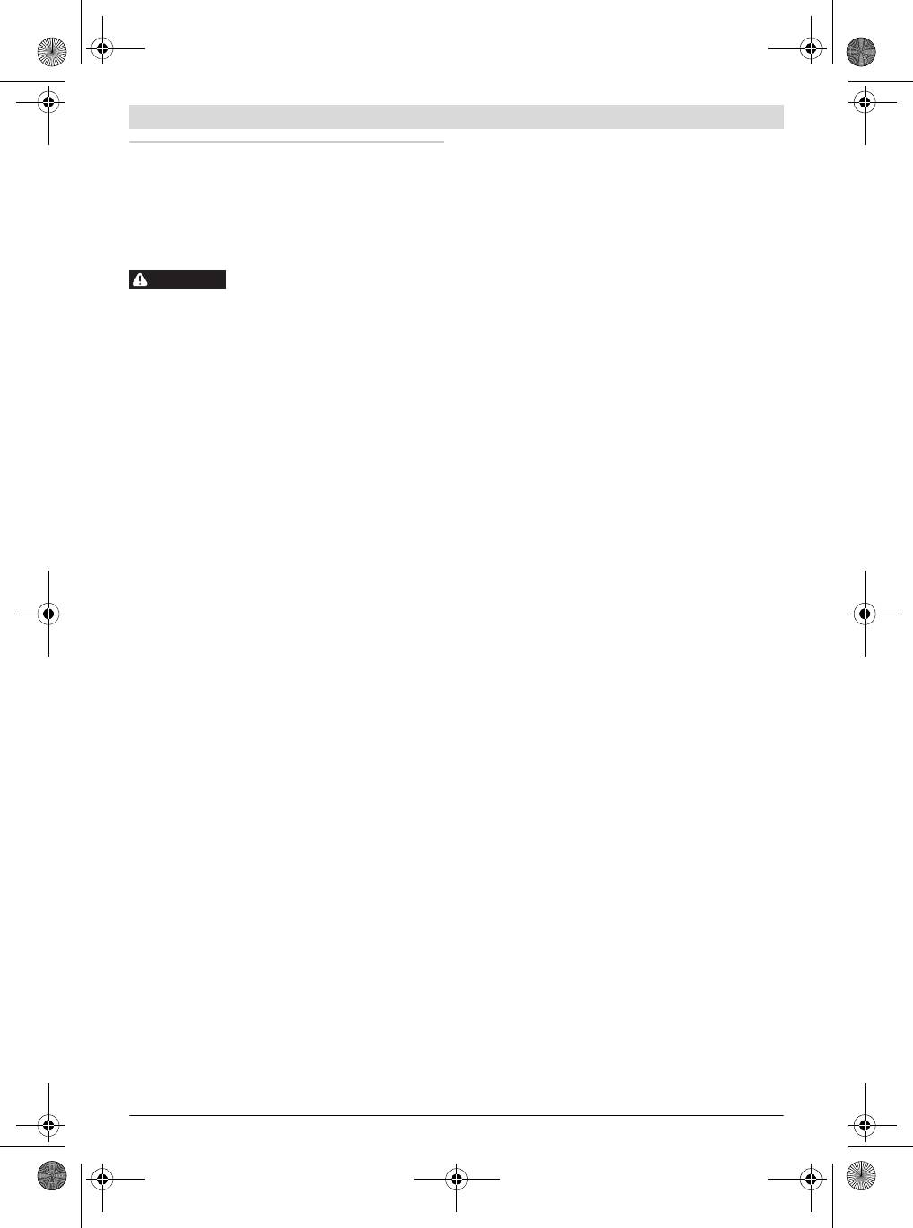
Einsatzwerkzeuge ohne SDS-plus einsetzen (siehe Bild E)
Werkzeugaufnahme wechseln
Hinweis: Verwenden Sie Werkzeuge ohne SDS-plus nicht
zum Hammerbohren oder Meißeln! Werkzeuge ohne SDS-
Werkzeugaufnahme SDS-plus bzw. Schnellspann-Wech-
plus und ihr Bohrfutter werden beim Hammerbohren und Mei-
selbohrfutter demontieren (siehe Bild B)
ßeln beschädigt.
– Ziehen Sie den Verriegelungsring der Werkzeugaufnahme
– Setzen Sie das Schnellspann-Wechselbohrfutter 13 ein.
4 kräftig in Pfeilrichtung, halten Sie ihn in dieser Position
– Halten Sie den Haltering des Schnellspann-Wechselbohr-
fest und ziehen Sie die Werkzeugaufnahme 1 bzw. das
futters 13 fest. Öffnen Sie die Werkzeugaufnahme durch
Schnellspann-Wechselbohrfutter 13 nach vorn ab.
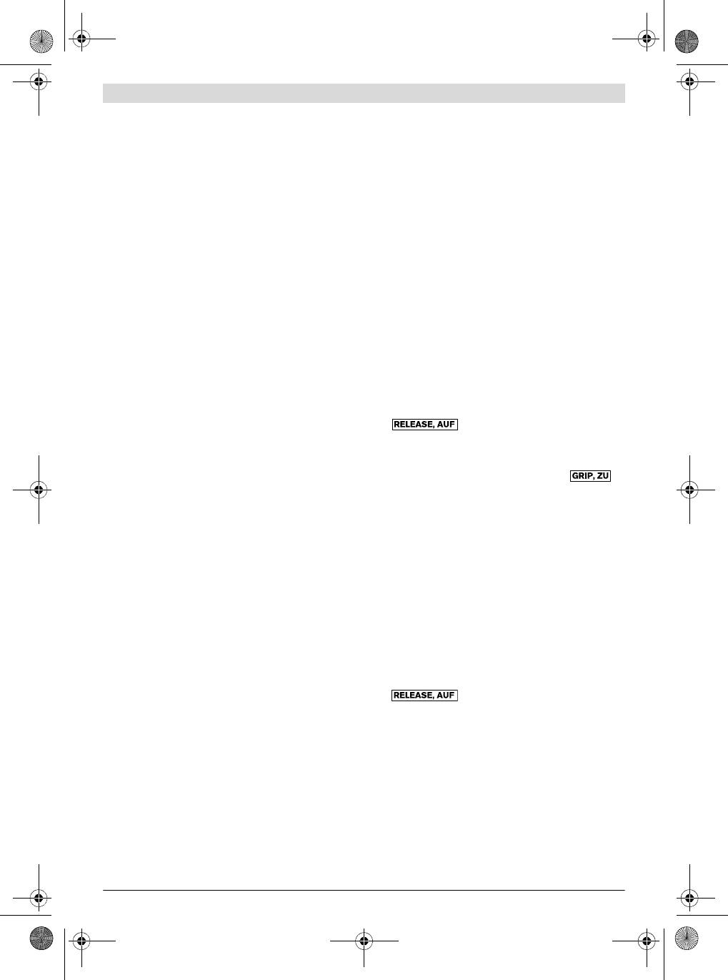
Drehen der vorderen Hülse in Richtung des Symbols
Schützen Sie die Werkzeugaufnahme 1 bzw. das Schnell-
„“.
spann-Wechselbohrfutter 13 nach dem Abnehmen vor Ver-
– Setzen Sie das Einsatzwerkzeug in das Schnellspann-
schmutzung. Schmieren Sie bei Bedarf die Mitnahmeverzah-
Wechselbohrfutter 13 ein. Halten Sie den Haltering des
nung leicht.
Schnellspann-Wechselbohrfutters 13 fest und drehen Sie
Werkzeugaufnahme bzw. Schnellspann-Wechselbohrfut-
die vordere Hülse in Richtung des Symbols „ “.
ter montieren (siehe Bild B)
– Prüfen Sie den festen Sitz durch Ziehen am Werkzeug.
Verwenden Sie nur modellspezifische Originalausstat-
Hinweis: Wurde die Werkzeugaufnahme bis zum Anschlag ge-
tung und achten Sie dabei auf die Anzahl der Kennril-
öffnet, kann beim Zudrehen der Werkzeugaufnahme das Rat-
len. Es sind nur Wechselbohrfutter mit zwei Kennrillen
schengeräusch zu hören sein und die Werkzeugaufnahme
zulässig. Wird ein für dieses Elektrowerkzeug nicht geeig-
schließt sich nicht.
netes Wechselbohrfutter verwendet, kann das Einsatz-
Drehen Sie in diesem Fall die vordere Hülse 14 einmal entge-
werkzeug während des Betriebs herausfallen.
gen der Pfeilrichtung. Danach kann die Werkzeugaufnahme
– Umgreifen Sie die Werkzeugaufnahme 1 bzw. das Schnell-
geschlossen werden.
spann-Wechselbohrfutter 13 mit der ganzen Hand. Schie-
– Drehen Sie den Schlag-/Drehstopp-Schalter 5 in die Posi-
ben Sie die Werkzeugaufnahme 1 bzw. das Schnellspann-
tion „Bohren“.
Wechselbohrfutter 13 drehend auf die Bohrfutteraufnah-
Einsatzwerkzeuge ohne SDS-plus entnehmen
me, bis Sie ein deutliches Einrastgeräusch hören.
(siehe Bild E)
– Die Werkzeugaufnahme 1 bzw. das Schnellspann-Wech-
– Halten Sie den Haltering des Schnellspann-Wechselbohr-
selbohrfutter 13 verriegelt sich selbsttätig. Überprüfen
futters 13 fest. Öffnen Sie die Werkzeugaufnahme durch
Sie die Verriegelung durch Ziehen an der Werkzeugaufnah-
Drehen der vorderen Hülse in Richtung des Symbols
me.
„“.
Werkzeugwechsel
– Entnehmen Sie das Einsatzwerkzeug.
Mit der Werkzeugaufnahme SDS-plus können Sie das Einsatz-
Staubabsaugung mit Saugfix (Zubehör)
werkzeug einfach und bequem ohne Verwendung zusätzli-
Stäube von Materialien wie bleihaltigem Anstrich, einigen
cher Werkzeuge wechseln.
Holzarten, Mineralien und Metall können gesundheits-
Das SDS-plus-Einsatzwerkzeug ist systembedingt frei beweg-
schädlich sein. Berühren oder Einatmen der Stäube kön-
lich. Dadurch entsteht beim Leerlauf eine Rundlaufabwei-
nen allergische Reaktionen und/oder Atemwegserkran-
chung. Dies hat keine Auswirkungen auf die Genauigkeit des
kungen des Benutzers oder in der Nähe befindlicher
Bohrlochs, da sich der Bohrer beim Bohren selbst zentriert.
Personen hervorrufen.
Bestimmte Stäube wie Eichen- oder Buchenstaub gelten
Die Staubschutzkappe 2 verhindert weitgehend das Eindrin-
als krebserzeugend, besonders in Verbindung mit Zusatz-
gen von Bohrstaub in die Werkzeugaufnahme während des
stoffen zur Holzbehandlung (Chromat, Holzschutzmittel).
Betriebes. Achten Sie beim Einsetzen des Werkzeuges dar-
Asbesthaltiges Material darf nur von Fachleuten bearbeitet
auf, dass die Staubschutzkappe 2 nicht beschädigt wird.
werden.
Bosch Power Tools 1 609 92A 044 | (10.1.13)
OBJ_BUCH-337-006.book Page 10 Thursday, January 10, 2013 1:23 PM
10 | Deutsch
– Benutzen Sie möglichst eine für das Material geeignete
Betriebsart einstellen
Staubabsaugung.
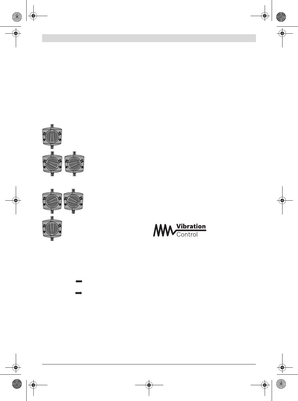
Mit dem Schlag-/Drehstopp-Schalter 5 wählen Sie die Be-
– Sorgen Sie für gute Belüftung des Arbeitsplatzes.
triebsart des Elektrowerkzeugs.
– Es wird empfohlen, eine Atemschutzmaske mit Filter-
Hinweis: Ändern Sie die Betriebsart nur bei ausgeschaltetem
klasse P2 zu tragen.
Elektrowerkzeug! Das Elektrowerkzeug kann sonst beschä-
Beachten Sie in Ihrem Land gültige Vorschriften für die zu
digt werden.
bearbeitenden Materialien.
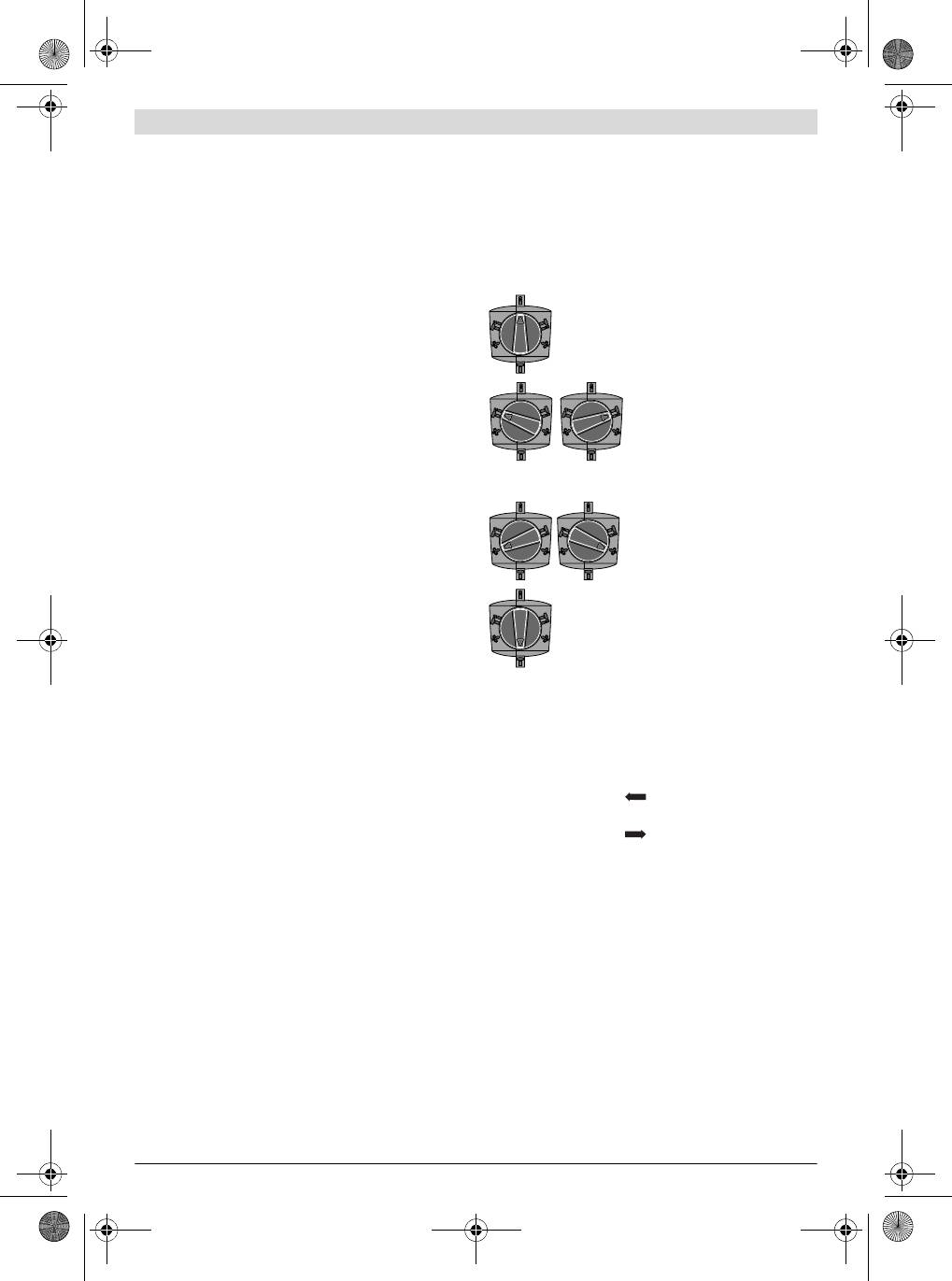
– Drehen Sie den Schlag-/Drehstopp-Schalter 5 auf die ge-
Vermeiden Sie Staubansammlungen am Arbeitsplatz.
wünschte Stellung.
Stäube können sich leicht entzünden.
Saugfix montieren (siehe Bild F)
Position zum Bohren ohne
Für die Staubabsaugung wird ein Saugfix (Zubehör) benötigt.
Schlag in Holz, Metall, Keramik
Beim Bohren federt der Saugfix zurück, sodass der Saugfix-
und Kunststoff sowie zum
Kopf immer dicht am Untergrund gehalten wird.
Schrauben
– Drücken Sie die Taste für die Tiefenanschlageinstellung 9
Position zum Hammerbohren in
und entnehmen Sie den Tiefenanschlag 11. Drücken Sie
Beton oder Stein
die Taste 9 erneut und setzen Sie den Saugfix von vorn in
Falls sich das Einsatzwerkzeug
den Zusatzgriff 10 ein.
beim Einschalten nicht sofort
– Schließen Sie einen Absaugschlauch (Durchmesser
dreht, lassen Sie das Elektro-
19 mm, Zubehör) an die Absaugöffnung 16 des Saugfix
werkzeug langsam laufen, bis sich
an.
das Einsatzwerkzeug mitdreht.
Der Staubsauger muss für den zu bearbeitenden Werkstoff
geeignet sein.
Position Vario-Lock zum Verstel-
Verwenden Sie beim Absaugen von besonders gesundheits-
len der Meißelposition
gefährdenden, krebserzeugenden oder trockenen Stäuben
einen Spezialsauger.
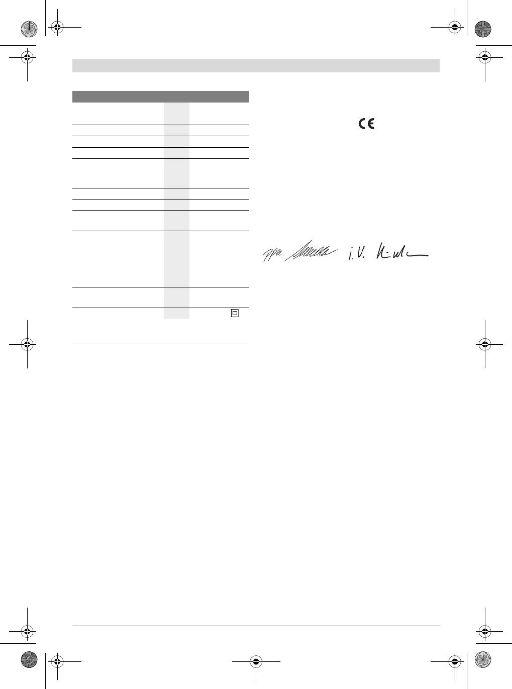
Bohrtiefe am Saugfix einstellen (siehe Bild G)
Sie können die gewünschte Bohrtiefe X auch bei montiertem
Position zum Meißeln
Saugfix festlegen.
– Schieben Sie das SDS-plus-Einsatzwerkzeug bis zum An-
schlag in die Werkzeugaufnahme SDS-plus 1. Die Beweg-
Drehrichtung einstellen
lichkeit des SDS-plus-Werkzeugs kann sonst zu einer fal-
schen Einstellung der Bohrtiefe führen.
Betätigen Sie den Drehrichtungsumschalter 8 nur bei
– Lösen Sie die Flügelschraube 20 am Saugfix.
Stillstand des Elektrowerkzeuges.
– Setzen Sie das Elektrowerkzeug ohne es einzuschalten
Mit dem Drehrichtungsumschalter 8 können Sie die Drehrich-
fest auf die zu bohrende Stelle auf. Das SDS-plus-Einsatz-
tung des Elektrowerkzeuges ändern.
werkzeug muss dabei auf der Fläche aufsetzen.
Rechtslauf: Drehen Sie den Drehrichtungsumschalter 8 bis
– Verschieben Sie das Führungsrohr 21 des Saugfix so in
zum Anschlag in Position .
seiner Halterung, dass der Saugfix-Kopf auf der zu bohren-
Linkslauf: Drehen Sie den Drehrichtungsumschalter 8 bis
den Fläche aufliegt. Schieben Sie das Führungsrohr 21
zum Anschlag in Position .
nicht weiter über das Teleskoprohr 19 als nötig, sodass ein
möglichst großer Teil der Skala auf dem Teleskoprohr 19
Stellen Sie die Drehrichtung zum Hammerbohren, Bohren
sichtbar bleibt.
und Meißeln immer auf Rechtslauf.
– Ziehen Sie die Flügelschraube 20 wieder fest. Lösen Sie
Ein-/Ausschalten
die Klemmschraube 17 am Tiefenanschlag des Saugfix.
– Drücken Sie zur Inbetriebnahme des Elektrowerkzeuges
– Verschieben Sie den Tiefenanschlag 18 so auf dem Teles-
den Ein-/Ausschalter 7 und halten Sie ihn gedrückt.
koprohr 19, dass der im Bild gezeigte Abstand X Ihrer ge-
– Um das Elektrowerkzeug auszuschalten, lassen Sie den
wünschten Bohrtiefe entspricht.
Ein-/Ausschalter 7 los.
– Ziehen Sie die Klemmschraube 17 in dieser Position fest.
Bei niedrigen Temperaturen erreicht das Elektrowerkzeug
erst nach einer gewissen Zeit die volle Hammerleis-
Betrieb
tung/Schlagleistung.
Um Energie zu sparen, schalten Sie das Elektrowerkzeug nur
Inbetriebnahme
ein, wenn Sie es benutzen.
Beachten Sie die Netzspannung! Die Spannung der
Drehzahl/Schlagzahl einstellen
Stromquelle muss mit den Angaben auf dem Typen-
Sie können die Drehzahl/Schlagzahl des eingeschalteten
schild des Elektrowerkzeuges übereinstimmen. Mit
Elektrowerkzeugs stufenlos regulieren, je nachdem, wie weit
230 V gekennzeichnete Elektrowerkzeuge können
Sie den Ein-/Ausschalter 7 eindrücken.
auch an 220 V betrieben werden.
1 609 92A 044 | (10.1.13) Bosch Power Tools
OBJ_BUCH-337-006.book Page 11 Thursday, January 10, 2013 1:23 PM
Deutsch | 11
Leichter Druck auf den Ein-/Ausschalter 7 bewirkt eine nied-
Geben Sie bei allen Rückfragen und Ersatzteilbestellungen
rige Drehzahl/Schlagzahl. Mit zunehmendem Druck erhöht
bitte unbedingt die 10-stellige Sachnummer laut Typenschild
sich die Drehzahl/Schlagzahl.
des Elektrowerkzeuges an.
Überlastkupplung
Kundendienst und Anwendungsberatung
Klemmt oder hakt das Einsatzwerkzeug, wird der An-
Der Kundendienst beantwortet Ihre Fragen zu Reparatur und
trieb zur Bohrspindel unterbrochen. Halten Sie, wegen
Wartung Ihres Produkts sowie zu Ersatzteilen. Explosions-
der dabei auftretenden Kräfte, das Elektrowerkzeug
zeichnungen und Informationen zu Ersatzteilen finden Sie
immer mit beiden Händen gut fest und nehmen Sie ei-
auch unter:
nen festen Stand ein.
www.bosch-pt.com
Schalten Sie das Elektrowerkzeug aus und lösen Sie
Das Bosch-Anwendungsberatungs-Team hilft Ihnen gerne bei
das Einsatzwerkzeug, wenn das Elektrowerkzeug blo-
Fragen zu unseren Produkten und deren Zubehör.
ckiert. Beim Einschalten mit einem blockierten Bohr-
www.powertool-portal.de, das Internetportal für Handwer-
werkzeug entstehen hohe Reaktionsmomente.
ker und Heimwerker.
Verändern der Meißelstellung (Vario-Lock)
Deutschland
Sie können den Meißel in 13 Stellungen arretieren. Dadurch
Robert Bosch GmbH
können Sie die jeweils optimale Arbeitsposition einnehmen.
Servicezentrum Elektrowerkzeuge
– Setzen Sie den Meißel in die Werkzeugaufnahme ein.
Zur Luhne 2
– Drehen Sie den Schlag-/Drehstopp-Schalter 5 in die Posi-
37589 Kalefeld – Willershausen
tion „Vario-Lock“ (siehe „Betriebsart einstellen“,
Unter www.bosch-pt.com können Sie online Ersatzteile be-
Seite 10).
stellen oder Reparaturen anmelden.
– Drehen Sie das Einsatzwerkzeug in die gewünschte Mei-
Kundendienst: Tel.: (0711) 40040480
ßelstellung.
Fax: (0711) 40040481
– Drehen Sie den Schlag-/Drehstopp-Schalter 5 in die Posi-
E-Mail: Servicezentrum.Elektrowerkzeuge@de.bosch.com
tion „Meißeln“. Die Werkzeugaufnahme ist damit arretiert.
Anwendungsberatung: Tel.: (0711) 40040480
– Stellen Sie die Drehrichtung zum Meißeln auf Rechtslauf.
Fax: (0711) 40040482
E-Mail: Anwendungsberatung.pt@de.bosch.com
Arbeitshinweise
Österreich
Ziehen Sie vor allen Arbeiten am Elektrowerkzeug den
Netzstecker aus der Steckdose.
Tel.: (01) 797222010
Fax: (01) 797222011
Vibrationsdämpfung
E-Mail: service.elektrowerkzeuge@at.bosch.com
Schweiz
Tel.: (044) 8471511
Fax: (044) 8471551
Die integrierte Vibrationsdämpfung reduziert auftretende Vi-
E-Mail: Aftersales.Service@de.bosch.com
brationen.
Luxemburg
Wartung und Service
Tel.: +32 2 588 0589
Fax: +32 2 588 0595
Wartung und Reinigung
E-Mail: outillage.gereedschap@be.bosch.com
Ziehen Sie vor allen Arbeiten am Elektrowerkzeug den
Entsorgung
Netzstecker aus der Steckdose.
Elektrowerkzeuge, Zubehör und Verpackungen sollen einer
Halten Sie das Elektrowerkzeug und die Lüftungs-
umweltgerechten Wiederverwertung zugeführt werden.
schlitze sauber, um gut und sicher zu arbeiten.
Werfen Sie Elektrowerkzeuge nicht in den Hausmüll!
Eine beschädigte Staubschutzkappe ist sofort zu erset-
Nur für EU-Länder:
zen. Es wird empfohlen, dies von einem Kundendienst
vornehmen zu lassen.
Gemäß der Europäischen Richtlinie
2002/96/EG über Elektro- und Elektronik-
Wenn ein Ersatz der Anschlussleitung erforderlich ist, dann
Altgeräte und ihrer Umsetzung in nationales
ist dies von Bosch oder einer autorisierten Kundendienststel-
Recht müssen nicht mehr gebrauchsfähige
le für Bosch-Elektrowerkzeuge auszuführen, um Sicherheits-
Elektrowerkzeuge getrennt gesammelt und
gefährdungen zu vermeiden.
einer umweltgerechten Wiederverwertung
Sollte das Elektrowerkzeug trotz sorgfältiger Herstellungs-
zugeführt werden.
und Prüfverfahren einmal ausfallen, ist die Reparatur von ei-
ner autorisierten Kundendienststelle für Bosch-Elektrowerk-
Änderungen vorbehalten.
zeuge ausführen zu lassen.
Bosch Power Tools 1 609 92A 044 | (10.1.13)
OBJ_BUCH-337-006.book Page 12 Thursday, January 10, 2013 1:23 PM
12 | English
Prevent unintentional starting. Ensure the switch is in
English
the off-position before connecting to power source
and/or battery pack, picking up or carrying the tool.
Safety Notes
Carrying power tools with your finger on the switch or en-
ergising power tools that have the switch on invites acci-
General Power Tool Safety Warnings
dents.
Read all safety warnings and all in-
WARNING
Remove any adjusting key or wrench before turning
structions. Failure to follow the warnings
the power tool on. A wrench or a key left attached to a ro-
and instructions may result in electric shock, fire and/or seri-
tating part of the power tool may result in personal injury.
ous injury.
Do not overreach. Keep proper footing and balance at
Save all warnings and instructions for future reference.
all times. This enables better control of the power tool in
The term “power tool” in the warnings refers to your mains-
unexpected situations.
operated (corded) power tool or battery-operated (cordless)
Dress properly. Do not wear loose clothing or jewel-
power tool.
lery. Keep your hair, clothing and gloves away from
Work area safety
moving parts. Loose clothes, jewellery or long hair can be
Keep work area clean and well lit. Cluttered or dark areas
caught in moving parts.
invite accidents.
If devices are provided for the connection of dust ex-
Do not operate power tools in explosive atmospheres,
traction and collection facilities, ensure these are con-
such as in the presence of flammable liquids, gases or
nected and properly used. Use of dust collection can re-
dust. Power tools create sparks which may ignite the dust
duce dust-related hazards.
or fumes.
Power tool use and care
Keep children and bystanders away while operating a
Do not force the power tool. Use the correct power tool
power tool. Distractions can cause you to lose control.
for your application. The correct power tool will do the
Electrical safety
job better and safer at the rate for which it was designed.
Power tool plugs must match the outlet. Never modify
Do not use the power tool if the switch does not turn it
the plug in any way. Do not use any adapter plugs with
on and off. Any power tool that cannot be controlled with
earthed (grounded) power tools. Unmodified plugs and
the switch is dangerous and must be repaired.
matching outlets will reduce risk of electric shock.
Disconnect the plug from the power source and/or the
Avoid body contact with earthed or grounded surfaces,
battery pack from the power tool before making any
such as pipes, radiators, ranges and refrigerators.
adjustments, changing accessories, or storing power
There is an increased risk of electric shock if your body is
tools. Such preventive safety measures reduce the risk of
earthed or grounded.
starting the power tool accidentally.
Do not expose power tools to rain or wet conditions.
Store idle power tools out of the reach of children and
Water entering a power tool will increase the risk of electric
do not allow persons unfamiliar with the power tool or
shock.
these instructions to operate the power tool. Power
tools are dangerous in the hands of untrained users.
Do not abuse the cord. Never use the cord for carrying,
pulling or unplugging the power tool. Keep cord away
Maintain power tools. Check for misalignment or bind-
from heat, oil, sharp edges and moving parts. Damaged
ing of moving parts, breakage of parts and any other
or entangled cords increase the risk of electric shock.
condition that may affect the power tool’s operation. If
damaged, have the power tool repaired before use.
When operating a power tool outdoors, use an exten-
Many accidents are caused by poorly maintained power
sion cord suitable for outdoor use. Use of a cord suitable
tools.
for outdoor use reduces the risk of electric shock.
Keep cutting tools sharp and clean. Properly maintained
If operating a power tool in a damp location is unavoid-
cutting tools with sharp cutting edges are less likely to bind
able, use a residual current device (RCD) protected
and are easier to control.
supply. Use of an RCD reduces the risk of electric shock.
Use the power tool, accessories and tool bits etc. in ac-
Personal safety
cordance with these instructions, taking into account
Stay alert, watch what you are doing and use common
the working conditions and the work to be performed.
sense when operating a power tool. Do not use a power
Use of the power tool for operations different from those
tool while you are tired or under the influence of drugs,
intended could result in a hazardous situation.
alcohol or medication. A moment of inattention while op-
Service
erating power tools may result in serious personal injury.
Have your power tool serviced by a qualified repair per-
Use personal protective equipment. Always wear eye
son using only identical replacement parts. This will en-
protection. Protective equipment such as dust mask,
sure that the safety of the power tool is maintained.
non-skid safety shoes, hard hat, or hearing protection
used for appropriate conditions will reduce personal inju-
ries.
1 609 92A 044 | (10.1.13) Bosch Power Tools
OBJ_BUCH-337-006.book Page 13 Thursday, January 10, 2013 1:23 PM
English | 13
Hammer Safety Warnings
Product Features
Wear ear protectors. Exposure to noise can cause hear-
The numbering of the product features refers to the illustra-
ing loss.
tion of the machine on the graphics page.
Use auxiliary handle(s), if supplied with the tool. Loss
1 SDS-plus tool holder
of control can cause personal injury.
2 Dust protection cap
Hold the tool by the insulated gripping surfaces when
3 Locking sleeve
performing operations where the application tool or
4 Lock ring of the tool holder
the screw could contact hidden wiring or its own power
5 Mode selector switch
cord. Contact with a “live” wire will also make exposed
6 Vibration damper
metal parts of the power tool “live” and shock the operator.
7 On/Off switch
Use suitable detectors to determine if utility lines are
hidden in the work area or call the local utility company
8 Rotational direction switch
for assistance. Contact with electric lines can lead to fire
9 Button for depth stop adjustment
and electric shock. Damaging a gas line can lead to explo-
10 Auxiliary handle (insulated gripping surface)
sion. Penetrating a water line causes property damage or
11 Depth stop
may cause an electric shock.
12 Handle (insulated gripping surface)
When working with the machine, always hold it firmly
13 Quick change keyless chuck*
with both hands and provide for a secure stance. The
14 Front sleeve of the quick change keyless chuck*
power tool is guided more secure with both hands.
15 Retaining ring of the quick change keyless chuck*
Secure the workpiece. A workpiece clamped with clamp-
16 Extraction sleeve of the dust extraction attachment*
ing devices or in a vice is held more secure than by hand.
17 Clamping screw for the dust extraction attachment*
Always wait until the machine has come to a complete
stop before placing it down. The tool insert can jam and
18 Depth stop of the dust extraction attachment*
lead to loss of control over the power tool.
19 Telescopic pipe of the dust extraction attachment*
Products sold in GB only: Your product is fitted with an
20 Wing bolt of the dust extraction attachment*
BS 1363/A approved electric plug with internal fuse (ASTA
21 Guide pipe of the dust extraction attachment*
approved to BS 1362).
*Accessories shown or described are not part of the standard de-
If the plug is not suitable for your socket outlets, it should be
livery scope of the product. A complete overview of accessories
cut off and an appropriate plug fitted in its place by an author-
can be found in our accessories program.
ised customer service agent. The replacement plug should
Technical Data
have the same fuse rating as the original plug.
The severed plug must be disposed of to avoid a possible
Rotary Hammer GBH 4-32 DFR
shock hazard and should never be inserted into a mains sock-
Article number
3 611 C32 0..
et elsewhere.
Products sold in AUS and NZ only: Use a residual current de-
3 611 C32 1..
vice (RCD) with a rated residual current of 30 mA or less.
Rated power input
W900
-1
Speed
min
0–760
-1
Product Description and Specifica-
Impact rate
min
0 –3600
tions
Impact energy per stroke ac-
cording to EPTA-Procedure
Read all safety warnings and all instruc-
05/2009
J4.2
tions. Failure to follow the warnings and in-
Chisel positions
12
structions may result in electric shock, fire
and/or serious injury.
Tool holder
SDS-plus
Lubrication
Central permanent
While reading the operating instructions, unfold the graphics
lubrication
page for the machine and leave it open.
Max. drilling dia.
– Concrete (with twist drill)
mm
32
Intended Use
– Brickwork (with core bit)
mm
90
The machine is intended for hammer drilling in concrete,
– Steel
mm
13
brick and stone, as well as for light chiselling work. It is also
– Wood
mm
32
suitable for drilling without impact in wood, metal, ceramic
Weight according to
and plastic. Machines with electronic control and right/left ro-
EPTA-Procedure 01/2003
kg 4.7
tation are also suitable for screwdriving.
Protection class
/II
The values given are valid for a nominal voltage [U] of 230 V. For differ-
ent voltages and models for specific countries, these values can vary.
Bosch Power Tools 1 609 92A 044 | (10.1.13)
OBJ_BUCH-337-006.book Page 14 Thursday, January 10, 2013 1:23 PM
14 | English
Noise/Vibration Information
– Turn the bottom part of the auxiliary handle 10 in counter-
clockwise direction and swivel the auxiliary handle 10 to
Measured sound values determined according to EN 60745.
the desired position. Then retighten the bottom part of the
Typically the A-weighted noise levels of the product are:
auxiliary handle 10 by turning in clockwise direction.
Sound pressure level 93 dB(A); Sound power level
104 dB(A). Uncertainty K =3 dB.
Adjusting the Drilling Depth (see figureA)
Wear hearing protection!
The required drilling depth
X
can be set with the depth stop
11
.
Vibration total values a
h
(triax vector sum) and uncertainty K
– Press the button for the depth stop adjustment 9 and in-
determined according to EN 60745:
sert the depth stop into the auxiliary handle 10.
2
2
Hammer drilling into concrete: a
h
=12m/s
, K=1.5 m/s
,
– Insert the SDS-plus drilling tool to the stop into the SDS-
2
2
Chiselling: a
h
=9m/s
, K=1.5 m/s
,
plus tool holder 1. Otherwise, the movability of the SDS-
2
2
Drilling in metal: a
h
<2.5m/s
, K=1.5 m/s
,
plus drilling tool can lead to incorrect adjustment of the
2
2
Screwdriving without impact: a
h
<2.5m/s
, K=1.5 m/s
drilling depth.
The vibration emission level given in this information sheet
– Pull out the depth stop until the distance between the tip of
has been measured in accordance with a standardised test
the drill bit and the tip of the depth stop correspond with
given in EN 60745 and may be used to compare one tool with
the desired drilling depth X.
another. It may be used for a preliminary assessment of expo-
The knurled surface of the depth stop 11 must face down-
sure.
ward.
The declared vibration emission level represents the main ap-
Selecting the Tool Holder
plications of the tool. However if the tool is used for different
applications, with different accessories or poorly maintained,
For hammer drilling, SDS-plus drilling tools that can be insert-
the vibration emission may differ. This may significantly in-
ed into the SDS-plus tool holder 1 are required.
crease the exposure level over the total working period.
For drilling without impact in wood, metal, ceramic and plas-
An estimation of the level of exposure to vibration should also
tic as well as for screwdriving and tapping, use non-SDS-plus
take into account the times when the tool is switched off or
drilling tools (e. g., drill bits with cylindrical shank). A keyless
when it is running but not actually doing the job. This may sig-
drill chuck is required for such drilling tools.
nificantly reduce the exposure level over the total working pe-
Note: Do not use tools without SDS-plus for hammer drilling
riod.
or chiselling! Tools without SDS-plus and their drill chucks are
Identify additional safety measures to protect the operator
damaged by hammer drilling or chiselling.
from the effects of vibration such as: maintain the tool and the
The SDS-plus tool holder 1 can easily be exchanged against
accessories, keep hands warm, organise work patterns.
the quick change keyless chuck 13.
Declaration of Conformity
Changing the Tool Holder
We declare under our sole responsibility that the product de-
scribed under “Technical Data” is in conformity with the fol-
Dismounting the SDS-plus Tool Holder or the Quick
lowing standards or standardization documents: EN 60745
change keyless chuck (see figure B)
according to the provisions of the directives 2011/65/EU,
– Pull the lock ring of the tool holder 4 firmly in the direction
2004/108/EC, 2006/42/EC.
of the arrow, hold it in this position and pull off the tool
Technical file (2006/42/EC) at:
holder 1 or the keyless replacement chuck 13 toward the
Robert Bosch GmbH, PT/ETM9,
front.
D-70745 Leinfelden-Echterdingen
After removing, protect the tool holder 1 or the quick change
Dr. Egbert Schneider
Helmut Heinzelmann
keyless chuck 13 against contamination. Lightly lubricate the
Senior Vice President
Head of Product Certification
engaging grooves, if required.
Engineering
PT/ETM9
Mounting the SDS-plus Tool Holder or the Quick change
keyless chuck (see figure B)
Use only model-specific original equipment and pay at-
tention to the number of identification grooves. Only
Robert Bosch GmbH, Power Tools Division
quick-change chucks with two identification grooves
D-70745 Leinfelden-Echterdingen
are permitted. When an unsuitable quick-change chuck is
Leinfelden, 14.12.2012
used, the application tool could fall out during operation.
– Grasp the tool holder 1 or the keyless replacement chuck
Assembly
13 completely with your hand. Slide the tool holder 1 or
Before any work on the machine itself, pull the mains
the keyless replacement chuck 13 with a turning motion
plug.
onto the drill chuck mounting until a distinct latching noice
Auxiliary Handle
is heard.
Operate your machine only with the auxiliary handle 10.
– The tool holder 1 or the quick change keyless chuck 13 is
automatically locked. Check the locking effect by pulling
The auxiliary handle 10 can be set to any position for a secure
the tool holder.
and low-fatigue working posture.
1 609 92A 044 | (10.1.13) Bosch Power Tools
OBJ_BUCH-337-006.book Page 15 Thursday, January 10, 2013 1:23 PM
English | 15
Changing the Tool
Certain dusts, such as oak or beech dust, are considered
as carcinogenic, especially in connection with wood-treat-
With the SDS-plus tool holder, simple and convenient tool
ment additives (chromate, wood preservative). Materials
changing is possible without additional aids.
containing asbestos may only be worked by specialists.
As a requirement of the system, the SDS-plus drilling tool can
– As far as possible, use a dust extraction system suita-
move freely. This causes a certain radial run-out at no-load,
ble for the material.
which has no effect on the accuracy of the drill hole, as the
– Provide for good ventilation of the working place.
drill bit centres itself upon drilling.
– It is recommended to wear a P2 filter-class respirator.
The dust protection cap 2 largely prevents the entry of drilling
Observe the relevant regulations in your country for the
dust into the tool holder during operation. When inserting the
materials to be worked.
tool, take care that the dust protection cap 2 is not damaged.
Prevent dust accumulation at the workplace. Dusts can
A damaged dust protection cap should be changed im-
easily ignite.
mediately. We recommend having this carried out by
Mounting the Dust Extraction Attachment (see figure F)
an after-sales service.
For dust extraction, the dust extraction attachment (accesso-
Inserting SDS-plus Drilling Tools (see figure C)
ry) is required. When drilling, the dust extraction attachment
– Clean and lightly grease the shank end of the tool.
retracts so that the attachment head is always close to the
– Insert the tool in a twisting manner into the tool holder until
surface at the drill hole.
it latches itself.
– Press the button for depth stop adjustment 9 and remove
– Check the latching by pulling the tool.
the depth stop 11. Press button 9 again and insert the dust
Removing SDS-plus Drilling Tools (see figure D)
extraction attachment into the auxiliary handle 10 from the
– Push back the locking sleeve 3 and remove the tool.
front.
– Connect an extraction hose (diameter 19 mm, accessory)
Inserting Drilling Tools without SDS-plus (see figure E)
to the extraction sleeve 16 of the dust extraction attach-
Note: Do not use tools without SDS-plus for hammer drilling
ment.
or chiselling! Tools without SDS-plus and their drill chucks are
The vacuum cleaner must be suitable for the material being
damaged by hammer drilling or chiselling.
worked.
– Insert the quick change keyless chuck 13.
When vacuuming dry dust that is especially detrimental to
– Firmly hold the retaining ring of the quick change keyless
health or carcinogenic, use a special vacuum cleaner.
chuck 13. Open the quick change keyless chuck by turning
the front sleeve in the direction of the symbol
Adjusting the Drilling Depth on the Dust Extraction At-
“”.
tachment (see figure G)
– Insert the drilling tool into the quick change keyless chuck
The required drilling depth X can also be adjusted when the
13. Firmly hold the retaining ring of the quick change key-
dust extraction attachment is mounted.
less chuck 13 and turn the front sleeve in the direction of
– Insert the SDS-plus drilling tool to the stop into the SDS-
the symbol “ ”.
plus tool holder 1. Otherwise, the movability of the SDS-
– Check the tight seating by pulling the tool.
plus drilling tool can lead to incorrect adjustment of the
Note: If the tool holder was opened to the stop, then the latch-
drilling depth.
ing noise possibly may be heard while closing the tool holder
– Loosen the wing bolt 20 on the dust extraction attach-
and the tool holder will not close.
ment.
In this case, turn the front sleeve 14 once in the opposite di-
– Without switching the power tool on, apply it firmly to the
rection of the arrow. Afterwards, the tool holder can be
drilling location. The SDS-plus drilling tool must face
closed (tightened) again.
against the surface.
– Turn the mode selector switch 5 to the “drilling” position.
– Position the the guide pipe 21 of the dust extraction at-
tachment in its holding fixture in such a manner that the
Removing Drilling Tools without SDS-plus (see figure E)
head of the dust extraction attachment faces against the
– Firmly hold the retaining ring of the quick change keyless
surface to be drilled. Do not slide the guide pipe 21 further
chuck 13. Open the quick change keyless chuck by turning
over the telescopic pipe 19 of the dust extraction attach-
the front sleeve in the direction of the symbol
ment than required, so that as much as possible of the
“”.
scale 19 on the telescopic pipe remains visible.
– Remove the drilling tool.
– Retighten the wing bolt 20 again. Loosen the clamping
screw 17 on the depth stop of the dust extraction attach-
Dust Extraction with the Dust Extraction Attach-
ment.
ment (Accessory)
– Move the depth stop 18 on the telescopic pipe
19 in such
Dusts from materials such as lead-containing coatings,
a manner that the clearance X shown in the figure corre-
some wood types, minerals and metal can be harmful to
sponds with the required drilling depth.
one’s health. Touching or breathing-in the dusts can cause
– Tighten the clamping screw 17 in this position.
allergic reactions and/or lead to respiratory infections of
the user or bystanders.
Bosch Power Tools 1 609 92A 044 | (10.1.13)
OBJ_BUCH-337-006.book Page 16 Thursday, January 10, 2013 1:23 PM
16 | English
Operation
Setting the Speed/Impact Rate
The speed/impact rate of the switched on power tool can be
Starting Operation
variably adjusted, depending on how far the On/Off switch 7
is pressed.
Observe correct mains voltage! The voltage of the pow-
er source must agree with the voltage specified on the
Light pressure on the On/Off switch 7 results in low speed/im-
nameplate of the machine. Power tools marked with
pact rate. Further pressure on the switch increases the
230 V can also be operated with 220 V.
speed/impact rate.
Setting the operating mode
Safety Clutch
The operating mode of the power tool is selected with the
If the tool insert becomes caught or jammed, the drive
mode selector switch 5.
to the drill spindle is interrupted. Because of the forces
that occur, always hold the power tool firmly with both
Note: Change the operating mode only when the machine is
hands and provide for a secure stance.
switched off! Otherwise, the machine can be damaged.
If the power tool jams, switch the machine off and loos-
– Turn the mode selector switch 5 to the requested position.
en the tool insert. When switching the machine on with
the drilling tool jammed, high reaction torques can oc-
Position for drilling without im-
cur.
pact in wood, metal, ceramic and
plastic as well as for screwdriving
Changing the Chiselling Position (Vario-Lock)
The chisel can be locked in 13 positions. In this manner, the
Position for hammer drilling in
optimum working position can be set for each application.
concrete or stone
– Insert the chisel into the tool holder.
When the drilling tool does not
– Turn the mode selector switch 5 to the “Vario-Lock” posi-
immediately rotate upon switch-
tion (see “Setting the operating mode”, page 16).
ing on, allow the machine to run
– Turn the tool holder to the desired chiselling position.
slowly until the drilling tool ro-
– Turn the mode selector switch 5 to the “chiselling” posi-
tates.
tion. The tool holder is now locked.
– For chiselling, set the rotation direction to right rotation.
Vario-Lock position for adjust-
Working Advice
ment of the chiselling position
Before any work on the machine itself, pull the mains
plug.
Vibration Damper
Position for chiselling
The integrated vibration damper reduces occurring vibra-
Reversing the rotational direction
tions.
Actuate the rotational direction switch 8 only when the
machine is at a standstill.
Maintenance and Service
The rotational direction switch 8 is used to reverse the rota-
tional direction of the machine.
Maintenance and Cleaning
Right rotation: Turn the rotational direction switch 8 to the
Before any work on the machine itself, pull the mains
stop in the position .
plug.
Left rotation: Turn the rotational direction switch 8 to the
For safe and proper working, always keep the machine
stop in the position .
and ventilation slots clean.
Set the direction of rotation for hammer drilling, drilling and
A damaged dust protection cap should be changed im-
chiselling always to right rotation.
mediately. We recommend having this carried out by
Switching On and Off
an after-sales service.
–To start the machine, press the On/Off switch 7 and keep
If the replacement of the supply cord is necessary, this has to
it pressed.
be done by Bosch or an authorized Bosch service agent in or-
–To switch off the machine, release the On/Off switch 7.
der to avoid a safety hazard.
For low temperatures, the power tool reaches the full ham-
If the machine should fail despite the care taken in manufac-
mer/impact capacity only after a certain time.
turing and testing procedures, repair should be carried out by
an after-sales service centre for Bosch power tools.
To save energy, only switch the power tool on when using it.
1 609 92A 044 | (10.1.13) Bosch Power Tools
OBJ_BUCH-337-006.book Page 17 Thursday, January 10, 2013 1:23 PM
Français | 17
In all correspondence and spare parts order, please always in-
KZN – BSC Service Centre
clude the 10-digit article number given on the type plate of
Unit E, Almar Centre
the machine.
143 Crompton Street
Pinetown
After-sales Service and Application Service
Tel.: (031) 7012120
Our after-sales service responds to your questions concern-
Fax: (031) 7012446
ing maintenance and repair of your product as well as spare
E-Mail: bsc.dur@za.bosch.com
parts. Exploded views and information on spare parts can al-
Western Cape – BSC Service Centre
so be found under:
Democracy Way, Prosperity Park
www.bosch-pt.com
Milnerton
Bosch’s application service team will gladly answer questions
Tel.: (021) 5512577
concerning our products and their accessories.
Fax: (021) 5513223
Great Britain
E-Mail: bsc@zsd.co.za
Robert Bosch Ltd. (B.S.C.)
Bosch Headquarters
P.O. Box 98
Midrand, Gauteng
Broadwater Park
Tel.: (011) 6519600
North Orbital Road
Fax: (011) 6519880
Denham
E-Mail: rbsa-hq.pts@za.bosch.com
Uxbridge
UB 9 5HJ
Disposal
Tel. Service: (0844) 7360109
The machine, accessories and packaging should be sorted for
Fax: (0844) 7360146
environmental-friendly recycling.
E-Mail: boschservicecentre@bosch.com
Do not dispose of power tools into household waste!
Ireland
Only for EC countries:
Origo Ltd.
According the European Guideline
Unit 23 Magna Drive
2002/96/EC for Waste Electrical and Elec-
Magna Business Park
tronic Equipment and its implementation
City West
into national right, power tools that are no
Dublin 24
longer usable must be collected separately
Tel. Service: (01) 4666700
and disposed of in an environmentally cor-
Fax: (01) 4666888
rect manner.
Australia, New Zealand and Pacific Islands
Subject to change without notice.
Robert Bosch Australia Pty. Ltd.
Power Tools
Locked Bag 66
Clayton South VIC 3169
Français
Customer Contact Center
Inside Australia:
Phone: (01300) 307044
Avertissements de sécurité
Fax: (01300) 307045
Inside New Zealand:
Avertissements de sécurité généraux pour l’outil
Phone: (0800) 543353
Lire tous les avertissements
AVERTISSEMENT
Fax: (0800) 428570
de sécurité et toutes les ins-
Outside AU and NZ:
tructions. Ne pas suivre les avertissements et instructions
Phone: +61 3 95415555
peut donner lieu à un choc électrique, un incendie et/ou une
www.bosch.com.au
blessure sérieuse.
Republic of South Africa
Conserver tous les avertissements et toutes les instruc-
tions pour pouvoir s’y reporter ultérieurement.
Customer service
Hotline: (011) 6519600
Le terme « outil » dans les avertissements fait référence à
votre outil électrique alimenté par le secteur (avec cordon
Gauteng – BSC Service Centre
d’alimentation) ou votre outil fonctionnant sur batterie (sans
35 Roper Street, New Centre
cordon d’alimentation).
Johannesburg
Tel.: (011) 4939375
Sécurité de la zone de travail
Fax: (011) 4930126
Conserver la zone de travail propre et bien éclairée. Les
E-Mail: bsctools@icon.co.za
zones en désordre ou sombres sont propices aux acci-
dents.
Bosch Power Tools 1 609 92A 044 | (10.1.13)
OBJ_BUCH-337-006.book Page 18 Thursday, January 10, 2013 1:23 PM
18 | Français
Ne pas faire fonctionner les outils électriques en at-
Retirer toute clé de réglage avant de mettre l’outil en
mosphère explosive, par exemple en présence de li-
marche. Une clé laissée fixée sur une partie tournante de
quides inflammables, de gaz ou de poussières. Les ou-
l’outil peut donner lieu à des blessures de personnes.
tils électriques produisent des étincelles qui peuvent
Ne pas se précipiter. Garder une position et un équi-
enflammer les poussières ou les fumées.
libre adaptés à tout moment. Cela permet un meilleur
Maintenir les enfants et les personnes présentes à
contrôle de l’outil dans des situations inattendues.
l’écart pendant l’utilisation de l’outil. Les distractions
S’habiller de manière adaptée. Ne pas porter de vête-
peuvent vous faire perdre le contrôle de l’outil.
ments amples ou de bijoux. Garder les cheveux, les vê-
Sécurité électrique
tements et les gants à distance des parties en mouve-
ment. Des vêtements amples, des bijoux ou les cheveux
Il faut que les fiches de l’outil électrique soient adap-
longs peuvent être pris dans des parties en mouvement.
tées au socle. Ne jamais modifier la fiche de quelque fa-
çon que ce soit. Ne pas utiliser d’adaptateurs avec des
Si des dispositifs sont fournis pour le raccordement
outils à branchement de terre. Des fiches non modifiées
d’équipements pour l’extraction et la récupération des
et des socles adaptés réduiront le risque de choc élec-
poussières, s’assurer qu’ils sont connectés et correcte-
trique.
ment utilisés.
Utiliser des collecteurs de poussière peut
réduire les risques dus aux poussières.
Eviter tout contact du corps avec des surfaces reliées à
la terre telles que les tuyaux, les radiateurs, les cuisi-
Utilisation et entretien de l’outil
nières et les réfrigérateurs. Il existe un risque accru de
Ne pas forcer l’outil. Utiliser l’outil adapté à votre appli-
choc électrique si votre corps est relié à la terre.
cation. L’outil adapté réalisera mieux le travail et de ma-
Ne pas exposer les outils à la pluie ou à des conditions
nière plus sûre au régime pour lequel il a été construit.
humides. La pénétration d’eau à l’intérieur d’un outil aug-
Ne pas utiliser l’outil si l’interrupteur ne permet pas de
mentera le risque de choc électrique.
passer de l’état de marche à arrêt et vice versa. Tout ou-
Ne pas maltraiter le cordon. Ne jamais utiliser le cordon
til qui ne peut pas être commandé par l’interrupteur est
pour porter, tirer ou débrancher l’outil. Maintenir le
dangereux et il faut le faire réparer.
cordon à l’écart de la chaleur, du lubrifiant, des arêtes
Débrancher la fiche de la source d’alimentation en cou-
ou des parties en mouvement. Les cordons endommagés
rant et/ou le bloc de batteries de l’outil avant tout ré-
ou emmêlés augmentent le risque de choc électrique.
glage, changement d’accessoires ou avant de ranger
Lorsqu’on utilise un outil à l’extérieur, utiliser un pro-
l’outil. De telles mesures de sécurité préventives ré-
longateur adapté à l’utilisation extérieure. L’utilisation
duisent le risque de démarrage accidentel de l’outil.
d’un cordon adapté à l’utilisation extérieure réduit le risque
Conserver les outils à l’arrêt hors de la portée des en-
de choc électrique.
fants et ne pas permettre à des personnes ne connais-
Si l’usage d’un outil dans un emplacement humide est
sant pas l’outil ou les présentes instructions de le faire
inévitable, utiliser une alimentation protégée par un
fonctionner. Les outils sont dangereux entre les mains
dispositif à courant différentiel résiduel (RCD). L’usage
d’utilisateurs novices.
d’un RCD réduit le risque de choc électrique.
Observer la maintenance de l’outil. Vérifier qu’il n’y a
Sécurité des personnes
pas de mauvais alignement ou de blocage des parties
mobiles, des pièces cassées ou toute autre condition
Rester vigilant, regarder ce que vous êtes en train de
pouvant affecter le fonctionnement de l’outil. En cas de
faire et faire preuve de bon sens dans l’utilisation de
dommages, faire réparer l’outil avant de l’utiliser. De
l’outil. Ne pas utiliser un outil lorsque vous êtes fatigué
nombreux accidents sont dus à des outils mal entretenus.
ou sous l’emprise de drogues, d’alcool ou de médica-
ments. Un moment d’inattention en cours d’utilisation
Garder affûtés et propres les outils permettant de cou-
d’un outil peut entraîner des blessures graves des per-
per. Des outils destinés à couper correctement entretenus
sonnes.
avec des pièces coupantes tranchantes sont moins sus-
ceptibles de bloquer et sont plus faciles à contrôler.
Utiliser un équipement de sécurité. Toujours porter
une protection pour les yeux. Les équipements de sécu-
Utiliser l’outil, les accessoires et les lames etc., confor-
rité tels que les masques contre les poussières, les chaus-
mément à ces instructions, en tenant compte des
sures de sécurité antidérapantes, les casques ou les pro-
conditions de travail et du travail à réaliser. L’utilisation
tections acoustiques utilisés pour les conditions
de l’outil pour des opérations différentes de celles prévues
appropriées réduiront les blessures des personnes.
pourrait donner lieu à des situations dangereuses.
Eviter tout démarrage intempestif. S’assurer que l’in-
Maintenance et entretien
terrupteur est en position arrêt avant de brancher l’ou-
Faire entretenir l’outil par un réparateur qualifié utili-
til au secteur et/ou au bloc de batteries, de le ramasser
sant uniquement des pièces de rechange identiques.
ou de le porter. Porter les outils en ayant le doigt sur l’in-
Cela assurera que la sécurité de l’outil est maintenue.
terrupteur ou brancher des outils dont l’interrupteur est en
position marche est source d’accidents.
1 609 92A 044 | (10.1.13) Bosch Power Tools
OBJ_BUCH-337-006.book Page 19 Thursday, January 10, 2013 1:23 PM
Français | 19
Avertissements de sécurité pour les marteaux
Eléments de l’appareil
Portez des protections auditives. L’exposition aux bruits
La numérotation des éléments de l’appareil se réfère à la re-
peut provoquer une perte de l’audition.
présentation de l’outil électroportatif sur la page graphique.
Utiliser la(les) poignée(s) auxiliaire(s) fournie(s) avec
1 Porte-outil SDS-plus
l’outil. La perte de contrôle peut provoquer des blessures.
2 Capuchon anti-poussière
Tenir l’outil par les surfaces de préhension isolantes,
3 Bague de verrouillage
pendant les opérations au cours desquelles l’acces-
4 Bague de verrouillage pour porte-outil
soire coupant ou la vis peut être en contact avec des
5 Stop de rotation/de frappe
conducteurs cachés ou avec son propre câble. Le
6 Dispositif d’amortissement des vibrations
contact de l’accessoire coupant avec un fil sous tension
peut également mettre sous tension les parties métal-
7 Interrupteur Marche/Arrêt
liques visibles de l’outil électrique et entraîner l’électrocu-
8 Commutateur du sens de rotation
tion de l’opérateur.
9 Touche pour réglage de la butée de profondeur
Utiliser des détecteurs appropriés afin de déceler des
10 Poignée supplémentaire (surface de préhension iso-
conduites cachées ou consulter les entreprises d’ap-
lante)
provisionnement locales. Un contact avec des lignes
11 Butée de profondeur
électriques peut provoquer un incendie ou un choc élec-
12 Poignée (surface de préhension isolante)
trique. Un endommagement d’une conduite de gaz peut
13 Mandrin à serrage rapide*
provoquer une explosion. La perforation d’une conduite
d’eau provoque des dégâts matériels et peut provoquer un
14 Douille de devant du mandrin à serrage rapide*
choc électrique.
15 Anneau de retenue du mandrin à serrage rapide*
Toujours bien tenir l’outil électroportatif des deux
16 Ouverture d’aspiration Saugfix*
mains et veiller à toujours garder une position de tra-
17 Borne à vis Saugfix*
vail stable. Avec les deux mains, l’outil électroportatif est
18 Butée de profondeur Saugfix*
guidé de manière plus sûre.
19 Tube télescopique Saugfix*
Bloquer la pièce à travailler. Une pièce à travailler serrée
20 Vis papillon Saugfix*
par des dispositifs de serrage appropriés ou dans un étau
21 Tuyau de guidage Saugfix*
est fixée de manière plus sûre que tenue dans les mains.
*Les accessoires décrits ou illustrés ne sont pas tous compris dans
Avant de déposer l’outil électroportatif, attendre que
la fourniture. Vous trouverez les accessoires complets dans notre
celui-ci soit complètement à l’arrêt. L’outil risque de se
programme d’accessoires.
coincer, ce qui entraînerait une perte de contrôle de l’outil
électroportatif.
Niveau sonore et vibrations
Valeurs de mesure du niveau sonore relevées conformément
Description et performances du pro-
à la norme EN 60745.
Les mesures réelles (A) des niveaux sonores de l’appareil
duit
sont : niveau de pression acoustique 93 dB(A) ; niveau d’in-
Il est impératif de lire toutes les consignes
tensité acoustique 104 dB(A). Incertitude K=3 dB.
de sécurité et toutes les instructions. Le
Porter une protection acoustique !
non-respect des avertissements et instruc-
Valeurs totales des vibrations a
h
(somme vectorielle des trois
tions indiqués ci-après peut conduire à une
axes directionnels) et incertitude K relevées conformément à
électrocution, un incendie et/ou de graves
la norme EN 60745 :
blessures.
2
2
Perçage à percussion du béton : a
h
=12m/s
, K=1,5 m/s
,
2
2
Dépliez le volet sur lequel l’appareil est représenté de manière
Burinage : a
h
=9m/s
, K=1,5 m/s
,
2
2
graphique. Laissez le volet déplié pendant la lecture de la pré-
Perçage du métal : a
h
<2,5m/s
, K=1,5 m/s
,
2
2
sente notice d’utilisation.
Visser : a
h
<2,5m/s
, K=1,5 m/s
.
Le niveau d’oscillation indiqué dans ces instructions d’utilisa-
Utilisation conforme
tion a été mesuré conformément à la norme EN 60745 et peut
Cet outil électroportatif est destiné au perçage en frappe dans
être utilisé pour une comparaison d’outils électroportatifs. Il
le béton, la brique et dans la pierre naturelle ainsi qu’à des tra-
est également approprié pour une estimation préliminaire de
vaux de burinage légers. Il est également approprié au per-
la charge vibratoire.
çage sans frappe du bois, du métal, de la céramique ou de ma-
Le niveau d’oscillation correspond aux utilisations principales
tières plastiques. Les outils électroportatifs avec réglage
de l’outil électroportatif. Si l’outil électrique est cependant
électronique et rotation à droite/à gauche sont également ap-
utilisé pour d’autres applications, avec d’autres outils de tra-
propriés pour le vissage.
vail ou avec un entretien non approprié, le niveau d’oscillation
peut être différent. Ceci peut augmenter considérablement la
charge vibratoire pendant toute la durée de travail.
Bosch Power Tools 1 609 92A 044 | (10.1.13)
OBJ_BUCH-337-006.book Page 20 Thursday, January 10, 2013 1:23 PM
20 | Français
Pour une estimation précise de la charge vibratoire, il est re-
Montage
commandé de prendre aussi en considération les périodes
pendant lesquelles l’appareil est éteint ou en fonctionnement,
Avant d’effectuer des travaux sur l’outil électroporta-
mais pas vraiment utilisé. Ceci peut réduire considérable-
tif, retirez la fiche de la prise de courant.
ment la charge vibratoire pendant toute la durée de travail.
Poignée supplémentaire
Déterminez des mesures de protection supplémentaires pour
protéger l’utilisateur des effets de vibrations, telles que par
N’utilisez l’outil électroportatif qu’avec la poignée sup-
exemple : entretien de l’outil électrique et des outils de travail,
plémentaire 10.
maintenir les mains chaudes, organisation judicieuse des
La poignée supplémentaire 10 peut être basculée dans n’im-
opérations de travail.
porte quelle position, afin d’obtenir une position de travail
sûre et peu fatigante.
Caractéristiques techniques
– Tournez la pièce inférieure de la poignée supplémentaire
Marteau perforateur GBH 4-32 DFR
10 dans le sens inverse des aiguilles d’une montre et orien-
tez la poignée supplémentaire 10 vers la position souhai-
N° d’article
3 611 C32 0..
tée. Ensuite, resserrez la pièce inférieure de la poignée
3 611 C32 1..
supplémentaire 10 en la tournant dans le sens des aiguilles
Puissance nominale absorbée
W900
d’une montre.
Vitesse de rotation
tr/min 0 –760
Réglage de la profondeur de perçage (voir figure A)
Nombre de chocs
tr/min 0 –3600
La butée de profondeur 11 permet de déterminer la profon-
Puissance de frappe indivi-
deur de perçage souhaitée X.
duelle suivant EPTA-Proce-
– Appuyez sur la touche de réglage de la butée de profon-
dure 05/2009
J4,2
deur 9 et placez la butée de profondeur dans la poignée
Positions du burin
12
supplémentaire 10.
Porte-outil
SDS-plus
– Poussez à fond l’outil de travail SDS-plus dans le porte-ou-
til SDS-plus 1. Sinon, la mobilité de l’outil SDS-plus pour-
Graissage
Graissage
rait conduire à un réglage erroné de la profondeur de per-
permanent central
çage.
Ø perçage max.
– Sortez la butée de profondeur jusqu’à ce que la distance
–Béton (avec foret
entre la pointe du foret et la pointe de la butée de profon-
hélicoïdal)
mm
32
deur corresponde à la profondeur de perçage souhaitée X.
– Maçonnerie (avec foret
Le striage de la butée de profondeur 11 doit être orienté
creux à couronne)
mm
90
vers le bas.
–Acier
mm
13
–Bois
mm
32
Choisir le porte-outil approprié
Poids suivant EPTA-Procedure
Pour le perçage en frappe, des outils SDS-plus sont néces-
01/2003
kg 4,7
saires qui sont mis en place dans le porte-foret SDS-plus 1.
Classe de protection
/II
Pour le perçage sans frappe du bois, du métal, de la céra-
Ces indications sont valables pour une tension nominale de [U] 230 V.
mique ou de matières plastiques ainsi que pour le vissage et le
Ces indications peuvent varier pour des tensions plus basses ainsi que
taraudage sont utilisés des outils sans SDS-plus (par ex. fo-
pour des versions spécifiques à certains pays.
rets à queue cylindrique). Pour ce type d'outil, vous avez be-
Déclaration de conformité
soin d’un mandrin à serrage rapide.
Nous déclarons sous notre propre responsabilité que le pro-
Note : N’utilisez pas d’outils sans SDS-plus pour le perçage en
duit décrit sous « Caractéristiques techniques » est en confor-
frappe ou le burinage ! Les outils sans SDS-plus et leurs man-
mité avec les normes ou documents normatifs suivants :
drins seront endommagés lors du perçage en frappe ou du bu-
EN 60745 conformément aux termes des réglementations en
rinage.
vigueur 2011/65/UE, 2004/108/CE, 2006/42/CE.
Il est facile de remplacer le porte-outil SDS-plus 1 par le man-
Dossier technique (2006/42/CE) auprès de :
drin interchangeable à serrage rapide 13.
Robert Bosch GmbH, PT/ETM9,
Changement du porte-outil
D-70745 Leinfelden-Echterdingen
Dr. Egbert Schneider
Helmut Heinzelmann
Démonter le porte-outil SDS-plus ou le mandrin porte-fo-
Senior Vice President
Head of Product Certification
ret à tendeur rapide (voir figure B)
Engineering
PT/ETM9
– Tirez fermement la bague de verrouillage du porte-outil 4
dans le sens de la flèche, maintenez-le dans cette position
et sortez le porte-outil 1 ou le mandrin porte-foret à ten-
deur rapide 13 vers l’avant.
Robert Bosch GmbH, Power Tools Division
D-70745 Leinfelden-Echterdingen
Leinfelden, 14.12.2012
1 609 92A 044 | (10.1.13) Bosch Power Tools


