Bosch GLL 3-80 P Professional: инструкция
Раздел: Измерительные инструменты
Тип:
Инструкция к Bosch GLL 3-80 P Professional
Robert Bosch GmbH
Power Tools Division
70745 Leinfelden-Echterdingen
Germany
www.bosch-pt.com
1 619 929 L95
(2012.11) T / 197
XXX
GLL 3-80 P
Professional
de
Originalbetriebsanleitung
en
Original instructions
fr
Notice originale
es
Manual original
pt
Manual original
it
Istruzioni originali
nl
Oorspronkelijke gebruiksaanwijzing
da
Original brugsanvisning
sv
Bruksanvisning i original
no
Original driftsinstruks
fi
Alkuperäiset ohjeet
el
Πρωτότυπο οδηγιών χρήσης
tr
Orijinal işletme talimatı
pl
Instrukcja oryginalna
cs
Původní návod k používání
sk
Pôvodný návod na použitie
hu
Eredeti használati utasítás
ru
Оригинальное руководство по
эксплуатации
uk
Оригінальна інструкція з
експлуатації
ro
Instrucţiuni originale
bg
Оригинална инструкция
sr
Originalno uputstvo za rad
sl
Izvirna navodila
hr
Originalne upute za rad
et
Algupärane kasutusjuhend
lv
Instrukcijas oriģinālvalodā
lt
Originali instrukcija
cn
原始使用说明书
tw
原始使用說明書
ko
사용 설명서 원본
th
หนังสือคู่มือการใช้งานฉบับต้นแบบ
id
Petunjuk-Petunjuk untuk Penggunaan
Orisinal
vi
B
ả
n g
ố
c h
ướ
ng d
ẫ
n s
ử
d
ụ
ng
ar
fa
ςТЎϩХʉ
ЌТϾϦφЍʉ
ʌμВТЎϺυ
ΖЎϩʉ
˒μВЖЙʉʓ
ИͳϞφЁʑ
OBJ_BUCH-1046-002.book Page 1 Thursday, November 29, 2012 12:05 PM
2
|
1 619 929 L95 | (29.11.12)
Bosch Power Tools
Deutsch. . . . . . . . . . . . . . . . . . . . . . . . . . . . . . . . . . . . . . . . . Seite
6
English . . . . . . . . . . . . . . . . . . . . . . . . . . . . . . . . . . . . . . . . . . Page
11
Français . . . . . . . . . . . . . . . . . . . . . . . . . . . . . . . . . . . . . . . . . Page
18
Español . . . . . . . . . . . . . . . . . . . . . . . . . . . . . . . . . . . . . . . . Página
24
Português . . . . . . . . . . . . . . . . . . . . . . . . . . . . . . . . . . . . . . Página
30
Italiano . . . . . . . . . . . . . . . . . . . . . . . . . . . . . . . . . . . . . . . . Pagina
35
Nederlands . . . . . . . . . . . . . . . . . . . . . . . . . . . . . . . . . . . . . Pagina
41
Dansk . . . . . . . . . . . . . . . . . . . . . . . . . . . . . . . . . . . . . . . . . . . Side
46
Svenska . . . . . . . . . . . . . . . . . . . . . . . . . . . . . . . . . . . . . . . . . Sida
51
Norsk. . . . . . . . . . . . . . . . . . . . . . . . . . . . . . . . . . . . . . . . . . . . Side
56
Suomi . . . . . . . . . . . . . . . . . . . . . . . . . . . . . . . . . . . . . . . . . . . Sivu
61
Ελληνικά . . . . . . . . . . . . . . . . . . . . . . . . . . . . . . . . . . . . . . . Σελίδα
66
Türkçe . . . . . . . . . . . . . . . . . . . . . . . . . . . . . . . . . . . . . . . . . . Sayfa
72
Polski . . . . . . . . . . . . . . . . . . . . . . . . . . . . . . . . . . . . . . . . . Strona
77
Česky . . . . . . . . . . . . . . . . . . . . . . . . . . . . . . . . . . . . . . . . . Strana
83
Slovensky . . . . . . . . . . . . . . . . . . . . . . . . . . . . . . . . . . . . . . Strana
88
Magyar . . . . . . . . . . . . . . . . . . . . . . . . . . . . . . . . . . . . . . . . . Oldal
93
Русский . . . . . . . . . . . . . . . . . . . . . . . . . . . . . . . . . . . . Страница
98
Українська . . . . . . . . . . . . . . . . . . . . . . . . . . . . . . . . . . . Сторінка 104
Română. . . . . . . . . . . . . . . . . . . . . . . . . . . . . . . . . . . . . . . . Pagina 110
Български . . . . . . . . . . . . . . . . . . . . . . . . . . . . . . . . . . Страница 115
Srpski . . . . . . . . . . . . . . . . . . . . . . . . . . . . . . . . . . . . . . . . . Strana 121
Slovensko . . . . . . . . . . . . . . . . . . . . . . . . . . . . . . . . . . . . . . . Stran 126
Hrvatski. . . . . . . . . . . . . . . . . . . . . . . . . . . . . . . . . . . . . . . Stranica 131
Eesti . . . . . . . . . . . . . . . . . . . . . . . . . . . . . . . . . . . . . . . . Lehekülg 136
Latviešu . . . . . . . . . . . . . . . . . . . . . . . . . . . . . . . . . . . . . . Lappuse 141
Lietuviškai . . . . . . . . . . . . . . . . . . . . . . . . . . . . . . . . . . . . Puslapis 146
中文
. . . . . . . . . . . . . . . . . . . . . . . . . . . . . . . . . . . . . . . . . . . . . .
页
151
中文
. . . . . . . . . . . . . . . . . . . . . . . . . . . . . . . . . . . . . . . . . . . . . .
頁
156
한국어
. . . . . . . . . . . . . . . . . . . . . . . . . . . . . . . . . . . . . . . . . . . .
면
161
ภาษาไทย
. . . . . . . . . . . . . . . . . . . . . . . . . . . . . . . . . . . . . . . .
หน้า
167
Bahasa Indonesia . . . . . . . . . . . . . . . . . . . . . . . . . . . . . . Halaman 172
Ti
ế
ng Vi
ệ
t
. . . . . . . . . . . . . . . . . . . . . . . . . . . . . . . . . . . . . . .
Trang
178
. . . . . . . . . . . . . . . . . . . . . . . . . . . . . . . . . . . . .
184
. . . . . . . . . . . . . . . . . . . . . . . . . . . . . . . . . . . . . .
190
OBJ_BUCH-1046-002.book Page 2 Thursday, November 29, 2012 12:07 PM
3
|
1 619 929 L95 | (29.11.12)
Bosch Power Tools
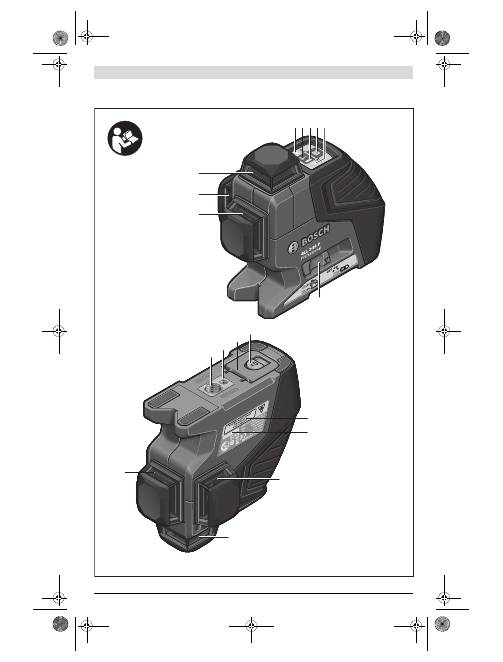
GLL 3-80 P
1
1
1
3 4 5 6
2
7
11
10
9
8
12
1
1
1
13
OBJ_BUCH-1046-002.book Page 3 Thursday, November 29, 2012 12:07 PM
1 619 929 L95 | (29.11.12)
Bosch Power Tools
4
|
30 mm
F E D C B A
OBJ_BUCH-1046-002.book Page 4 Thursday, November 29, 2012 12:07 PM
5
|
1 619 929 L95 | (29.11.12)
Bosch Power Tools
21
16
2
6
07 00
2
1
9
5
2
6
07
99
0 031
BT 350
0
6
01 015 B00
17
19
LR
2
0
6
01 0
69
100
22
18
14
14
1
6
08 M00 80K
15
BM 1
0
6
01 015 A00
BS 150
0
6
01 0
96
9
74
20
H G
OBJ_BUCH-1046-002.book Page 5 Thursday, November 29, 2012 12:07 PM
6
| Deutsch
1 619 929 L95 | (29.11.12)
Bosch Power Tools
Deutsch
Sicherheitshinweise
Linienlaser
Sämtliche Anweisungen sind zu lesen und
zu beachten, um mit dem Messwerkzeug ge-
fahrlos und sicher zu arbeiten. Machen Sie
Warnschilder am Messwerkzeug niemals
unkenntlich. BEWAHREN SIE DIESE ANWEI-
SUNGEN GUT AUF.
Vorsicht – wenn andere als die hier angegebenen Be-
dienungs- oder Justiereinrichtungen benutzt oder an-
dere Verfahrensweisen ausgeführt werden, kann dies
zu gefährlicher Strahlungsexposition führen.
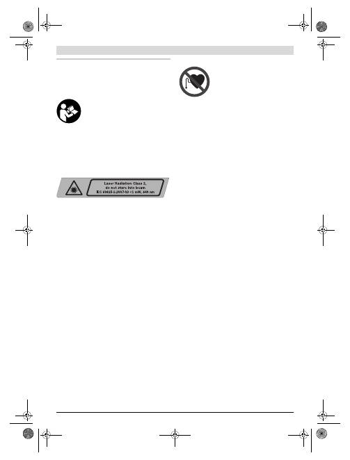
Das Messwerkzeug wird mit einem Warnschild ausge-
liefert (in der Darstellung des Messwerkzeugs auf der
Grafikseite mit Nummer 12 gekennzeichnet).
Ist der Text des Warnschildes nicht in Ihrer Landes-
sprache, dann überkleben Sie ihn vor der ersten Inbe-
triebnahme mit dem mitgelieferten Aufkleber in Ihrer
Landessprache.
Richten Sie den Laserstrahl nicht auf Personen oder
Tiere und blicken Sie nicht selbst in den Laserstrahl.
Dieses
M
esswerkzeug erzeugt Laserstrahlung der Laser-
klasse 2 ge
m
äß IEC 60825-1. Dadurch können
S
ie Perso-
nen blenden.
Verwenden Sie die Laser-Sichtbrille nicht als Schutz-
brille.
Die Laser-
S
ichtbrille dient zu
m
besseren Erkennen
des Laserstrahls, sie schützt jedoch nicht vor der Laser-
strahlung.
Verwenden Sie die Laser-Sichtbrille nicht als Sonnen-
brille oder im Straßenverkehr.
Die Laser-
S
ichtbrille bie-
tet keinen vollständigen UV-
S
chutz und ver
m
indert die
Farbwahrneh
m
ung.
Lassen Sie das Messwerkzeug von qualifiziertem Fach-
personal und nur mit Original-Ersatzteilen reparieren.
Da
m
it wird sichergestellt, dass die
S
icherheit des
M
ess-
werkzeuges erhalten bleibt.
Lassen Sie Kinder das Laser-Messwerkzeug nicht unbe-
aufsichtigt benutzen.
S
ie könnten unbeabsichtigt Perso-
nen blenden.
Arbeiten Sie mit dem Messwerkzeug nicht in explosi-
onsgefährdeter Umgebung, in der sich brennbare Flüs-
sigkeiten, Gase oder Stäube befinden.
I
m
M
esswerk-
zeug können Funken erzeugt werden, die den
S
taub oder
die Dä
m
pfe entzünden.
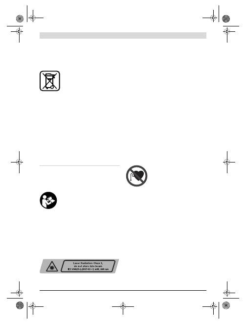
Laser-Zieltafel
Bringen Sie die Laser-Zieltafel 15 nicht
in die Nähe von Herzschrittmachern.
Durch die
M
agnete an der Laser-Zieltafel
wird ein Feld erzeugt, das die Funktion von
Herzschritt
m
achern beeinträchtigen kann.
Halten Sie die Laser-Zieltafel 15 fern von magneti-
schen Datenträgern und magnetisch empfindlichen
Geräten.
Durch die Wirkung der
M
agnete an der Laser-
Zieltafel kann es zu irreversiblen Datenverlusten ko
mm
en.
Produkt- und Leistungsbeschreibung
Bitte klappen
S
ie die Ausklappseite
m
it der Darstellung des
M
esswerkzeugs auf, und lassen
S
ie diese
S
eite aufgeklappt,
während
S
ie die Betriebsanleitung lesen.
Bestimmungsgemäßer Gebrauch
Das
M
esswerkzeug ist besti
mm
t zu
m
Er
m
itteln und Über-
prüfen von waagrechten und senkrechten Linien.
Geräuschinformation
Der A-bewertete
S
challdruckpegel des
S
ignaltons beträgt in
eine
m
M
eter Abstand 80 dB(A).
Halten Sie das Messwerkzeug nicht dicht ans Ohr!
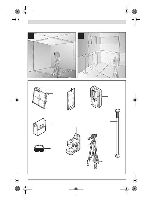
Abgebildete Komponenten
Die Nu
mm
erierung der abgebildeten Ko
m
ponenten bezieht
sich auf die Darstellung des
M
esswerkzeugs auf der Grafikseite.
1
Austrittsöffnung Laserstrahlung
2
Batteriewarnung
3
Taste Pulsfunktion
4
Anzeige Pulsfunktion
5
Betriebsarten-Taste
6
Anzeige Arbeiten ohne Nivellierauto
m
atik
7
Ein-/Ausschalter
8
S
tativaufnah
m
e 5/8"
9
S
tativaufnah
m
e 1/4"
10
Batteriefachdeckel
11
Arretierung des Batteriefachdeckels
12
Laser-Warnschild
13
S
eriennu
mm
er
14
M
agnete
15
Laser-Zieltafel
16
M
essplatte
m
it Fuß*
17
Lasere
m
pfänger*
18
S
chutztasche*
19
Universelle Halterung*
20
Teleskopstange*
21
Laser-
S
ichtbrille*
22
S
tativ*
* Abgebildetes oder beschriebenes Zubehör gehört nicht zum
Standard-Lieferumfang.
OBJ_BUCH-1046-002.book Page 6 Thursday, November 29, 2012 12:07 PM
Deutsch |
7
Bosch Power Tools
1 619 929 L95 | (29.11.12)
Technische Daten
Montage
Batterien einsetzen/wechseln
Für den Betrieb des
M
esswerkzeugs wird die Verwendung
von Alkali-
M
angan-Batterien e
m
pfohlen.
Zu
m
Öffnen des Batteriefachdeckels
10
schieben
S
ie die
Arretierung
11
in Pfeilrichtung und klappen den Batteriefach-
deckel auf.
S
etzen
S
ie die Batterien ein. Achten
S
ie dabei auf
die richtige Polung entsprechend der Darstellung auf der
Innenseite des Batteriefachdeckels.
Werden die Batterien schwach, ertönt ein ein
m
aliger
S
ignalton
von 5 s Dauer. Die Batteriewarnung
2
blinkt dauerhaft rot. Das
M
esswerkzeug kann noch weniger als 2 h betrieben werden.
S
ind die Batterien bei
m
Einschalten des
M
esswerkzeugs
schwach, ertönt der 5 s lange
S
ignalton direkt nach de
m
Ein-
schalten des
M
esswerkzeugs.
Ersetzen
S
ie i
mm
er alle Batterien gleichzeitig. Verwenden
S
ie
nur Batterien eines Herstellers und
m
it gleicher Kapazität.
Nehmen Sie die Batterien aus dem Messwerkzeug, wenn
Sie es längere Zeit nicht benutzen.
Die Batterien können
bei längerer Lagerung korrodieren und sich selbst entladen.
Betrieb
Inbetriebnahme
Beim Betrieb des Messwerkzeugs ertönen unter be-
stimmten Bedingungen laute Signaltöne. Halten Sie
deshalb das Messwerkzeug vom Ohr bzw. von anderen
Personen fern.
Der laute Ton kann das Gehör schädigen.
Schützen Sie das Messwerkzeug vor Nässe und direk-
ter Sonneneinstrahlung.
Setzen Sie das Messwerkzeug keinen extremen Tempe-
raturen oder Temperaturschwankungen aus.
Lassen
S
ie
es z.B. nicht längere Zeit i
m
Auto liegen. Lassen
S
ie das
M
esswerkzeug bei größeren Te
m
peraturschwankungen erst
auste
m
perieren, bevor
S
ie es in Betrieb neh
m
en. Bei extre-
m
en Te
m
peraturen oder Te
m
peraturschwankungen kann
die Präzision des
M
esswerkzeugs beeinträchtigt werden.
Vermeiden Sie heftige Stöße oder Stürze des Mess-
werkzeuges.
Nach starken äußeren Einwirkungen auf das
M
esswerkzeug sollten
S
ie vor de
m
Weiterarbeiten i
mm
er
eine Genauigkeitsüberprüfung durchführen (siehe „Nivel-
liergenauigkeit“).
Schalten Sie das Messwerkzeug aus, wenn Sie es trans-
portieren.
Bei
m
Ausschalten wird die Pendeleinheit ver-
riegelt, die sonst bei starken Bewegungen beschädigt wer-
den kann.
Ein-/Ausschalten
Zu
m
Einschalten
des
M
esswerkzeugs schieben
S
ie den
Ein-/Ausschalter
7
in die Position
„
on“
(für Arbeiten ohne
Nivellierauto
m
atik) oder in die Position
„
on“
(für Arbei-
ten
m
it Nivellierauto
m
atik). Das
M
esswerkzeug sendet so-
fort nach de
m
Einschalten Laserlinien aus den Austrittsöff-
nungen
1
.
Richten Sie den Laserstrahl nicht auf Personen oder
Tiere und blicken Sie nicht selbst in den Laserstrahl,
auch nicht aus größerer Entfernung.
Zu
m
Ausschalten
des
M
esswerkzeugs schieben
S
ie den
Ein-/Ausschalter
7
in die Position
„off“
. Bei
m
Ausschalten
wird die Pendeleinheit verriegelt.
Bei Überschreiten der höchstzulässigen Betriebste
m
peratur
von 40 °C erfolgt die Abschaltung zu
m
S
chutz der Laserdiode.
Nach de
m
Abkühlen ist das
M
esswerkzeug wieder betriebs-
bereit und kann erneut eingeschaltet werden.
Abschaltautomatik deaktivieren
Wird ca. 30
m
in lang keine Taste a
m
M
esswerkzeug gedrückt,
schaltet sich das
M
esswerkzeug zur
S
chonung der Batterien
auto
m
atisch ab.
U
m
das
M
esswerkzeug nach der auto
m
atischen Abschaltung
wieder einzuschalten, können
S
ie entweder den Ein-/Aus-
schalter
7
erst in Position
„off“
schieben und das
M
esswerk-
zeug dann wieder einschalten, oder
S
ie drücken ein
m
al die
Betriebsarten-Taste
5
oder die Taste Pulsfunktion
3
.
U
m
die Abschaltauto
m
atik zu deaktivieren, halten
S
ie (bei
eingeschaltete
m
M
esswerkzeug) die Betriebsarten-Taste
5
m
indestens 3 s lang gedrückt. Ist die Abschaltauto
m
atik de-
aktiviert, blinken die Laserstrahlen kurz zur Bestätigung.
Linienlaser
GLL 3-80 P
S
achnu
mm
er
3 601 K63 300
Arbeitsbereich
1)
–
S
tandard
–
m
it Pulsfunktion
–
m
it Lasere
m
pfänger
20
m
15
m
5 –80
m
Nivelliergenauigkeit
±0,2
mm
/
m
S
elbstnivellierbereich typisch
±4°
Nivellierzeit typisch
<4 s
Betriebste
m
peratur
–10 °C ... +40 °C
Lagerte
m
peratur
–20 °C ... +70 °C
R
elative Luftfeuchte
m
ax.
90 %
Laserklasse
2
Lasertyp
640 n
m
, <1
m
W
C
6
1
kürzeste I
m
pulsdauer
1/1600 s
S
tativaufnah
m
e
1/4", 5/8"
Batterien
4 x 1,5 V L
R
06 (AA)
Betriebsdauer
–
m
it 3 Laserebenen
–
m
it 2 Laserebenen
–
m
it 1 Laserebene
5 h
9 h
18 h
Gewicht entsprechend
EPTA-Procedure 01/2003
0,75 kg
M
aße (Länge x Breite x Höhe)
159 x 75 x 141
mm
S
chutzart
IP 54 (staub- und spritz-
wassergeschützt)
1) Der Arbeitsbereich kann durch ungünstige U
m
gebungsbedingungen
(z.B. direkte
S
onneneinstrahlung) verringert werden.
Zur eindeutigen Identifizierung Ihres
M
esswerkzeugs dient die
S
erien-
nu
mm
er
13
auf de
m
Typenschild.
OBJ_BUCH-1046-002.book Page 7 Thursday, November 29, 2012 12:07 PM
8
| Deutsch
1 619 929 L95 | (29.11.12)
Bosch Power Tools
Lassen Sie das eingeschaltete Messwerkzeug nicht un-
beaufsichtigt und schalten Sie das Messwerkzeug nach
Gebrauch ab.
Andere Personen könnten vo
m
Laserstrahl
geblendet werden.
U
m
die auto
m
atische Abschaltung zu aktivieren, schalten
S
ie
das
M
esswerkzeug aus und wieder ein, oder
S
ie halten statt-
dessen die Betriebsarten-Taste
5
m
indestens 3 s lang ge-
drückt.
Signalton deaktivieren
Nach de
m
Einschalten des
M
esswerkzeugs ist der
S
ignalton
i
mm
er aktiviert.
Zu
m
Deaktivieren bzw. Aktivieren des
S
ignaltons drücken
S
ie
gleichzeitig die Betriebsarten-Taste
5
und die Taste Pulsfunk-
tion
3
und halten sie
m
indestens 3 s gedrückt.
S
owohl bei
m
Aktivieren als auch bei
m
Deaktivieren ertönen
drei kurze
S
ignaltöne zur Bestätigung.
Betriebsarten
Das
M
esswerkzeug verfügt über
m
ehrere Betriebsarten, zwi-
schen denen
S
ie jederzeit wechseln können:
– Erzeugen einer waagrechten Laserebene,
– Erzeugen einer senkrechten Laserebene,
– Erzeugen von zwei senkrechten Laserebenen,
– Erzeugen einer waagrechten Laserebene sowie von zwei
senkrechten Laserebenen.
Nach de
m
Einschalten erzeugt das
M
esswerkzeug eine waag-
rechte Laserebene. U
m
die Betriebsart zu wechseln, drücken
S
ie die Betriebsarten-Taste
5
.
Alle Betriebsarten können sowohl
m
it als auch ohne Nivellier-
auto
m
atik gewählt werden.
Pulsfunktion
Für das Arbeiten
m
it de
m
Lasere
m
pfänger
17
m
uss – unab-
hängig von der gewählten Betriebsart – die Pulsfunktion akti-
viert werden.
In der Pulsfunktion blinken die Laserlinien
m
it sehr hoher Fre-
quenz und werden dadurch für den Lasere
m
pfänger
17
auf-
findbar.
Zu
m
Einschalten der Pulsfunktion drücken
S
ie die Taste
3
.
Bei eingeschalteter Pulsfunktion leuchtet die Anzeige
4
grün.
Für das
m
enschliche Auge ist die
S
ichtbarkeit der Laserlinien
bei eingeschalteter Pulsfunktion verringert. Für Arbeiten
ohne Lasere
m
pfänger schalten
S
ie deshalb die Pulsfunktion
durch erneutes Drücken der Taste
3
aus. Bei ausgeschalteter
Pulsfunktion erlischt die Anzeige
4
.
Nivellierautomatik
Arbeiten mit Nivellierautomatik
S
tellen
S
ie das
M
esswerkzeug auf eine waagerechte, feste
Unterlage, befestigen
S
ie es auf der Halterung
19
oder de
m
S
tativ
22
.
S
chieben
S
ie für Arbeiten
m
it Nivellierauto
m
atik den Ein-/Aus-
schalter
7
in Position
„
on“
.
Die Nivellierauto
m
atik gleicht Unebenheiten innerhalb des
S
elbstnivellierbereiches von ±4° auto
m
atisch aus. Die Nivel-
lierung ist abgeschlossen, sobald sich die Laserlinien nicht
m
ehr bewegen.
Ist die auto
m
atische Nivellierung nicht
m
öglich, z.B. weil die
S
tandfläche des
M
esswerkzeugs
m
ehr als 4° von der Waage-
rechten abweicht, beginnen die Laserlinien in schnelle
m
Takt
zu blinken. Bei aktivierte
m
S
ignalton ertönt für
m
axi
m
al 30 s
ein
S
ignalton in schnelle
m
Takt. Innerhalb von 10 s nach de
m
Einschalten ist dieser Alar
m
deaktiviert, u
m
das Einrichten
des
M
esswerkzeugs zu er
m
öglichen.
S
tellen
S
ie das
M
esswerkzeug waagerecht auf und warten
S
ie die
S
elbstnivellierung ab.
S
obald sich das
M
esswerkzeug
innerhalb des
S
elbstnivellierbereiches von ±4° befindet,
leuchten die Laserstrahlen dauerhaft und der
S
ignalton wird
abgeschaltet.
Bei Erschütterungen oder Lageänderungen während des
Betriebs wird das
M
esswerkzeug auto
m
atisch wieder einni-
velliert. Überprüfen
S
ie nach einer erneuten Nivellierung die
Position der waagrechten bzw. senkrechten Laserlinie in
Bezug auf
R
eferenzpunkte, u
m
Fehler zu ver
m
eiden.
Arbeiten ohne Nivellierautomatik
S
chieben
S
ie für Arbeiten ohne Nivellierauto
m
atik den
Ein-/Ausschalter
7
in Position
„
on“
. Bei ausgeschalteter
Nivellierauto
m
atik leuchtet die Anzeige
6
rot und für 30 s
blinken die Laserlinien in langsa
m
e
m
Takt.
Bei abgeschalteter Nivellierauto
m
atik können
S
ie das
M
ess-
werkzeug frei in der Hand halten oder auf eine geneigte Unter-
lage stellen. Die Laserlinien verlaufen nicht
m
ehr zwingend
senkrecht zueinander.
Nivelliergenauigkeit
Genauigkeitseinflüsse
Den größten Einfluss übt die U
m
gebungste
m
peratur aus.
Besonders vo
m
Boden nach oben verlaufende Te
m
peratur-
unterschiede können den Laserstrahl ablenken.
Da die Te
m
peraturschichtung in Bodennähe a
m
größten ist,
sollten
S
ie das
M
esswerkzeug ab einer
M
essstrecke von 20
m
i
mm
er auf eine
m
S
tativ
m
ontieren.
S
tellen
S
ie das
M
esswerk-
zeug außerde
m
nach
M
öglichkeit in der
M
itte der Arbeitsflä-
che auf.
Neben äußeren Einflüssen können auch gerätespezifische
Einflüsse (wie z.B.
S
türze oder heftige
S
töße) zu Abweichun-
gen führen. Überprüfen
S
ie deshalb vor jede
m
Arbeitsbeginn
die Genauigkeit des
M
esswerkzeugs.
Überprüfen
S
ie jeweils zuerst die Nivelliergenauigkeit der
waagrechten Laserlinie und danach die Nivelliergenauigkeit
der senkrechten Laserlinien.
S
ollte das
M
esswerkzeug bei einer der Prüfungen die
m
axi
m
ale
Abweichung überschreiten, dann lassen
S
ie es von eine
m
Bosch-Kundendienst reparieren.
OBJ_BUCH-1046-002.book Page 8 Thursday, November 29, 2012 12:07 PM
Deutsch |
9
Bosch Power Tools
1 619 929 L95 | (29.11.12)
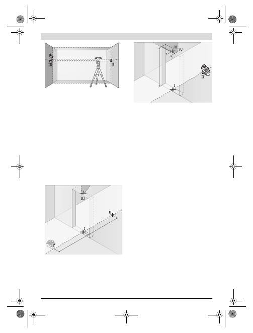
Waagerechte Nivelliergenauigkeit der Querachse
überprüfen
Für die Überprüfung benötigen
S
ie eine freie
M
essstrecke von
5
m
auf feste
m
Grund zwischen zwei Wänden A und B.
–
M
ontieren
S
ie das
M
esswerkzeug nahe der Wand A auf
eine
m
S
tativ oder stellen
S
ie es auf festen, ebenen Unter-
grund.
S
chalten
S
ie das
M
esswerkzeug i
m
Betrieb
m
it
Nivellierauto
m
atik ein. Wählen
S
ie die Betriebsart, in der
eine waagrechte Laserebene sowie eine senkrechte Laser-
ebene frontal vor de
m
M
esswerkzeug erzeugt werden.
–
R
ichten
S
ie den Laser auf die nahe Wand A und lassen
S
ie
das
M
esswerkzeug einnivellieren.
M
arkieren
S
ie die
M
itte
des Punktes, an de
m
sich die Laserlinien an der Wand A
kreuzen (Punkt
I
).
– Drehen
S
ie das
M
esswerkzeug u
m
180°, lassen
S
ie es ein-
nivellieren und
m
arkieren
S
ie den Kreuzungspunkt der
Laserlinien an der gegenüberliegenden Wand B (Punkt
II
).
– Platzieren
S
ie das
M
esswerkzeug – ohne es zu drehen –
nahe der Wand B, schalten
S
ie es ein und lassen
S
ie es ein-
nivellieren.
–
R
ichten
S
ie das
M
esswerkzeug in der Höhe so aus (
m
ithilfe
des
S
tativs oder gegebenenfalls durch Unterlegen), dass
der Kreuzungspunkt der Laserlinien genau den zuvor
m
ar-
kierten Punkt
II
auf der Wand B trifft.
– Drehen
S
ie das
M
esswerkzeug u
m
180°, ohne die Höhe zu
verändern.
R
ichten
S
ie es so auf die Wand A, dass die
senkrechte Laserlinie durch den bereits
m
arkierten
Punkt
I
läuft. Lassen
S
ie das
M
esswerkzeug einnivellieren
und
m
arkieren
S
ie den Kreuzungspunkt der Laserlinien auf
der Wand A (Punkt
III
).
– Die Differenz
d
der beiden
m
arkierten Punkte
I
und
III
auf
der Wand A ergibt die tatsächliche Höhenabweichung des
M
esswerkzeugs entlang der Querachse.
Auf der
M
essstrecke von 2 x 5
m
= 10
m
beträgt die
m
axi
m
al
zulässige Abweichung:
10
m
x ±0,2
mm
/
m
= ±2
mm
.
Die Differenz
d
zwischen den Punkten
I
und
III
darf folglich
höchstens 2
mm
betragen.
Nivelliergenauigkeit der senkrechten Linien überprüfen
Für die Überprüfung benötigen
S
ie eine Türöffnung, bei der
(auf feste
m
Grund) auf jeder
S
eite der Tür
m
indestens 2,5
m
Platz sind.
–
S
tellen
S
ie das
M
esswerkzeug in 2,5
m
Entfernung von der
Türöffnung auf feste
m
, ebene
m
Grund auf (nicht auf eine
m
S
tativ).
S
chalten
S
ie das
M
esswerkzeug i
m
Betrieb
m
it
Nivellierauto
m
atik ein. Wählen
S
ie eine Betriebsart, in der
eine senkrechte Laserebene frontal vor de
m
M
esswerk-
zeug erzeugt wird.
–
M
arkieren
S
ie die
M
itte der senkrechten Laserlinie a
m
Bo-
den der Türöffnung (Punkt
I
), in 5
m
Entfernung auf der an-
deren
S
eite der Türöffnung (Punkt
II
) sowie a
m
oberen
R
and der Türöffnung (Punkt
III
).
A
B
5 m
A
B
180°
A
B
A
B
d
d
180°
2,5 m
2,5 m
OBJ_BUCH-1046-002.book Page 9 Thursday, November 29, 2012 12:07 PM
10
| Deutsch
1 619 929 L95 | (29.11.12)
Bosch Power Tools
– Drehen
S
ie das
M
esswerkzeug u
m
180° und stellen
S
ie es
auf der anderen
S
eite der Türöffnung direkt hinter den
Punkt
II
. Lassen
S
ie das
M
esswerkzeug einnivellieren und
richten
S
ie die senkrechte Laserlinie so aus, dass ihre
M
it-
te genau durch die Punkte
I
und
II
verläuft.
–
M
arkieren
S
ie die
M
itte der Laserlinie a
m
oberen
R
and der
Türöffnung als Punkt
IV
.
– Die Differenz
d
der beiden
m
arkierten Punkte
III
und
IV
ergibt die tatsächliche Abweichung des
M
esswerkzeugs
von der
S
enkrechten.
–
M
essen
S
ie die Höhe der Türöffnung.
Wiederholen
S
ie den
M
essvorgang für die zweite senkrechte
Laserebene. Wählen
S
ie dazu eine Betriebsart, in der eine
senkrechte Laserebene seitlich neben de
m
M
esswerkzeug
erzeugt wird, und drehen
S
ie das
M
esswerkzeug vor de
m
Beginn des
M
essvorganges u
m
90°.
Die
m
axi
m
ale zulässige Abweichung berechnen
S
ie wie folgt:
doppelte Höhe der Türöffnung x 0,2
mm
/
m
Beispiel: Bei einer Höhe der Türöffnung von 2
m
darf die
m
axi-
m
ale Abweichung
2 x 2
m
x ±0,2
mm
/
m
= ±0,8
mm
betragen. Die Punkte
III
und
IV
dürfen bei jeder der beiden
M
essungen folglich höchs-
tens 0,8
mm
auseinander liegen.
Arbeitshinweise
Verwenden Sie immer nur die Mitte der Laserlinie zum
Markieren.
Die Breite der Laserlinie ändert sich
m
it der
Entfernung.
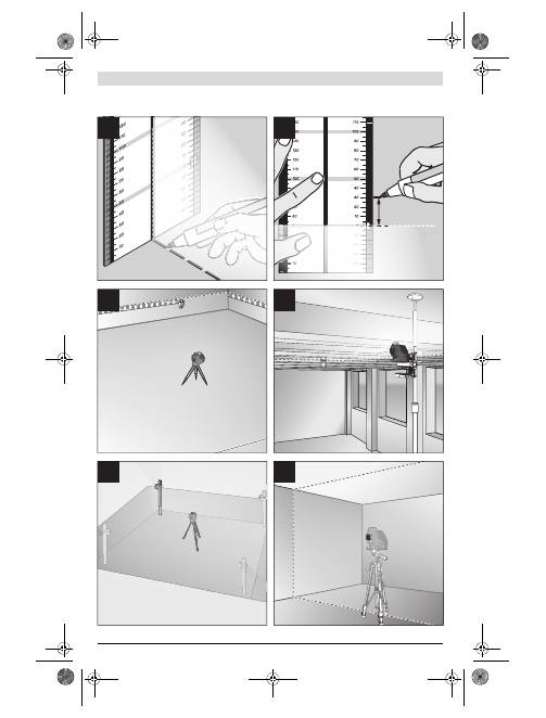
Arbeiten mit der Laser-Zieltafel
Die Laser-Zieltafel
15
verbessert die
S
ichtbarkeit des Laser-
strahls bei ungünstigen Bedingungen und größeren Entfer-
nungen.
Die reflektierende Hälfte der Laser-Zieltafel
15
verbessert die
S
ichtbarkeit der Laserlinie, durch die transparente Hälfte ist
die Laserlinie auch von der
R
ückseite der Laser-Zieltafel er-
kennbar.
Arbeiten mit dem Stativ (Zubehör)
Ein
S
tativ bietet eine stabile, höheneinstellbare
M
essunter-
lage.
S
etzen
S
ie das
M
esswerkzeug
m
it der 1/4"-
S
tativauf-
nah
m
e
9
auf das Gewinde des
S
tativs
22
oder eines handels-
üblichen Fotostativs. Für die Befestigung auf eine
m
handels-
üblichen Baustativ benutzen
S
ie die 5/8"-
S
tativaufnah
m
e
8
.
S
chrauben
S
ie das
M
esswerkzeug
m
it der Feststellschraube
des
S
tativs fest.
Befestigen mit der universellen Halterung (Zubehör)
(siehe Bild D)
M
ithilfe der universellen Halterung
19
können
S
ie das
M
ess-
werkzeug z.B. an senkrechten Flächen,
R
ohren oder
m
agneti-
sierbaren
M
aterialien befestigen. Die universelle Halterung ist
ebenso als Bodenstativ geeignet und erleichtert die Höhen-
ausrichtung des
M
esswerkzeugs.
Arbeiten mit der Messplatte (Zubehör)
(siehe Bilder A–B)
M
ithilfe der
M
essplatte
16
können
S
ie die Laser
m
arkierung
auf den Boden bzw. die Laserhöhe auf eine Wand übertragen.
M
it de
m
Nullfeld und der
S
kala können
S
ie den Versatz zur ge-
wünschten Höhe
m
essen und an anderer
S
telle wieder antra-
gen. Da
m
it entfällt das exakte Einstellen des
M
esswerkzeugs
auf die zu übertragende Höhe.
Die
M
essplatte
16
hat eine
R
eflexbeschichtung, die die
S
icht-
barkeit des Laserstrahls in größerer Entfernung bzw. bei star-
ker
S
onnenstrahlung verbessert. Die Helligkeitsverstärkung
ist nur zu erkennen, wenn
S
ie parallel zu
m
Laserstrahl auf die
M
essplatte blicken.
Arbeiten mit Laserempfänger (Zubehör) (siehe Bild D)
Bei ungünstigen Lichtverhältnissen (helle U
m
gebung,
direkte
S
onneneinstrahlung) und auf größere Entfernungen
verwenden
S
ie zu
m
besseren Auffinden der Laserlinien den
Lasere
m
pfänger
17
.
S
chalten
S
ie bei
m
Arbeiten
m
it de
m
Lasere
m
pfänger die Pulsfunktion ein (siehe „Pulsfunktion“,
S
eite 8).
Laser-Sichtbrille (Zubehör)
Die Laser-
S
ichtbrille filtert das U
m
gebungslicht aus. Dadurch
erscheint das rote Licht des Lasers für das Auge heller.
Verwenden Sie die Laser-Sichtbrille nicht als Schutz-
brille.
Die Laser-
S
ichtbrille dient zu
m
besseren Erkennen
des Laserstrahls, sie schützt jedoch nicht vor der Laser-
strahlung.
Verwenden Sie die Laser-Sichtbrille nicht als Sonnen-
brille oder im Straßenverkehr.
Die Laser-
S
ichtbrille bie-
tet keinen vollständigen UV-
S
chutz und ver
m
indert die
Farbwahrneh
m
ung.
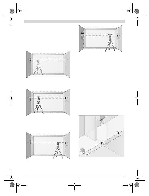
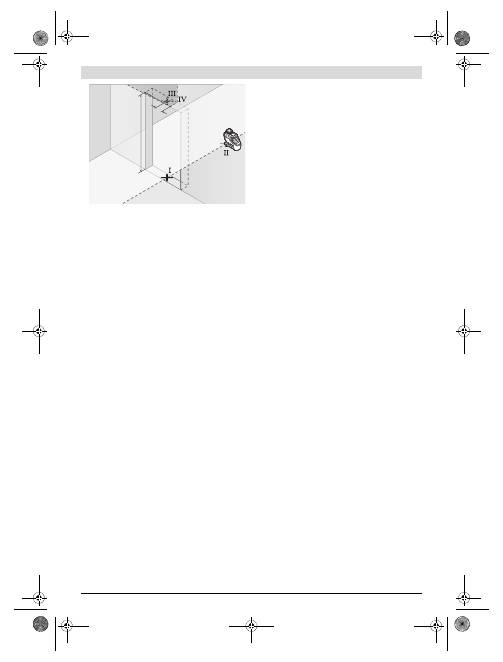
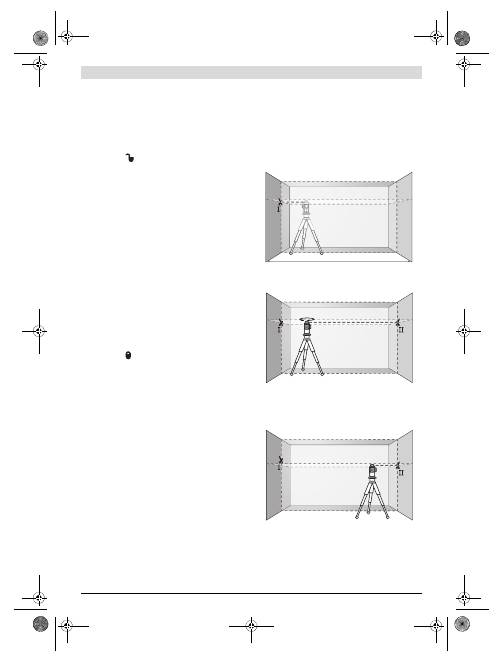
Arbeitsbeispiele (siehe Bilder C–H)
Beispiele für Anwendungs
m
öglichkeiten des
M
esswerkzeugs
finden
S
ie auf den Grafikseiten.
Wartung und Service
Wartung und Reinigung
Lagern und transportieren
S
ie das
M
esswerkzeug nur in der
m
itgelieferten
S
chutztasche oder de
m
Koffer.
Halten
S
ie das
M
esswerkzeug stets sauber.
Tauchen
S
ie das
M
esswerkzeug nicht ins Wasser oder andere
Flüssigkeiten.
Wischen
S
ie Versch
m
utzungen
m
it eine
m
feuchten, weichen
Tuch ab. Verwenden
S
ie keine
R
einigungs- oder Löse
m
ittel.
R
einigen
S
ie insbesondere die Flächen an der Austrittsöff-
nung des Lasers regel
m
äßig und achten
S
ie dabei auf Fusseln.
2 m
d
OBJ_BUCH-1046-002.book Page 10 Thursday, November 29, 2012 12:07 PM
English |
11
Bosch Power Tools
1 619 929 L95 | (29.11.12)
S
ollte das
M
esswerkzeug trotz sorgfältiger Herstellungs-
und Prüfverfahren ein
m
al ausfallen, ist die
R
eparatur von
einer autorisierten Kundendienststelle für Bosch-Elektro-
werkzeuge ausführen zu lassen. Öffnen
S
ie das
M
esswerk-
zeug nicht selbst.
Geben
S
ie bei allen
R
ückfragen und Ersatzteilbestellungen
bitte unbedingt die 10-stellige
S
achnu
mm
er laut Typenschild
des
M
esswerkzeugs an.
S
enden
S
ie i
m
R
eparaturfall das
M
esswerkzeug in der
S
chutz-
tasche
18
ein.
Kundendienst und Anwendungsberatung
Der Kundendienst beantwortet Ihre Fragen zu
R
eparatur und
Wartung Ihres Produkts sowie zu Ersatzteilen. Explosions-
zeichnungen und Infor
m
ationen zu Ersatzteilen finden
S
ie
auch unter:
www.bosch-pt.com
Das Bosch-Anwendungsberatungs-Tea
m
hilft Ihnen gerne
bei Fragen zu unseren Produkten und deren Zubehör.
www.powertool-portal.de
, das Internetportal für Hand-
werker und Hei
m
werker.
Deutschland
R
obert Bosch G
m
bH
S
ervicezentru
m
Elektrowerkzeuge
Zur Luhne 2
37589 Kalefeld – Willershausen
Unter www.bosch-pt.co
m
können
S
ie online Ersatzteile
bestellen oder
R
eparaturen an
m
elden.
Kundendienst: Tel.: (0711) 40040480
Fax: (0711) 40040481
E-
M
ail:
S
ervicezentru
m
.Elektrowerkzeuge@de.bosch.co
m
Anwendungsberatung: Tel.: (0711) 40040480
Fax: (0711) 40040482
E-
M
ail: Anwendungsberatung.pt@de.bosch.co
m
Österreich
Tel.: (01) 797222010
Fax: (01) 797222011
E-
M
ail: service.elektrowerkzeuge@at.bosch.co
m
Schweiz
Tel.: (044) 8471511
Fax: (044) 8471551
E-
M
ail: Aftersales.
S
ervice@de.bosch.co
m
Luxemburg
Tel.: +32 2 588 0589
Fax: +32 2 588 0595
E-
M
ail: outillage.gereedschap@be.bosch.co
m
Entsorgung
M
esswerkzeuge, Zubehör und Verpackungen sollen einer
u
m
weltgerechten Wiederverwertung zugeführt werden.
Werfen
S
ie
M
esswerkzeuge und Akkus/Batterien nicht in den
Haus
m
üll!
Nur für EU-Länder:
Ge
m
äß der europäischen
R
ichtlinie
2002/96/EG
m
üssen nicht
m
ehr gebrauchs-
fähige
M
esswerkzeuge und ge
m
äß der euro-
päischen
R
ichtlinie 2006/66/EG
m
üssen de-
fekte oder verbrauchte Akkus/Batterien
getrennt gesa
mm
elt und einer u
m
weltgerech-
ten Wiederverwendung zugeführt werden.
Nicht
m
ehr gebrauchsfähige Akkus/Batterien können direkt
abgegeben werden bei:
Deutschland
R
ecyclingzentru
m
Elektrowerkzeuge
Osteroder Landstraße 3
37589 Kalefeld
Schweiz
Batrec AG
3752 Wi
mm
is BE
Änderungen vorbehalten.
English
Safety Notes
Line laser
Working safely with the measuring tool is
possible only when the operating and safety
information are read completely and the in-
structions contained therein are strictly fol-
lowed. Never make warning labels on the
measuring tool unrecognisable. SAVE
THESE INSTRUCTIONS.
Caution – The use of other operating or adjusting
equipment or the application of other processing meth-
ods than those mentioned here, can lead to dangerous
radiation exposure.
The measuring tool is provided with a warning label
(marked with number 12 in the representation of the
measuring tool on the graphics page).
If the text of the warning label is not in your national
language, stick the provided warning label in your
national language over it before operating for the first
time.
Do not direct the laser beam at persons or animals and
do not stare into the laser beam yourself.
This
m
easur-
ing tool produces laser class 2 laser radiation according to
IEC 60825-1. This can lead to persons being blinded.
Do not use the laser viewing glasses as safety goggles.
The laser viewing glasses are used for i
m
proved visualisa-
tion of the laser bea
m
, but they do not protect against laser
radiation.
OBJ_BUCH-1046-002.book Page 11 Thursday, November 29, 2012 12:07 PM
12
| English
1 619 929 L95 | (29.11.12)
Bosch Power Tools
Do not use the laser viewing glasses as sun glasses or in
traffic.
The laser viewing glasses do not afford co
m
plete
UV protection and reduce colour perception.
Have the measuring tool repaired only through quali-
fied specialists using original spare parts.
This ensures
that the safety of the
m
easuring tool is
m
aintained.
Do not allow children to use the laser measuring tool
without supervision.
They could unintentionally blind
other persons or the
m
selves.
Do not operate the measuring tool in explosive environ-
ments, such as in the presence of flammable liquids,
gases or dusts.
S
parks can be created in the
m
easuring
tool which
m
ay ignite the dust or fu
m
es.
Laser target plate
Keep the laser target plate 15 away from
cardiac pacemakers.
The
m
agnets on the
laser target plate generate a field that can
i
m
pair the function of cardiac pace
m
akers.
Keep the laser target plate 15 away from magnetic data
medium and magnetically-sensitive equipment.
The
effect of the
m
agnets on the laser target plate can lead to
irreversible data loss.
Product Description and
Specifications
Please unfold the fold-out page with the representation of the
m
easuring tool and leave it unfolded while reading the operat-
ing instructions.
Intended Use
The
m
easuring tool is intended for deter
m
ining and checking
horizontal and vertical lines.
Noise Information
The A-weighted sound pressure level of the audio signal at
one
m
eter distance is 80 dB(A).
Do not hold the measuring tool close to your ear!
Product Features
The nu
m
bering of the product features shown refers to the
illustration of the
m
easuring tool on the graphic page.
1
Exit opening for laser bea
m
2
Battery low indicator
3
Pulse-function button
4
Pulse-function indicator
5
Operating
m
ode button
6
Working without auto
m
atic levelling indicator
7
On/Off switch
8
Tripod
m
ount 5/8"
9
Tripod
m
ount 1/4"
10
Battery lid
11
Latch of battery lid
12
Laser warning label
13
S
erial nu
m
ber
14
M
agnets
15
Laser target plate
16
M
easuring plate with stand*
17
Laser receiver*
18
Protective pouch*
19
Universal holder*
20
Telescopic rod*
21
Laser viewing glasses*
22
Tripod*
* The accessories illustrated or described are not included as
standard delivery.
Technical Data
Line laser
GLL 3-80 P
Article nu
m
ber
3 601 K63 300
Working range
1)
–
S
tandard
– With pulse function
– With laser receiver
20
m
15
m
5 –80
m
Levelling Accuracy
±0.2
mm
/
m
S
elf-levelling range, typically
±4°
Levelling duration, typically
<4 s
Operating te
m
perature
–10 °C ... +40 °C
S
torage te
m
perature
–20 °C ... +70 °C
R
elative air hu
m
idity,
m
ax.
90 %
Laser class
2
Laser type
640 n
m
, <1
m
W
C
6
1
S
hortest pulse duration
1/1600 s
Tripod
m
ount
1/4", 5/8"
Batteries
4 x 1.5 V L
R
06 (AA)
Operating duration
– With 3 laser planes
– With 2 laser planes
– With 1 laser plane
5 h
9 h
18 h
Weight according to
EPTA-Procedure 01/2003
0.75 kg
Di
m
ensions
(length x width x height)
159 x 75 x 141
mm
Degree of protection
IP 54 (dust and splash
water protected)
1) The working range can be decreased by unfavourable environ
m
ental
conditions (e.g. direct sun irradiation).
The
m
easuring tool can be clearly identified with the serial nu
m
ber
13
on the type plate.
OBJ_BUCH-1046-002.book Page 12 Thursday, November 29, 2012 12:07 PM
English |
13
Bosch Power Tools
1 619 929 L95 | (29.11.12)
Assembly
Inserting/Replacing the Battery
Alkali-
m
anganese batteries are reco
mm
ended for the
m
eas-
uring tool.
To open the battery lid
10
, slide the latch
11
in the direction
of the arrow and fold the battery lid up. Insert the batteries.
When inserting, pay attention to the correct polarity accord-
ing to the representation on the inside of the battery lid.
When the batteries beco
m
e weak, a single 5 s audio signal will
sound. The battery low indicator
2
continuously flashes red.
The
m
easuring tool can be operated for less then 2 h.
If the batteries are weak when switching on the
m
easuring
tool, the 5 s audio signal will sound directly after switching on
the
m
easuring tool.
Always replace all batteries at the sa
m
e ti
m
e. Only use batter-
ies fro
m
one brand and with the identical capacity.
Remove the batteries from the measuring tool when
not using it for extended periods.
When storing for ex-
tended periods, the batteries can corrode and discharge
the
m
selves.
Operation
Initial Operation
Loud audio signals will sound under certain conditions
while operating the measuring tool. Therefore, keep
the measuring tool away from your ear or other per-
sons.
The loud audio signal can cause hearing da
m
age.
Protect the measuring tool against moisture and direct
sun light.
Do not subject the measuring tool to extreme tempera-
tures or variations in temperature.
As an exa
m
ple, do
not leave it in vehicles for long ti
m
e. In case of large varia-
tions in te
m
perature, allow the
m
easuring tool to adjust to
the a
m
bient te
m
perature before putting it into operation.
In case of extre
m
e te
m
peratures or variations in te
m
pera-
ture, the accuracy of the
m
easuring tool can be i
m
paired.
Avoid heavy impact or falling of the measuring tool.
Af-
ter heavy exterior i
m
pact on the
m
easuring tool, an accura-
cy check should always be carried out before continuing to
work (see “Levelling Accuracy”).
Switch the measuring tool off during transport.
When
switching off, the levelling unit, which can be da
m
aged in
case of intense
m
ove
m
ent, is locked.
Switching On and Off
To
switch on
the
m
easuring tool, slide the On/Off switch
7
to
the
“
on”
position (when working without auto
m
atic level-
ling) or to the
“
on”
position (when working with auto
m
at-
ic levelling). I
mm
ediately after switching on, the
m
easuring
tool sends laser bea
m
s out of the exit openings
1
.
Do not point the laser beam at persons or animals and
do not look into the laser beam yourself, not even from
a large distance.
To
switch off
the
m
easuring tool, slide the On/Off switch
7
to
the
“off”
position. When switching off, the levelling unit is
locked.
When exceeding the
m
axi
m
u
m
per
m
itted operating te
m
pera-
ture of 40 °C, the
m
easuring tool switches off to protect the
laser diode. After cooling down, the
m
easuring tool is ready
for operation and can be switched on again.
Deactivating the Automatic Shut-off
When no button on the
m
easuring tool is pressed for approx.
30
m
inutes, the
m
easuring tool auto
m
atically switches off to
save the batteries.
To switch on the
m
easuring tool after auto
m
atic shut-off, either
slide the On/Off switch
7
to the
“off”
position and then switch
the
m
easuring tool on again or press the operating
m
ode button
5
once or press the pulse-function button
3
once.
To deactivate the auto
m
atic shut-off, keep the operating
m
ode button
5
pressed for at least 3 s (while the
m
easuring
tool is switched on). Deactivation of the auto
m
atic shut-off is
confir
m
ed by brief flashing of the laser bea
m
s.
Do not leave the switched on measuring tool unattend-
ed and switch the measuring tool off after use.
Other
persons could be blinded by the laser bea
m
.
To activate the auto
m
atic shut-off, switch the
m
easuring tool
off and then on again or press and hold the operating
m
ode
button
5
for at least 3 s.
Deactivating the Signal Tone
After the
m
easuring tool has been switched on, the audio sig-
nal is always activated.
To deactivate/activate the audio signal, press and hold the
operating
m
ode button
5
and the pulse-function button
3
at
the sa
m
e ti
m
e for at least 3 s.
The audio signal activation and deactivation are both con-
fir
m
ed by three short beeps.
Operating Modes
The
m
easuring tool has several operating
m
odes between
which you can switch at any ti
m
e. These are for:
– Generating a horizontal laser plane,
– Generating a vertical laser plane,
– Generating two vertical laser planes,
– Generating a horizontal laser plane as well as two vertical
laser planes.
After switching on, the
m
easuring tool generates a horizontal
laser plane. To change the operating
m
ode, press the operat-
ing
m
ode button
5
.
All operating
m
odes can be selected both with and without
auto
m
atic levelling.
Pulse Function
When working with the laser receiver
17
, the pulse function
m
ust be activated, – independent of the selected operating
m
ode.
In pulse function, the laser lines flash at very high frequency
and thus beco
m
e detectable by the laser receiver
17
.
To switch on the pulse function, press button
3
. When the
pulse function is switched on, the pulse-function indicator
4
lights up green.
When the pulse function is switched on, the visibility of the
laser lines is reduced for the hu
m
an eye. Therefore, shut off
the pulse function by pushing button
3
again when working
OBJ_BUCH-1046-002.book Page 13 Thursday, November 29, 2012 12:07 PM
14
| English
1 619 929 L95 | (29.11.12)
Bosch Power Tools
without laser receiver. When the pulse function is switched
off, the pulse-function indicator
4
is deactivated.
Automatic Levelling
Working with Automatic Levelling
Position the
m
easuring tool on a level and fir
m
support, attach
it to the holder
19
or to the tripod
22
.
When working with auto
m
atic levelling, push the On/Off
switch
7
to the
“
on”
position.
After switching on, the levelling function auto
m
atically co
m
-
pensates irregularities within the self-levelling range of ±4°.
The levelling is finished as soon as the laser bea
m
s do not
m
ove any
m
ore.
If auto
m
atic levelling is not possible, e.g. because the surface
on which the
m
easuring tool stands deviates by
m
ore than 4°
fro
m
the horizontal plane, the laser lines begin to flash rapid-
ly. When the audio signal is activated, a fast-beat signal
sounds for 30 s (
m
axi
m
u
m
). This alar
m
is deactivated within
10 s after switching on, in order to allow adjust
m
ent of the
m
easuring tool.
S
et up the
m
easuring tool in level position and wait for the
self-levelling to take place. As soon as the
m
easuring tool is
within the self-levelling range of ±4°, all laser bea
m
s light up
continuously and the audio signal is switched off.
In case of ground vibrations or position changes during opera-
tion, the
m
easuring tool is auto
m
atically levelled in again. To
avoid errors, check the position of the horizontal and vertical la-
ser line with regard to the reference points upon re-levelling.
Working without Automatic Levelling
For working without auto
m
atic levelling, slide the On/Off
switch
7
to the
“ on”
position. When auto
m
atic levelling is
switched off, indicator
6
lights up red and for the first 30 s la-
ser bea
m
s flash slowly.
When auto
m
atic levelling is switched off, you can hold the
m
easuring tool freely in your hand or place it on an inclinded
surface. The laser lines no longer necessarily run vertical to
each other.
Levelling Accuracy
Influences on Accuracy
The a
m
bient te
m
perature has the greatest influence. Espe-
cially te
m
perature differences occurring fro
m
the ground up-
ward can divert the laser bea
m
.
Because the largest difference in te
m
perature layers is close to
the ground, the
m
easuring tool should always be
m
ounted on a
tripod when
m
easuring distances exceeding 20
m
. If possible,
also set up the
m
easuring tool in the centre of the work area.
Apart fro
m
exterior influences, device-specific influences
(such as heavy i
m
pact or falling down) can lead to deviations.
Therefore, check the accuracy of the
m
easuring tool each
ti
m
e before starting your work.
Firstly, check the levelling accuracy of the horizontal laser line
and then the levelling accuracy of the vertical laser lines.
S
hould the
m
easuring tool exceed the
m
axi
m
u
m
deviation
during one of the tests, please have it repaired by a Bosch af-
ter-sales service.
Checking the Horizontal Levelling Accuracy of the Lateral
Axis
For this check, a free
m
easuring distance of 5
m
on a fir
m
sur-
face between two walls A and B is required.
–
M
ount the
m
easuring tool onto a tripod, or place it on a fir
m
and level surface close to wall A.
S
witch on the
m
easuring
tool to operation with auto
m
atic levelling.
S
elect the oper-
ating
m
ode in which a horizontal laser plane as well as a
vertical laser plane in front of the
m
easuring tool are gener-
ated.
– Direct the laser against the close wall A and allow the
m
eas-
uring tool to level in.
M
ark the centre of the point where the
laser lines cross each other at wall A (point
I
).
– Turn the
m
easuring tool by 180°, allow it to level in and
m
ark the cross point of the laser lines on the opposite wall
B (point
II
).
– Without turning the
m
easuring tool, position it close to wall
B.
S
witch the
m
easuring tool on and allow it to level in.
– Align the height of the
m
easuring tool (using a tripod or by
underlaying, if required) in such a
m
anner that the cross
point of the laser lines is projected against the previously
m
arked point
II
on the wall B.
A
B
5 m
A
B
180°
A
B
OBJ_BUCH-1046-002.book Page 14 Thursday, November 29, 2012 12:07 PM
English |
15
Bosch Power Tools
1 619 929 L95 | (29.11.12)
– Without changing the height, turn around the
m
easuring
tool by 180°. Direct it against the wall A in such a
m
anner
that the vertical laser line runs through the already
m
arked
point
I
. Allow the
m
easuring tool to level in and
m
ark the
cross point of the laser lines on the wall A (point
III
).
– The difference
d
of both
m
arked points
I
and
III
on wall A
results in the actual height deviation of the
m
easuring tool
alongside the lateral axis.
On the
m
easuring distance of 2 x 5
m
= 10
m
, the
m
axi
m
u
m
allowable deviation is:
10
m
x ±0.2
mm
/
m
= ±2
mm
.
Thus, the difference
d
between points
I
and
III
m
ust not ex-
ceed 2
mm
(
m
ax.).
Checking the Levelling Accuracy of the Vertical Lines
For this check, a door opening is required with at least 2.5
m
of space (on a fir
m
surface) to each side of the door.
– Position the
m
easuring tool on a fir
m
, level surface (not on
a tripod) 2.5
m
away fro
m
the door opening.
S
witch on the
m
easuring tool to operation with auto
m
atic levelling.
S
e-
lect an operating
m
ode in which a vertical laser plane is
generated in front of the
m
easuring tool.
–
M
ark the centre of the vertical laser line at the floor of the
door opening (point
I
), at a distance of 5
m
beyond the
other side of the door opening (point
II
) and at the upper
edge of the door opening (point
III
).
–
R
otate the
m
easuring tool by 180° and position it on the
other side of the door opening directly behind point
II
. Al-
low the
m
easuring tool to level in and align the vertical laser
line in such a
m
anner that its centre runs exactly through
points
I
and
II
.
–
M
ark the centre of the laser line at the upper edge of the
door opening as point
IV
.
– The difference
d
of both
m
arked points
III
and
IV
results
in the actual deviation of the
m
easuring tool to the plu
m
b
line.
–
M
easure the height of the door opening.
R
epeat the
m
easuring procedure for the second vertical laser
plane. For this, select an operating
m
ode in which a vertical la-
ser plane is generated aside of the
m
easuring tool, and turn
the
m
easuring tool by 90° before beginning with the
m
easur-
ing procedure.
The
m
axi
m
u
m
ad
m
issible deviation is calculated as follows:
Doubled height of the door opening x 0.2
mm
/
m
Exa
m
ple: For a door-opening height of 2
m
, the
m
axi
m
u
m
de-
viation
m
ay be
2 x 2
m
x ±0.2
mm
/
m
= ±0.8
mm
. Consequently, points
III
and
IV
m
ay be no
m
ore than 0.8
mm
(
m
ax.) apart fro
m
each
other for each of both
m
easure
m
ents.
Working Advice
Always use the centre of the laser line for marking.
The
width of the laser line changes with the distance.
Working with the Laser Target Plate
The laser target plate
15
increases the visibility of the laser
bea
m
under unfavourable conditions and at large distances.
The reflective part of the laser target plate
15
i
m
proves the
visibility of the laser line. Thanks to the transparent part, the
laser line is also visible fro
m
the back side of the laser target
plate.
Working with the Tripod (Accessory)
A tripod offers a stable, height-adjustable
m
easuring support.
Position the
m
easuring tool with the 1/4" tripod
m
ount
9
onto
the thread of the tripod
22
or a co
mm
ercially available ca
m
-
era tripod. For fastening to a co
mm
ercially available construc-
tion tripod, use the 5/8" tripod
m
ount
8
. Tighten the
m
easur-
ing tool with the tripod
m
ounting stud.
A
B
d
d
180°
2,5 m
2,5 m
2 m
d
OBJ_BUCH-1046-002.book Page 15 Thursday, November 29, 2012 12:07 PM

16
| English
1 619 929 L95 | (29.11.12)
Bosch Power Tools
Fastening with the Universal Holder (Accessory)
(see figure D)
With the universal holder
19
, you can fasten the
m
easuring
tool, e.g., to vertical surfaces, pipes or
m
agnetizable
m
aterials.
The universal holder is also suitable for use as a ground tripod
and
m
akes the height adjust
m
ent of the
m
easuring tool easier.
Working with the Measuring Plate (Accessory)
(see figures A–B)
With the
m
easuring plate
16
, it is possible to project the laser
m
ark onto the floor or the laser height onto a wall.
With the zero field and the scale, the offset or drop to the re-
quired height can be
m
easured and projected at another loca-
tion. This eli
m
inates the necessity of precisely adjusting the
m
easuring tool to the height to be projected.
The
m
easuring plate
16
has a reflective coating that enhances
the visibility of the laser bea
m
at greater distances or in in-
tense sunlight. The brightness intensification can be seen on-
ly when viewing, parallel to the laser bea
m
, onto the
m
easur-
ing plate.
Working with the Laser Receiver (Accessory)
(see figure D)
Under unfavourable light conditions (bright environ
m
ent, di-
rect sunlight) and for larger distances, use the laser receiver
for i
m
proved finding of the laser lines
17
. When working with
the laser receiver, switch the pulse function on (see “Pulse
Function”, page 13).
Laser Viewing Glasses (Accessory)
The laser viewing glasses filter out the a
m
bient light. This
m
akes the red light of the laser appear brighter for the eyes.
Do not use the laser viewing glasses as safety goggles.
The laser viewing glasses are used for i
m
proved visualisa-
tion of the laser bea
m
, but they do not protect against laser
radiation.
Do not use the laser viewing glasses as sun glasses or in
traffic.
The laser viewing glasses do not afford co
m
plete
UV protection and reduce colour perception.
Work Examples (see figures C
–
H)
Applicational exa
m
ples for the
m
easuring tool can be found
on the graphics pages.
Maintenance and Service
Maintenance and Cleaning
S
tore and transport the
m
easuring tool only in the protective
pouch or in the case.
Keep the
m
easuring tool clean at all ti
m
es.
Do not i
mm
erse the
m
easuring tool in water or other fluids.
Wipe off debris using a
m
oist and soft cloth. Do not use any
cleaning agents or solvents.
R
egularly clean the surfaces at the exit opening of the laser in
particular, and pay attention to any fluff of fibres.
If the
m
easuring tool should fail despite the care taken in
m
an-
ufacturing and testing procedures, repair should be carried
out by an authorised after-sales service centre for Bosch
power tools. Do not open the
m
easuring tool yourself.
In all correspondence and spare parts orders, please always
include the 10-digit article nu
m
ber given on the type plate of
the
m
easuring tool.
In case of repairs, send in the
m
easuring tool packed in its
protective pouch
18
.
After-sales Service and Application Service
Our after-sales service responds to your questions concern-
ing
m
aintenance and repair of your product as well as spare
parts. Exploded views and infor
m
ation on spare parts can
also be found under:
www.bosch-pt.com
Bosch’s application service tea
m
will gladly answer questions
concerning our products and their accessories.
Great Britain
R
obert Bosch Ltd. (B.
S
.C.)
P.O. Box 98
Broadwater Park
North Orbital
R
oad
Denha
m
Uxbridge
UB 9 5HJ
Tel.
S
ervice: (0844) 7360109
Fax: (0844) 7360146
E-
M
ail: boschservicecentre@bosch.co
m
Ireland
Origo Ltd.
Unit 23
M
agna Drive
M
agna Business Park
City West
Dublin 24
Tel.
S
ervice: (01) 4666700
Fax: (01) 4666888
Australia, New Zealand and Pacific Islands
R
obert Bosch Australia Pty. Ltd.
Power Tools
Locked Bag 66
Clayton
S
outh VIC 3169
Custo
m
er Contact Center
Inside Australia:
Phone: (01300) 307044
Fax: (01300) 307045
Inside New Zealand:
Phone: (0800) 543353
Fax: (0800) 428570
Outside AU and NZ:
Phone: +61 3 95415555
www.bosch.co
m
.au
Republic of South Africa
Customer service
Hotline: (011) 6519600
Gauteng – BSC Service Centre
35
R
oper
S
treet, New Centre
Johannesburg
Tel.: (011) 4939375
Fax: (011) 4930126
E-
M
ail: bsctools@icon.co.za
OBJ_BUCH-1046-002.book Page 16 Thursday, November 29, 2012 12:07 PM
English |
17
Bosch Power Tools
1 619 929 L95 | (29.11.12)
KZN – BSC Service Centre
Unit E, Al
m
ar Centre
143 Cro
m
pton
S
treet
Pinetown
Tel.: (031) 7012120
Fax: (031) 7012446
E-
M
ail: bsc.dur@za.bosch.co
m
Western Cape – BSC Service Centre
De
m
ocracy Way, Prosperity Park
M
ilnerton
Tel.: (021) 5512577
Fax: (021) 5513223
E-
M
ail: bsc@zsd.co.za
Bosch Headquarters
M
idrand, Gauteng
Tel.: (011) 6519600
Fax: (011) 6519880
E-
M
ail: rbsa-hq.pts@za.bosch.co
m
People’s Republic of China
China Mainland
Bosch Power Tools (China) Co., Ltd.
567, Bin Kang
R
oad
Bin Jiang District 310052
Hangzhou, P.
R
.China
S
ervice Hotline: 4008268484
Fax: (0571) 87774502
E-
M
ail: contact.ptcn@cn.bosch.co
m
www.bosch-pt.co
m
.cn
HK and Macau Special Administrative Regions
R
obert Bosch Hong Kong Co. Ltd.
21st Floor, 625 King’s
R
oad
North Point, Hong Kong
Custo
m
er
S
ervice Hotline: +852 2101 0235
Fax: +852 2590 9762
E-
M
ail: info@hk.bosch.co
m
www.bosch-pt.co
m
.hk
Indonesia
PT.
M
ulti
M
ayaka
Kawasan Industri Pulogadung
Jalan
R
awa Gela
m
III No. 2
Jakarta 13930
Indonesia
Tel.: (021) 46832522
Fax: (021) 46828645/6823
E-
M
ail: sales@
m
ulti
m
ayaka.co.id
www.bosch-pt.co.id
Philippines
R
obert Bosch, Inc.
28th Floor Fort Legend Towers,
3rd Avenue corner 31st
S
treet,
Fort Bonifacio Global City,
1634 Taguig City, Philippines
Tel.: (02) 8703871
Fax: (02) 8703870
m
atheus.contiero@ph.bosch.co
m
www.bosch-pt.co
m
.ph
Bosch
S
ervice Center:
9725-27 Ka
m
agong
S
treet
S
an Antonio Village
M
akati City, Philippines
Tel.: (02) 8999091
Fax: (02) 8976432
rosalie.dagdagan@ph.bosch.co
m
Malaysia
R
obert Bosch (
S
.E.A.)
S
dn. Bhd.
No. 8A, Jalan 13/6
G.P.O. Box 10818
46200 Petaling Jaya
S
elangor,
M
alaysia
Tel.: (03) 79663194
Fax: (03) 79583838
cheehoe.on@
m
y.bosch.co
m
Toll-Free: 1800 880188
www.bosch-pt.co
m
.
m
y
Thailand
R
obert Bosch Ltd.
Liberty
S
quare Building
No. 287, 11 Floor
S
ilo
m
R
oad, Bangrak
Bangkok 10500
Tel.: 02 6311879 – 1888 (10 lines)
Fax: 02 2384783
R
obert Bosch Ltd., P. O. Box 2054
Bangkok 10501, Thailand
Bosch
S
ervice – Training Centre
2869-2869/1
S
oi Ban Kluay
R
a
m
a IV
R
oad (near old Pakna
m
R
ailway)
Prakanong District
10110 Bangkok
Thailand
Tel.: 02 6717800 – 4
Fax: 02 2494296
Fax: 02 2495299
Singapore
R
obert Bosch (
S
EA) Pte. Ltd.
11 Bishan
S
treet 21
S
ingapore 573943
Tel.: 6571 2772
Fax: 6350 5315
leongheng.leow@sg.bosch.co
m
Toll-Free: 1800 3338333
www.bosch-pt.co
m
.sg
Vietnam
R
obert Bosch Vietna
m
Co. Ltd
10/F, 194 Golden Building
473 Dien Bien Phu
S
treet
Ward 25, Binh Thanh District
84 Ho Chi
M
inh City
Vietna
m
Tel.: (08) 6258 3690 ext. 413
Fax: (08) 6258 3692
hieu.lagia@vn.bosch.co
m
www.bosch-pt.co
m
OBJ_BUCH-1046-002.book Page 17 Thursday, November 29, 2012 12:07 PM
18
| Français
1 619 929 L95 | (29.11.12)
Bosch Power Tools
Disposal
M
easuring tools, accessories and packaging should be sorted
for environ
m
ental-friendly recycling.
Do not dispose of
m
easuring tools and batteries/rechargea-
ble batteries into household waste!
Only for EC countries:
According to the European Guideline
2002/96/EC,
m
easuring tools that are no
longer usable, and according to the Europe-
an Guideline 2006/66/EC, defective or used
battery packs/batteries,
m
ust be collected
separately and disposed of in an environ-
m
entally correct
m
anner.
Batteries no longer suitable for use can be directly returned at:
Great Britain
R
obert Bosch Ltd. (B.
S
.C.)
P.O. Box 98
Broadwater Park
North Orbital
R
oad
Denha
m
Uxbridge
UB 9 5HJ
Tel.
S
ervice: (0844) 7360109
Fax: (0844) 7360146
E-
M
ail: boschservicecentre@bosch.co
m
Subject to change without notice.
Français
Avertissements de sécurité
Laser linéaire
Il est impératif que toutes les instructions
soient lues et prises en compte pour pou-
voir travailler sans risques et en toute sécu-
rité avec cet appareil de mesure. Veillez à ce
que les plaques signalétiques se trouvant
sur l’appareil de mesure restent toujours li-
sibles. CONSERVEZ SOIGNEUSEMENT CES
INSTRUCTIONS DE SECURITE.
Attention – si d’autres dispositifs d’utilisation ou
d’ajustage que ceux indiqués ici sont utilisés ou si
d’autres procédés sont appliqués, ceci peut entraîner
une exposition dangereuse au rayonnement.
Cet appareil de mesure est fourni avec une plaque
d’avertissement (dans la représentation de l’appareil
de mesure se trouvant sur la page des graphiques elle
est marquée du numéro 12).
Avant la première mise en service, recouvrir le texte de
la plaque d’avertissement par l’autocollant fourni dans
votre langue.
Ne pas diriger le faisceau laser vers des personnes ou
des animaux et ne jamais regarder soi-même dans le
faisceau laser.
Cet appareil de
m
esure génère des rayon-
ne
m
ents laser Classe laser 2 selon la nor
m
e IEC 60825-1.
D’autres personnes peuvent être éblouies.
Ne pas utiliser les lunettes de vision du faisceau laser
en tant que lunettes de protection.
Les lunettes de vision
du faisceau laser servent à
m
ieux visualiser le faisceau la-
ser, elles ne protègent cependant pas du rayonne
m
ent la-
ser.
Ne pas utiliser les lunettes de vision du faisceau laser
en tant que lunettes de soleil ou en circulation routière.
Les lunettes de vision du faisceau laser ne protègent pas
parfaite
m
ent contre les rayons ultra-violets et réduisent la
perception des couleurs.
Ne faire réparer l’appareil de mesure que par une per-
sonne qualifiée et seulement avec des pièces de re-
change d’origine.
Ceci per
m
et d’assurer la sécurité de
l’appareil de
m
esure.
Ne pas laisser les enfants utiliser l’appareil de mesure
laser sans surveillance.
Ils risqueraient d’éblouir d’autres
personnes par
m
égarde.
Ne pas faire fonctionner les appareils de mesure en at-
mosphère explosive, par exemple en présence de li-
quides inflammables, de gaz ou de poussières.
L’appa-
reil de
m
esure produit des étincelles qui peuvent
enfla
mm
er les poussières ou les vapeurs.
Platine de mesure
Ne pas positionner la mire de visée laser
15 à proximité de stimulateurs car-
diaques.
Les ai
m
ants se trouvant sur la
m
ire de visée laser génèrent un cha
m
p
m
a-
gnétique pouvant entraver le bon fonction-
ne
m
ent des sti
m
ulateurs cardiaques.
Maintenir la mire de visée laser 15 éloignée des sup-
ports de données magnétiques et des appareils réagis-
sant aux sources magnétiques.
L’effet des ai
m
ants de la
m
ire de visée laser peut entraîner des pertes de donnés ir-
réversibles.
Description et performances
du produit
Dépliez le volet sur lequel l’appareil de
m
esure est représenté
de
m
anière graphique. Laissez le volet déplié pendant la lec-
ture de la présente notice d’utilisation.
Utilisation conforme
L’appareil de
m
esure est conçu pour déter
m
iner et vérifier
des lignes horizontales et verticales.
Informations concernant le niveau sonore
La
m
esure réelle (A) du niveau de pression acoustique du si-
gnal sonore à un
m
ètre de distance est de 80 dB(A).
Ne pas tenir l’appareil de mesure près de l’oreille !
OBJ_BUCH-1046-002.book Page 18 Thursday, November 29, 2012 12:07 PM
Français |
19
Bosch Power Tools
1 619 929 L95 | (29.11.12)
Eléments de l’appareil
La nu
m
érotation des élé
m
ents de l’appareil se réfère à la re-
présentation de l’appareil de
m
esure sur la page graphique.
1
Orifice de sortie du faisceau laser
2
Alerte du niveau d’ali
m
entation des piles
3
Touche fonction d’i
m
pulsion
4
Indicateur fonction d’i
m
pulsion
5
Touche de présélection du
m
ode de fonctionne
m
ent
6
M
ode Opératoire sans nivelle
m
ent auto
m
atique
7
Interrupteur
M
arche/Arrêt
8
R
accord de trépied 5/8"
9
R
accord de trépied 1/4"
10
Couvercle du co
m
parti
m
ent à piles
11
Dispositif de verrouillage du couvercle du co
m
parti
m
ent
à piles
12
Plaque signalétique du laser
13
Nu
m
éro de série
14
Ai
m
ants
15
M
ire de visée laser
16
M
ire avec pied*
17
R
écepteur*
18
Etui de protection*
19
S
upport de fixation universelle*
20
Tige télescopique*
21
Lunettes de vision du faisceau laser*
22
Trépied*
* Les accessoires décrits ou illustrés ne sont pas tous compris dans
la fourniture.
Caractéristiques techniques
Montage
Mise en place/changement des piles
Pour le fonctionne
m
ent de l’appareil de
m
esure, nous reco
m
-
m
andons d’utiliser des piles alcalines au
m
anganèse.
Pour ouvrir le couvercle du co
m
parti
m
ent à piles
10
, poussez
le dispositif de blocage
11
dans le sens de la flèche et relevez
le couvercle du co
m
parti
m
ent à piles. Introduisez les piles.
Veillez à respecter les polarités qui doivent correspondre à la
figure se trouvant à l’intérieur du couvercle du co
m
parti
m
ent
à piles.
S
i les piles sont faibles, un signal sonore d’une durée de 5 s se
fait entendre une fois. L’alerte du niveau d’ali
m
entation des
piles
2
clignote rouge en per
m
anence. On peut continuer à
utiliser l’appareil de
m
esure pour une durée
m
axi
m
u
m
de 2 h.
S
i les piles sont faibles lors de la
m
ise en
m
arche de l’appareil
de
m
esure, le signal sonore de 5 s se fait entendre directe-
m
ent après la
m
ise en
m
arche de l’appareil de
m
esure.
R
e
m
placez toujours toutes les piles en
m
ê
m
e te
m
ps. N’utili-
sez que des piles de la
m
ê
m
e
m
arque avec la
m
ê
m
e capacité.
Sortez les piles de l’appareil de mesure au cas où l’ap-
pareil ne serait pas utilisé pendant une période prolon-
gée.
En cas de stockage prolongé, les piles peuvent se cor-
roder et se décharger.
Fonctionnement
Mise en service
Sous certaines conditions, des signaux sonores se font
entendre lors de l’utilisation de l’appareil de mesure.
Maintenez pour cette raison l’appareil de mesure éloi-
gné de l’oreille ou d’autres personnes.
Un niveau sonore
élevé peut provoquer des séquelles auditives.
Protégez l’appareil de mesure contre l’humidité, ne
l’exposez pas directement aux rayons du soleil.
Laser linéaire
GLL 3-80 P
N° d’article
3 601 K63 300
Portée
1)
– standard
– avec fonction d’i
m
pulsion
– avec récepteur
20
m
15
m
5 –80
m
Précision de nivelle
m
ent
±0,2
mm
/
m
Plage typique de nivelle
m
ent
auto
m
atique
±4°
Te
m
ps typique de nivelle
m
ent
<4 s
Te
m
pérature de fonctionne
m
ent
–10 °C ... +40 °C
Te
m
pérature de stockage
–20 °C ... +70 °C
Hu
m
idité relative de l’air
m
ax.
90 %
Classe laser
2
Type de laser
640 n
m
, <1
m
W
C
6
1
Durée
m
ini
m
u
m
de l’i
m
pulsion
1/1600 s
R
accord de trépied
1/4", 5/8"
1) La portée peut être réduite par des conditions défavorables (par ex.
exposition directe au soleil).
Le nu
m
éro de série
13
qui se trouve sur la plaque signalétique per
m
et
une identification précise de votre appareil.
Piles
4 x 1,5 V L
R
06 (AA)
Autono
m
ie
– avec 3 lignes laser
– avec 2 lignes laser
– avec 1 ligne laser
5 h
9 h
18 h
Poids suivant
EPTA-Procedure 01/2003
0,75 kg
Di
m
ensions
(longueur x largeur x hauteur)
159 x 75 x 141
mm
Type de protection
IP 54 (étanche à la pous-
sière et aux projections
d’eau)
Laser linéaire
GLL 3-80 P
1) La portée peut être réduite par des conditions défavorables (par ex.
exposition directe au soleil).
Le nu
m
éro de série
13
qui se trouve sur la plaque signalétique per
m
et
une identification précise de votre appareil.
OBJ_BUCH-1046-002.book Page 19 Thursday, November 29, 2012 12:07 PM
20
| Français
1 619 929 L95 | (29.11.12)
Bosch Power Tools
N’exposez pas l’appareil de mesure à des températures
extrêmes ou de forts changements de température.
Ne
le stockez pas trop longte
m
ps dans une voiture par ex.
S
’il
est exposé à d’i
m
portants change
m
ents de te
m
pérature,
laissez-le revenir à la te
m
pérature a
m
biante avant de le re-
m
ettre en
m
arche. Des te
m
pératures extrê
m
es ou de forts
change
m
ents de te
m
pérature peuvent réduire la précision
de l’appareil de
m
esure.
Evitez les chocs ou les chutes de l’appareil de mesure.
Lorsque l’appareil de
m
esure a été sou
m
is à de fortes solli-
citations extérieures, effectuez toujours un contrôle de
précision avant de continuer à travailler (voir « Précision
de nivelle
m
ent »).
Eteignez l’appareil de mesure quand vous le transpor-
tez.
Lorsque l’appareil est éteint, l’unité pendulaire se ver-
rouille afin de prévenir un endo
mm
age
m
ent lors du trans-
port.
Mise en marche/arrêt
Pour
mettre en marche
l’appareil de
m
esure, poussez l’inter-
rupteur
M
arche/Arrêt
7
dans la position
«
on »
(pour tra-
vailler sans nivelle
m
ent auto
m
atique) ou dans la position
«
on »
(pour travailler avec nivelle
m
ent auto
m
atique). I
m
-
m
édiate
m
ent après avoir été
m
is en
m
arche, l’appareil de
m
e-
sure projète un faisceau laser à travers les orifices de sortie
1
.
Ne dirigez pas le faisceau laser vers des personnes ou
des animaux et ne regardez jamais dans le faisceau la-
ser, même si vous êtes à grande distance de ce dernier.
Pour
éteindre
l’appareil de
m
esure, poussez l’interrupteur
M
arche/Arrêt
7
dans la position
« off »
. Lorsque l’appareil est
éteint, l’unité pendulaire est verrouillée.
Lorsque la te
m
pérature de service
m
axi
m
ale ad
m
issible de
40 °C est dépassée, l’appareil s’éteint auto
m
atique
m
ent afin
de protéger la diode laser. Une fois l’appareil de
m
esure re-
froidi, il est de nouveau prêt à être
m
is en service, et peut être
re
m
is en
m
arche.
Désactiver la coupure automatique
S
i l’on n’appuie sur aucune touche sur l’appareil de
m
esure
pendant env. 30
m
in, l’appareil de
m
esure s’arrête auto
m
ati-
que
m
ent afin d’écono
m
iser les piles.
Pour re
m
ettre l’appareil de
m
esure en
m
arche après la cou-
pure auto
m
atique, vous pouvez d’abord pousser l’interrup-
teur
M
arche/Arrêt
7
sur la position
« off »
puis re
m
ettre en-
suite l’appareil de
m
esure en
m
arche ou bien appuyer une fois
sur la touche
M
ode de fonctionne
m
ent
5
ou sur la touche
Fonction d’i
m
pulsion
3
.
Afin de désactiver la coupure auto
m
atique,
m
aintenez la
touche du
m
ode de fonctionne
m
ent
5
appuyée pendant au
m
oins 3 s (l’appareil de
m
esure
m
is en
m
arche).
S
i la coupure
auto
m
atique est désactivée, les faisceaux laser clignotent
briève
m
ent pour confir
m
er.
Ne laissez pas sans surveillance l’appareil de mesure al-
lumé et éteignez-le après l’utilisation.
D’autres per-
sonnes pourraient être éblouies par le faisceau laser.
Pour activer la coupure auto
m
atique, arrêtez l’appareil et re-
m
ettez-le en
m
arche ou bien
m
aintenez la touche
M
ode de
fonctionne
m
ent
5
appuyée pendant au
m
oins 3 s.
Désactiver le signal sonore
Après la
m
ise en
m
arche de l’appareil de
m
esure, le signal so-
nore est toujours activé.
Pour désactiver ou réactiver le signal sonore, appuyez si
m
ul-
tané
m
ent sur les touches
M
ode de fonctionne
m
ent
5
et Fonc-
tion d’i
m
pulsion
3
et
m
aintenez-les appuyées au
m
oins pen-
dant 3 s.
Pour confir
m
er la désactivation ou la réactivation, trois courts
signaux sonores se font entendre.
Modes opératoires
L’appareil de
m
esure dispose de plusieurs
m
odes de fonc-
tionne
m
ent entre lesquels vous pouvez co
mm
uter à tout
m
o-
m
ent :
– génération d’une ligne laser à niveau horizontal,
– génération d’une ligne laser à niveau vertical,
– génération de deux lignes laser à niveau vertical,
– génération d’une ligne laser à niveau horizontal et de deux
lignes laser à niveau vertical.
Après chaque
m
ise en fonctionne
m
ent, l’appareil de
m
esure
génère une ligne laser à niveau horizontal. Pour changer le
m
ode de fonctionne
m
ent, appuyez sur la touche du
m
ode de
fonctionne
m
ent
5
.
Il est possible de choisir chacun des
m
odes de fonctionne-
m
ent avec ou sans nivelle
m
ent auto
m
atique.
Fonction d’impulsion
Pour travailler avec le récepteur
17
, la fonction d’i
m
pulsion
doit être activée, – indépenda
mm
ent du
m
ode de service
sélectionné –.
En
m
ode i
m
pulsions, les lignes laser clignotent à très haute
fréquence et peuvent ainsi être détectées par le récepteur
17
.
Pour activer la fonction d’i
m
pulsion, appuyez sur la touche
3
.
Lorsque le
m
ode i
m
pulsions est activée, l’affichage
4
s’allu
m
e
en vert.
Pour l’œil hu
m
ain, la visibilité des lignes laser est réduite
lorsque la fonction d’i
m
pulsion est
m
ise en
m
arche. Pour tra-
vailler sans récepteur, désactivez alors la fonction d’i
m
pul-
sion en appuyant à nouveau sur la touche
3
. Lorsque la fonc-
tion d’i
m
pulsion est désactivée, l’affichage
4
disparaît.
Nivellement automatique
Travailler avec nivellement automatique
Placez l’appareil de
m
esure sur un support horizontale stable,
m
ontez-le sur le support de fixation
19
ou sur le trépied
22
.
Pour travailler avec nivelle
m
ent auto
m
atique, poussez l’inter-
rupteur
M
arche/Arrêt
7
en position
«
on »
.
Le nivelle
m
ent auto
m
atique co
m
pense auto
m
atique
m
ent les
déviations d’inclinaisons à l’intérieur de la plage de nivelle-
m
ent auto
m
atique de ±4°. Dès que les lignes laser se stabi-
lisent, le nivelle
m
ent est ter
m
iné.
S
i un nivelle
m
ent auto
m
atique n’est pas possible, par ex.
parce que la surface sur laquelle est posé l’appareil de
m
esure
présente une inclinaison supérieure à 4° par rapport à l’hori-
OBJ_BUCH-1046-002.book Page 20 Thursday, November 29, 2012 12:07 PM
