Bosch GCL 25 PROFESSIONAL: English
English: Bosch GCL 25 PROFESSIONAL
OBJ_BUCH-1546-002.book Page 11 Monday, July 9, 2012 10:30 AM
English | 11
Tel. Kundenberatung: +49 (1803) 33 57 99
f Caution – The use of other operating or adjusting
(Festnetzpreis 9 ct/min, höchstens 42 ct/min aus Mobil-
equipment or the application of other processing meth-
funknetzen)
ods than those mentioned here, can lead to dangerous
Fax: +49 (711) 7 58 19 30
radiation exposure.
E-Mail: kundenberatung.ew@de.bosch.com
f The measuring tool is provided with a warning label in
Österreich
English (marked with number 10 in the representation
Tel.: +43 (01) 7 97 22 20 10
of the measuring tool on the graphics page).
Fax: +43 (01) 7 97 22 20 11
E-Mail: service.elektrowerkzeuge@at.bosch.com
Schweiz
Tel.: +41 (044) 8 47 15 11
Fax: +41 (044) 8 47 15 51
f Do not direct the laser beam at persons or animals and
do not stare into the laser beam yourself. This measur-
Luxemburg
ing tool produces laser class 2 laser radiation according to
Tel.: +32 2 588 0589
IEC 60825-1. This can lead to persons being blinded.
Fax: +32 2 588 0595
E-Mail: outillage.gereedschap@be.bosch.com
f Do not use the laser viewing glasses as safety goggles.
The laser viewing glasses are used for improved visualisa-
Entsorgung
tion of the laser beam, but they do not protect against laser
Messwerkzeuge, Zubehör und Verpackungen sollen einer
radiation.
umweltgerechten Wiederverwertung zugeführt werden.
f Do not use the laser viewing glasses as sun glasses or in
Werfen Sie Messwerkzeuge und Akkus/Batterien nicht in den
traffic. The laser viewing glasses do not afford complete
Hausmüll!
UV protection and reduce colour perception.
Nur für EU-Länder:
f Have the measuring tool repaired only through quali-
Gemäß der europäischen Richtlinie
fied specialists using original spare parts. This ensures
2002/96/EG müssen nicht mehr ge-
that the safety of the measuring tool is maintained.
brauchsfähige Messwerkzeuge und gemäß
f Do not allow children to use the laser measuring tool
der europäischen Richtlinie 2006/66/EG
without supervision. They could unintentionally blind
müssen defekte oder verbrauchte Akkus/
other persons or themselves.
Batterien getrennt gesammelt und einer
f Do not operate the measuring tool in explosive environ-
umweltgerechten Wiederverwendung zu-
ments, such as in the presence of flammable liquids,
geführt werden.
gases or dusts. Sparks can be created in the measuring
Nicht mehr gebrauchsfähige Akkus/Batterien können direkt
tool which may ignite the dust or fumes.
abgegeben werden bei:
Keep the laser target plate 13 away
Deutschland
from cardiac pacemakers. The magnets
Recyclingzentrum Elektrowerkzeuge
on the laser target plate generate a field
Osteroder Landstraße 3
that can impair the function of cardiac
37589 Kalefeld
pacemakers.
Schweiz
Batrec AG
f Keep the laser target plate 13 away from magnetic data
3752 Wimmis BE
medium and magnetically-sensitive equipment. The ef-
Änderungen vorbehalten.
fect of the magnets on the laser target plate can lead to ir-
reversible data loss.
Product Description and
English
Specifications
Please unfold the fold-out page with the representation of the
Safety Notes
measuring tool and leave it unfolded while reading the operat-
Working safely with the measuring tool is
ing instructions.
possible only when the operating and safety
information are read completely and the
Intended Use
instructions contained therein are strictly
The measuring tool is intended for determining and checking
followed. Never make warning labels on the
horizontal and vertical lines as well as plumb points.
measuring tool unrecognisable. SAVE
THESE INSTRUCTIONS.
Bosch Power Tools 1 618 C00 50R | (9.7.12)
OBJ_BUCH-1546-002.book Page 12 Monday, July 9, 2012 10:30 AM
12 | English
Product Features
Point and line laser GCL 25
The numbering of the product features shown refers to the
Battery life for the operating
illustration of the measuring tool on the graphic page.
modes
1 Exit opening for laser beam
– Cross and point-line operation
12 h
2 Operating mode button
– 5-point operation
24 h
3 Battery low indicator
– Line operation
30 h
4 On/Off switch
Weight according to
EPTA-Procedure 01/2003
0.6 kg
5 Magnets
Dimensions
6 Tripod mount 5/8"
(length x width x height)
155x56x118mm
7 Tripod mount 1/4"
Degree of protection
IP 54 (dust and splash
8 Latch of battery lid
water protected)
9 Battery lid
1) The working range can be decreased by unfavourable environmental
10 Laser warning label
conditions (e.g. direct sun irradiation).
11 Serial number
The measuring tool can be clearly identified with the serial number 11
12 Laser viewing glasses*
on the type plate.
13 Laser target plate
14 Measuring plate with stand*
Assembly
15 Universal holder*
Inserting/Replacing the Battery
16 Tripod*
Alkali-manganese batteries are recommended for the meas-
17 Case
uring tool.
* The accessories illustrated or described are not included as
To open the battery lid 9, slide the latch 8 in the direction of
standard delivery.
the arrow and fold the battery lid up. Insert the batteries.
When inserting, pay attention to the correct polarity accord-
Technical Data
ing to the representation on the inside of the battery lid.
Point and line laser GCL 25
When the batteries are low, the battery low indicator 3 flashes
Article number
3 601 K66 B00
red. Additionally, the laser beams flash for approx. 5 s every
10 minutes. When the flashing initially begins, the measuring
Working range
1)
tool can be operated for approx. 1 more hour. When the bat-
– Laser lines
10 m
teries become empty, the laser beams flash one more time di-
– Horizontal point beams
30 m
rectly prior to the automatic shut-off.
– Point beam, upward
10 m
Always replace all batteries at the same time. Only use batter-
– Point beam, downward
5m
ies from one brand and with the identical capacity.
Levelling accuracy
f Remove the batteries from the measuring tool when
– Laser lines and horizontal
not using it for extended periods. When storing for ex-
point beams
±0.3 mm/m
tended periods, the batteries can corrode and discharge
– Vertical point beams
±0.5 mm/m
themselves.
Self-levelling range, typically
± 4°
Levelling duration, typically
<4s
Operation
Operating temperature
–10 °C ... +50 °C
Initial Operation
Storage temperature
–20 °C ... +70 °C
f Protect the measuring tool against moisture and direct
Relative air humidity, max.
90 %
sun light.
Laser class
2
f Do not subject the measuring tool to extreme tempera-
Laser type
635 nm, <1 mW
tures or variations in temperature. As an example, do
C
not leave it in vehicles for long time. In case of large varia-
6
1
tions in temperature, allow the measuring tool to adjust to
Tripod mount
1/4", 5/8"
the ambient temperature before putting it into operation.
Batteries
4x1.5VLR06(AA)
In case of extreme temperatures or variations in tempera-
1) The working range can be decreased by unfavourable environmental
ture, the accuracy of the measuring tool can be impaired.
conditions (e.g. direct sun irradiation).
f Avoid heavy impact or falling of the measuring tool.
The measuring tool can be clearly identified with the serial number 11
After heavy exterior impact on the measuring tool, an accu-
on the type plate.
racy check should always be carried out before continuing
to work (see “Levelling Accuracy”).
1 618 C00 50R | (9.7.12) Bosch Power Tools
OBJ_BUCH-1546-002.book Page 13 Monday, July 9, 2012 10:30 AM
English | 13
f Switch the measuring tool off during transport. When
Automatic Levelling
switching off, the levelling unit, which can be damaged in
case of intense movement, is locked.
Working with Automatic Levelling (see figures C–E)
Position the measuring tool on a level and firm support, attach
Switching On and Off
it to the holder 15 or to the tripod 16.
To switch on the measuring tool, slide the On/Off switch 4 to
When working with automatic levelling, push the On/Off
the “on” position (when working without automatic level-
switch 4 to the “ on” position.
ling) or to the “on” position (when working with automat-
ic levelling). Immediately after switching on, the measuring
After switching on, the automatic levelling function automati-
tool sends laser beams out of the exit openings 1.
cally compensates irregularities within the self-levelling range
of ± 4°. The levelling is finished as soon as the laser points or
f Do not point the laser beam at persons or animals and
laser lines do not move any more.
do not look into the laser beam yourself, not even from
a large distance.
If the automatic levelling function is not possible, e.g. be-
cause the surface on which the measuring tool stands devi-
To switch off the measuring tool, slide the On/Off switch 4 to
ates by more than 4° from the horizontal plane, the laser
the “off” position. When switching off, the levelling unit is
beams flash. This alarm is deactivated within 10 s after
locked.
switching on, in order to allow adjustment of the measuring
Deactivating the Automatic Shut-off
tool.
When no button on the measuring tool is pressed for approx.
Set up the measuring tool in level position and wait for the
30 minutes, the measuring tool automatically switches off to
self-levelling to take place. As soon as the measuring tool is
save the batteries.
within the self-levelling range of ±4°, the laser beams light up
To switch on the measuring tool after automatic shut-off, either
continuously.
slide the On/Off switch 4 to the “off” position and then switch
In case of ground vibrations or position changes during oper-
the measuring tool on again or press the operating mode button
ation, the measuring tool is automatically levelled in again. To
2 once.
avoid errors by moving the measuring tool, check the position
To deactivate the automatic shut-off, keep the operating
of the laser beams with regard to the reference points upon
mode button 2 pressed for at least 3 s (while the measuring
re-levelling.
tool is switched on). Deactivation of the automatic shut-off is
confirmed by brief flashing of the laser beams.
Working without Automatic Levelling (see figure F)
For work without automatic levelling, push the On/Off switch
f Do not leave the switched on measuring tool unattend-
4 to the “ on” position. When the automatic levelling is
ed and switch the measuring tool off after use. Other
switched off, the laser lines flash continuously.
persons could be blinded by the laser beam.
When automatic levelling is switched off, you can hold the
To activate the automatic shut-off, switch the measuring tool
measuring tool freely in your hand or place it on an inclinded
off and then on again.
surface. The laser beams no longer necessarily run vertical to
Operating Modes
each other.
The measuring tool has several operating modes between
which you can switch at any time:
Levelling Accuracy
– Cross and point-line operation: The measuring tool gener-
Influences on Accuracy
ates a horizontal and a vertical laser line facing toward the
The ambient temperature has the greatest influence. Espe-
front as well as a vertical point beam each facing upward
cially temperature differences occurring from the ground
and downward, and a horizontal point beam each facing
upward can divert the laser beam.
toward the front and to both sides.
As thermal fluctuation is largest close to the ground, the
– 5-point operation: The measuring tool generates a vertical
measuring tool, if possible, should be mounted on a commer-
point beam each facing upward and downward, as well as
cially available tripod and placed in the centre of the working
a horizontal point beam each facing toward the front and to
area.
both sides.
– Horizontal line operation: The measuring tool generates a
Apart from exterior influences, device-specific influences
horizontal laser line facing frontward.
(such as heavy impact or falling down) can lead to deviations.
– Vertical line operation: The measuring tool generates a ver-
Therefore, check the accuracy of the measuring tool each
tical laser line facing frontward.
time before starting your work.
All point beams run at a 90° angle to each other; the laser
When the accuracy of the horizontal point beams is within the
lines also cross each other at a 90° angle.
maximum allowed deviation, then the accuracy of the vertical
point beams and the laser lines is thus also checked.
After switching on, the measuring tool is in cross-line and
point-line operation. To change the operating mode, press
Should the measuring tool exceed the maximum deviation
the operating mode button 2.
during one of the tests, please have it repaired by a Bosch af-
ter-sales service.
All operating modes can be selected both with and without au-
tomatic levelling.
Bosch Power Tools 1 618 C00 50R | (9.7.12)
OBJ_BUCH-1546-002.book Page 14 Monday, July 9, 2012 10:30 AM
14 | English
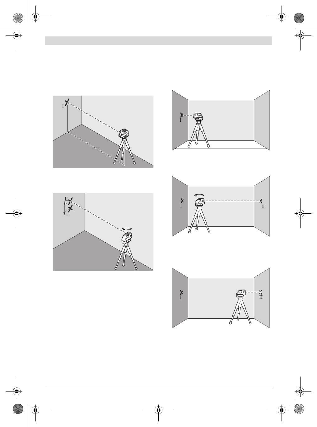
Checking the Horizontal Levelling Accuracy of the Lateral
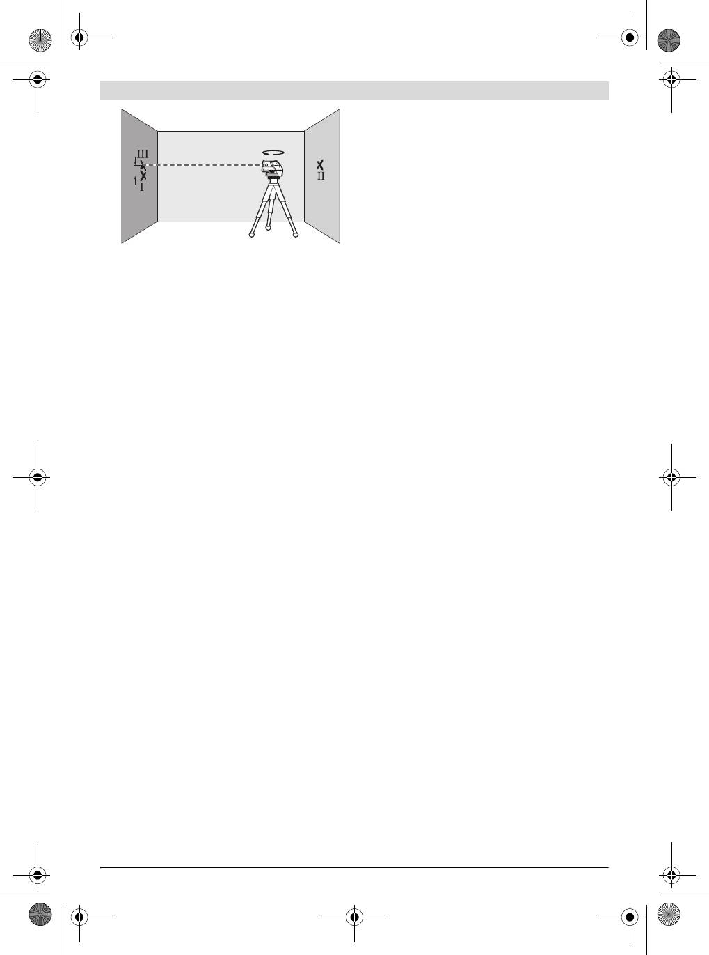
Checking the Horizontal Levelling Accuracy of the Longi-
Axis
tudinal Axis
A free measuring distance of 20 m on a firm surface in front of
A free measuring distance of 20 m on a firm surface between
a wall is required for the check.
two walls A and B is required for the check.
– Mount the measuring tool onto the holder or a tripod, or
– Mount the measuring tool onto the holder or a tripod, or
place it on a firm and level surface at a distance of 20 m to
place it on a firm and level surface close to wall A. Switch
the wall. Switch the measuring tool on and select 5-point
the measuring tool on and select 5-point operation.
operation.
A
B
20 m
20 m
– Direct the horizontal laser beam, which runs parallel to the
longitudinal axis of the measuring tool, at the close wall A.
Allow the measuring tool to level in. Mark the centre of the
– Direct one of the two lateral laser beams, that run along-
laser beam on the wall (point I).
side the lateral axis of the measuring tool, at the wall. Allow
the measuring tool to level in. Mark the centre of the laser
beam on the wall (point I).
A
180°
B
d
180°
– Turn the measuring tool around by 180°, allow it to level in
and mark the centre point of the laser beam on the oppo-
site wall B (point II).
– Without turning the measuring tool, position it close to wall
B. Switch the measuring tool on and allow it to level in.
– Rotate the measuring tool by approx. 180° without chang-
ing its height. Allow it to level in and mark the centre point
A
B
of the other lateral laser beam on the wall (point II). Take
care that point II is as vertical as possible above or below
point I.
– The difference d of both marked points I and II on the wall
results in the actual height deviation of the measuring tool
alongside the lateral axis.
On the measuring distance of 2 x 20 m = 40 m, the maximum
allowable deviation is:
40 m x ± 0.3 mm/m = ± 12 mm.
– Align the height of the measuring tool (using the tripod or
Thus, the difference d between points I and II may not exceed
by underlaying, if required) in such a manner that the cen-
12 mm (max.).
tre point of the laser beam is projected exactly against the
previously marked point II on wall B.
1 618 C00 50R | (9.7.12) Bosch Power Tools
OBJ_BUCH-1546-002.book Page 15 Monday, July 9, 2012 10:30 AM
English | 15
Working with the Laser Target Plate
The laser target plate 13 increases the visibility of the laser
A
B
180°
beam under unfavourable conditions and at large distances.
The reflective part of the laser target plate 13 improves the
d
visibility of the laser line. Thanks to the transparent part, the
laser line is also visible from the back side of the laser target
plate.
Laser Viewing Glasses (Accessory)
The laser viewing glasses filter out the ambient light. This
makes the red light of the laser appear brighter for the eyes.
– Rotate the measuring tool by 180° without changing the
f Do not use the laser viewing glasses as safety goggles.
height. Allow it to level in and mark the centre point of the
The laser viewing glasses are used for improved visualisa-
laser beam on wall A (point III). Take care that point III is
tion of the laser beam, but they do not protect against laser
as vertical as possible above or below point I.
radiation.
– The difference d of both marked points I and III on wall A
f Do not use the laser viewing glasses as sun glasses or in
results in the actual height deviation of the measuring tool
traffic. The laser viewing glasses do not afford complete
alongside the Longitudinal axis.
UV protection and reduce colour perception.
On the measuring distance of 2 x 20 m = 40 m, the maximum
Work Examples (see figures C – F)
allowable deviation is: 40 m x ± 0.3 mm/m = ± 12 mm.
Applicational examples for the measuring tool can be found
Thus, the difference d between points I and III may not ex-
on the graphics pages.
ceed 12 mm (max.).
Always position the measuring tool close to the surface or
Working Advice
edge subject to checking, and allow it to level in prior to each
measurement.
f For marking, always use only the centre of the laser
point or the laser line. The size of the laser point as well as
Always measure the distances between laser beam or laser
the width of the laser line change with distance.
line and a surface or edge at two points as far as possible away
from each other (e.g. with the measurment plate 14).
Working with the Tripod (Accessory)
A tripod offers a stable, height-adjustable measuring support.
Maintenance and Service
Position the measuring tool with the 1/4" tripod mount 7 onto
the thread of the tripod 16 or a commercially available cam-
Maintenance and Cleaning
era tripod. For fastening to a commercially available construc-
Store and transport the measuring tool only in the supplied
tion tripod, use the 5/8" tripod mount 6. Tighten the measur-
case.
ing tool with the tripod mounting stud.
Keep the measuring tool clean at all times.
Adjust the tripod roughly before switching on the measuring
Do not immerse the measuring tool in water or other fluids.
tool.
Wipe off debris using a moist and soft cloth. Do not use any
Fastening with the Universal Holder (Accessory)
cleaning agents or solvents.
With the universal holder 15, you can fasten the measuring
Regularly clean the surfaces at the exit opening of the laser in
tool, e.g., to vertical surfaces, pipes or magnetizable materials.
particular, and pay attention to any fluff of fibres.
The universal holder is also suitable for use as a ground tripod
If the measuring tool should fail despite the care taken in man-
and makes the height adjustment of the measuring tool easier.
ufacturing and testing procedures, repair should be carried
Adjust the universal holder roughly before 15 switching on
out by an authorised after-sales service centre for Bosch
the measuring tool.
power tools. Do not open the measuring tool yourself.
Working with the Measuring Plate (Accessory)
In all correspondence and spare parts orders, please always
(see figures A–B)
include the 10-digit article number given on the type plate of
With the measuring plate 14, it is possible to project the laser
the measuring tool.
mark onto the floor or the laser height onto a wall.
For repairs, only send in the measuring tool in the case.
With the zero field and the scale, the offset or drop to the
After-sales Service and Customer Assistance
required height can be measured and projected at another
location. This eliminates the necessity of precisely adjusting
Our after-sales service responds to your questions concern-
the measuring tool to the height to be projected.
ing maintenance and repair of your product as well as spare
parts. Exploded views and information on spare parts can
The measuring plate 14 has a reflective coating that enhances
also be found under:
the visibility of the laser beam at greater distances or in
www.bosch-pt.com
intense sunlight. The brightness intensification can be seen
Our customer service representatives can answer your ques-
only when viewing, parallel to the laser beam, onto the meas-
tions concerning possible applications and adjustment of
uring plate.
products and accessories.
Bosch Power Tools 1 618 C00 50R | (9.7.12)
OBJ_BUCH-1546-002.book Page 16 Monday, July 9, 2012 10:30 AM
16 | English
Great Britain
Bosch Headquarters
Robert Bosch Ltd. (B.S.C.)
Midrand, Gauteng
P.O. Box 98
Tel.: +27 (011) 6 51 96 00
Broadwater Park
Fax: +27 (011) 6 51 98 80
North Orbital Road
E-Mail: rbsa-hq.pts@za.bosch.com
Denham
People’s Republic of China
Uxbridge
China Mainland
UB 9 5HJ
Bosch Power Tools (China) Co., Ltd.
Tel. Service: +44 (0844) 736 0109
567, Bin Kang Road
Fax: +44 (0844) 736 0146
Bin Jiang District 310052
E-Mail: boschservicecentre@bosch.com
Hangzhou, P.R.China
Ireland
Service Hotline: 400 826 8484
Origo Ltd.
Fax: +86 571 8777 4502
Unit 23 Magna Drive
E-Mail: contact.ptcn@cn.bosch.com
Magna Business Park
www.bosch-pt.com.cn
City West
HK and Macau Special Administrative Regions
Dublin 24
Robert Bosch Hong Kong Co. Ltd.
Tel. Service: +353 (01) 4 66 67 00
21st Floor, 625 King’s Road
Fax: +353 (01) 4 66 68 88
North Point, Hong Kong
Australia, New Zealand and Pacific Islands
Customer Service Hotline: +852 2101 0235
Robert Bosch Australia Pty. Ltd.
Fax: +852 2590 9762
Power Tools
E-Mail: info@hk.bosch.com
Locked Bag 66
www.bosch-pt.com.hk
Clayton South VIC 3169
Indonesia
Customer Contact Center
PT. Multi Mayaka
Inside Australia:
Kawasan Industri Pulogadung
Phone: +61 (01300) 307 044
Jalan Rawa Gelam III No. 2
Fax: +61 (01300) 307 045
Jakarta 13930
Inside New Zealand:
Indonesia
Phone: +64 (0800) 543 353
Tel.: +62 (21) 46 83 25 22
Fax: +64 (0800) 428 570
Fax: +62 (21) 46 82 86 45/68 23
Outside AU and NZ:
E-Mail: sales@multimayaka.co.id
Phone: +61 (03) 9541 5555
www.bosch-pt.co.id
www.bosch.com.au
Philippines
Republic of South Africa
Robert Bosch, Inc.
Customer service
28th Floor Fort Legend Towers,
Hotline: +27 (011) 6 51 96 00
3rd Avenue corner 31st Street,
Gauteng – BSC Service Centre
Fort Bonifacio Global City,
35 Roper Street, New Centre
1634 Taguig City, Philippines
Johannesburg
Tel.: +63 (2) 870 3871
Tel.: +27 (011) 4 93 93 75
Fax: +63 (2) 870 3870
Fax: +27 (011) 4 93 01 26
matheus.contiero@ph.bosch.com
E-Mail: bsctools@icon.co.za
www.bosch-pt.com.ph
KZN – BSC Service Centre
Bosch Service Center:
Unit E, Almar Centre
9725-27 Kamagong Street
143 Crompton Street
San Antonio Village
Pinetown
Makati City, Philippines
Tel.: +27 (031) 7 01 21 20
Tel.: +63 (2) 899 9091
Fax: +27 (031) 7 01 24 46
Fax: +63 (2) 897 6432
E-Mail: bsc.dur@za.bosch.com
rosalie.dagdagan@ph.bosch.com
Western Cape – BSC Service Centre
Democracy Way, Prosperity Park
Milnerton
Tel.: +27 (021) 5 51 25 77
Fax: +27 (021) 5 51 32 23
E-Mail: bsc@zsd.co.za
1 618 C00 50R | (9.7.12) Bosch Power Tools
Оглавление
- Deutsch
- English
- Français
- Español
- Português
- Italiano
- Nederlands
- Dansk
- Svenska
- Norsk
- Suomi
- ÅëëçíéêÜ
- Türkçe
- Polski
- Česky
- Slovensky
- Magyar
- Ðóññêèé
- Óêðà¿íñüêà
- Română
- Áúëãàðñêè
- Srpski
- Slovensko
- Hrvatski
- Eesti
- Latviešu
- Lietuviškai
- 日本語
- 中文
- กฎระเบียบเพื่อความปลอดภัย
- รายละเอียดผลิตภัณฑและขอมูลจําเพาะ
- การประกอบ
- การบํารุงรักษาและการบริการ
- Bahasa Indonesia
- Tiøng Vi·t
