Bosch GPL 5 Professional: English
English: Bosch GPL 5 Professional
OBJ_BUCH-815-002.book Page 8 Tuesday, March 13, 2012 2:43 PM
8 | English
Wartung und Service
Schweiz
Tel.: +41 (044) 8 47 15 11
Wartung und Reinigung
Fax: +41 (044) 8 47 15 51
Lagern und transportieren Sie das Messwerkzeug nur in der
mitgelieferten Schutztasche.
Luxemburg
Tel.: +32 2 588 0589
Halten Sie das Messwerkzeug stets sauber.
Fax: +32 2 588 0595
Tauchen Sie das Messwerkzeug nicht ins Wasser oder andere
E-Mail: outillage.gereedschap@be.bosch.com
Flüssigkeiten.
Wischen Sie Verschmutzungen mit einem feuchten, weichen
Entsorgung
Tuch ab. Verwenden Sie keine Reinigungs- oder Lösemittel.
Messwerkzeuge, Zubehör und Verpackungen sollen einer
Reinigen Sie insbesondere die Flächen an der Austrittsöff-
umweltgerechten Wiederverwertung zugeführt werden.
nung des Lasers regelmäßig und achten Sie dabei auf Fusseln.
Werfen Sie Messwerkzeuge und Akkus/Batterien nicht in den
Sollte das Messwerkzeug trotz sorgfältiger Herstellungs- und
Hausmüll!
Prüfverfahren einmal ausfallen, ist die Reparatur von einer auto-
risierten Kundendienststelle für Bosch-Elektrowerkzeuge aus-
Nur für EU-Länder:
führen zu lassen. Öffnen Sie das Messwerkzeug nicht selbst.
Gemäß der europäischen Richtlinie
Geben Sie bei allen Rückfragen und Ersatzteilbestellungen
2002/96/EG müssen nicht mehr ge-
bitte unbedingt die 10-stellige Sachnummer laut Typenschild
brauchsfähige Messwerkzeuge und gemäß
des Messwerkzeugs an.
der europäischen Richtlinie 2006/66/EG
Senden Sie im Reparaturfall das Messwerkzeug in der Schutz-
müssen defekte oder verbrauchte Akkus/
tasche 16 ein.
Batterien getrennt gesammelt und einer
umweltgerechten Wiederverwendung zu-
Kundendienst und Kundenberatung
geführt werden.
Der Kundendienst beantwortet Ihre Fragen zu Reparatur und
Nicht mehr gebrauchsfähige Akkus/Batterien können direkt
Wartung Ihres Produkts sowie zu Ersatzteilen. Explosions-
abgegeben werden bei:
zeichnungen und Informationen zu Ersatzteilen finden Sie
Deutschland
auch unter:
Recyclingzentrum Elektrowerkzeuge
www.bosch-pt.com
Osteroder Landstraße 3
Das Bosch-Kundenberater-Team hilft Ihnen gerne bei Fragen
37589 Kalefeld
zu Kauf, Anwendung und Einstellung von Produkten und Zu-
Schweiz
behören.
Batrec AG
3752 Wimmis BE
www.powertool-portal.de, das Internetportal für Hand-
werker und Heimwerker.
Änderungen vorbehalten.
www.ewbc.de, der Informations-Pool für Handwerk und
Ausbildung.
Deutschland
Robert Bosch GmbH
English
Servicezentrum Elektrowerkzeuge
Zur Luhne 2
Safety Notes
37589 Kalefeld – Willershausen
Tel. Kundendienst: +49 (1805) 70 74 10*
Point Laser
Fax: +49 (1805) 70 74 11*
(*Festnetzpreis 14 ct/min, höchstens 42 ct/min aus Mobil-
Working safely with the measuring tool is
funknetzen)
possible only when the operating and safety
E-Mail: Servicezentrum.Elektrowerkzeuge@de.bosch.com
information are read completely and the in-
Tel. Kundenberatung: +49 (1803) 33 57 99
structions contained therein are strictly fol-
(Festnetzpreis 9 ct/min, höchstens 42 ct/min aus Mobil-
lowed. Never make warning labels on the
funknetzen)
measuring tool unrecognisable. SAVE
Fax: +49 (711) 7 58 19 30
THESE INSTRUCTIONS.
E-Mail: kundenberatung.ew@de.bosch.com
f Caution – The use of other operating or adjusting
equipment or the application of other processing meth-
Österreich
ods than those mentioned here, can lead to dangerous
Tel.: +43 (01) 7 97 22 20 10
radiation exposure.
Fax: +43 (01) 7 97 22 20 11
E-Mail: service.elektrowerkzeuge@at.bosch.com
1 609 929 S07 | (13.3.12) Bosch Power Tools
OBJ_BUCH-815-002.book Page 9 Tuesday, March 13, 2012 2:43 PM
English | 9
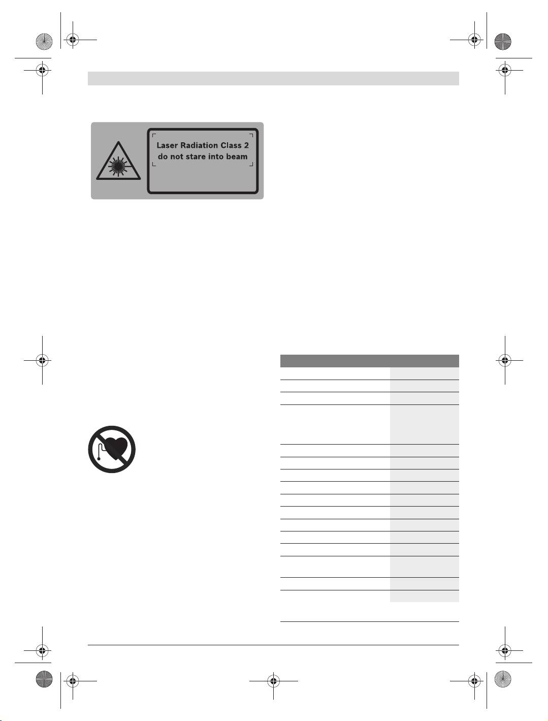
f The measuring tool is provided with a warning label in
Product Features
English (marked with number 5 in the representation
The numbering of the product features shown refers to the
of the measuring tool on the graphics page).
illustration of the measuring tool on the graphic page.
1 Exit opening for laser beam
2 Latch of battery lid
3 Battery lid
4 On/Off switch
IEC 60825-1:2007-03
5 Laser warning label
<
1 mW, 635 nm
6 Tripod mount 1/4"
7 Serial number
8 Holder
f Do not direct the laser beam at persons or animals and
do not stare into the laser beam yourself. This measur-
9 Locking screw for holder
ing tool produces laser class 2 laser radiation according to
10 Screw holes of holder
IEC 60825-1. This can lead to persons being blinded.
11 Opening for strap attachment
f Do not use the laser viewing glasses as safety goggles.
12 Magnets
The laser viewing glasses are used for improved visualisa-
13 1/4" tripod mount on holder
tion of the laser beam, but they do not protect against laser
14 5/8" tripod mount on holder
radiation.
15 Measuring plate with stand*
f Do not use the laser viewing glasses as sun glasses or in
16 Protective pouch
traffic. The laser viewing glasses do not afford complete
17 Laser viewing glasses*
UV protection and reduce colour perception.
18 Tripod*
f Have the measuring tool repaired only through quali-
* The accessories illustrated or described are not included as
fied specialists using original spare parts. This ensures
standard delivery.
that the safety of the measuring tool is maintained.
f Do not allow children to use the laser measuring tool
Technical Data
without supervision. They could unintentionally blind
other persons or themselves.
Point Laser GPL 5
f Do not operate the measuring tool in explosive environ-
Article number
3 601 K66 2..
ments, such as in the presence of flammable liquids,
Working range
30 m
gases or dusts. Sparks can be created in the measuring
tool which may ignite the dust or fumes.
Levelling Accuracy
±0.3 mm/m
Self-levelling range (typical) along-
Holder
side the
Keep the holder 8 away from cardiac
– longitudinal axis
± 5°
pacemakers. The magnets 12 generate a
– lateral axis
± 3°
field that can impair the function of cardiac
Levelling duration, typically
<4s
pacemakers.
Operating temperature
–10 °C...+40 °C
Storage temperature
–20 °C...+70 °C
f Keep the holder 8 away from magnetic data medium
and magnetically-sensitive equipment. The effect of the
Relative air humidity, max.
90 %
magnets 12 can lead to irreversible data loss.
Laser class
2
Laser type
635 nm, <1 mW
Product Description and
Tripod mount
1/4"
Specifications
Batteries
3x1.5VLR06(AA)
Please unfold the fold-out page with the representation of the
Operating life time, approx.
24 h
measuring tool and leave it unfolded while reading the operat-
Weight according to
ing instructions.
EPTA-Procedure 01/2003
0.25 kg
Intended Use
Dimensions (length x width x height)
104x40x80mm
The measuring tool is intended for determining and checking
Degree of protection
IP 5X
horizontal and vertical lines as well as plumb points.
The measuring tool can be clearly identified with the serial number 7 on
the type plate.
Bosch Power Tools 1 609 929 S07 | (13.3.12)
OBJ_BUCH-815-002.book Page 10 Tuesday, March 13, 2012 2:43 PM
10 | English
Assembly
Setting the Automatic Switch-off
By default, the measuring tool automatically shuts off
Inserting/Replacing the Battery
20 minutes after being switched on.
Alkali-manganese batteries are recommended for the meas-
The automatic switch-off can be set from 20 minutes to
uring tool.
8 hours. For this, switch the measuring tool on, then immedi-
To open the battery compartment 3, turn the latch 2 in clock-
ately off, and then on again within 4 s. To confirm the change,
wise direction to position and pull off the battery lid. In-
all laser beams will flash quickly for 2 s after switching on the
sert the batteries provided. When inserting, pay attention to
second time.
the correct polarity according to the representation on the in-
f Do not leave the switched on measuring tool unattend-
side of the battery compartment.
ed and switch the measuring tool off after use. Other
Position the battery lid to the bottom of the housing and then
persons could be blinded by the laser beam.
push it upward. To lock the battery lid, turn the latch 2 in anti-
When switching on the measuring tool the next time, the auto-
clockwise direction to the position.
matic switch-off is set to 20 minutes again.
When the laser beams flash slowly during operation, the bat-
Working with Automatic Levelling
teries are low. When the flashing begins, the measuring tool
Position the measuring tool on a level and firm support, attach
can be operated for approx. 8 h.
it to the holder 8 or to the tripod 18.
Always replace all batteries at the same time. Only use batter-
After switching on, the automatic levelling function automati-
ies from one brand and with the identical capacity.
cally compensates irregularities within the self-levelling range
f Remove the batteries from the measuring tool when
from ± 5° (longitudinal axis) and ± 3° (lateral axis). The level-
not using it for extended periods. When storing for ex-
ling is finished as soon as the laser points do not move any
tended periods, the batteries can corrode and discharge
more.
themselves.
If the automatic levelling function is not possible, e.g. be-
cause the surface on which the measuring tool stands devi-
Operation
ates by more than 5 ° or 3 ° from the horizontal plane, the laser
beams flash rapidly. In this case, bring the measuring tool to
Initial Operation
the level position and wait for the self-levelling to take place.
f Protect the measuring tool against moisture and direct
As soon as the measuring tool is within the self-levelling range
sun light.
of ± 5° or ±3° respectively, all laser beams light up continu-
f Do not subject the measuring tool to extreme tempera-
ously again.
tures or variations in temperature. As an example, do
In case of ground vibrations or position changes during oper-
not leave it in vehicles for long time. In case of large varia-
ation, the measuring tool is automatically levelled in again. To
tions in temperature, allow the measuring tool to adjust to
avoid errors by moving the measuring tool, check the position
the ambient temperature before putting it into operation.
of the laser beams with regard to the reference points upon
In case of extreme temperatures or variations in tempera-
re-levelling.
ture, the accuracy of the measuring tool can be impaired.
Levelling Accuracy
f Avoid heavy impact or falling of the measuring tool.
After heavy exterior impact on the measuring tool, an accu-
Influences on Accuracy
racy check should always be carried out before continuing
The ambient temperature has the greatest influence. Espe-
to work (see “Levelling Accuracy”).
cially temperature differences occurring from the ground up-
f Switch the measuring tool off during transport. When
ward can divert the laser beam.
switching off, the levelling unit, which can be damaged in
As thermal fluctuation is largest close to the ground, the
case of intense movement, is locked.
measuring tool, if possible, should be mounted on a commer-
Switching On and Off
cially available tripod and placed in the centre of the working
area.
To switch on the measuring tool, push the On/Off switch 4
upward so that “I” is indicated on the switch. Immediately
Apart from exterior influences, device-specific influences
after switching on, the measuring tool sends a laser beam out
(such as heavy impact or falling down) can lead to deviations.
of each exit opening 1.
Therefore, check the accuracy of the measuring tool each
time before starting your work.
f Do not point the laser beam at persons or animals and
do not look into the laser beam yourself, not even from
Should the measuring tool exceed the maximum deviation
a large distance.
during one of the tests, please have it repaired by a Bosch
after-sales service.
To switch off the measuring tool, push the On/Off switch 4
downward so that “0” is indicated on the switch. When
When the levelling accuracy of the horizontal laser beams for
switching off, the levelling unit is locked.
the lateral and longitudinal axis is within the maximum allow-
able deviation, then the levelling accuracy for the plumb
beams (vertical axis) is thus also checked.
1 609 929 S07 | (13.3.12) Bosch Power Tools
OBJ_BUCH-815-002.book Page 11 Tuesday, March 13, 2012 2:43 PM
English | 11
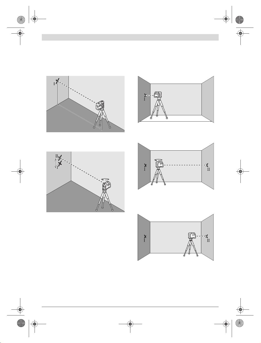
Checking the Horizontal Levelling Accuracy of the
Checking the Horizontal Levelling Accuracy of the
Lateral Axis
Longitudinal Axis
A free measuring distance of 20 m on a firm surface in front of
A free measuring distance of 20 m on a firm surface between
a wall is required for the check.
two walls A and B is required for the check.
– Mount the measuring tool onto the holder or a tripod, or
– Mount the measuring tool onto the holder or a tripod, or
place it on a firm and level surface at a distance of 20 m to
place it on a firm and level surface close to wall A. Switch
the wall. Switch the measuring tool on.
the measuring tool on.
A
B
20 m
20 m
– Direct the horizontal laser beam, which runs parallel to the
longitudinal axis of the measuring tool, at the close wall A.
– Direct one of the two lateral laser beams, that run along-
Allow the measuring tool to level in. Mark the centre of the
side the lateral axis of the measuring tool, at the wall. Allow
laser beam on the wall (point I).
the measuring tool to level in. Mark the centre of the laser
beam on the wall (point I).
A
B
180˚
d
180˚
– Turn the measuring tool around by 180°, allow it to level in
and mark the centre point of the laser beam on the oppo-
site wall B (point II).
– Without turning the measuring tool, position it close to wall
B. Switch the measuring tool on and allow it to level in.
– Rotate the measuring tool by approx. 180° without chang-
ing its height. Allow it to level in and mark the centre point
of the other lateral laser beam on the wall (point II). Take
A
B
care that point II is as vertical as possible above or below
point I.
– The difference d of both marked points I and II on the wall
results in the actual height deviation of the measuring tool
alongside the lateral axis.
On the measuring distance of 2 x 20 m = 40 m, the maximum
allowable deviation is:
40 m x ± 0,3 mm/m = ± 12 mm.
Thus, the difference d between points I and II may not exceed
– Align the height of the measuring tool (using the tripod or
12 mm (max.).
by underlaying, if required) in such a manner that the cen-
tre point of the laser beam is projected exactly against the
previously marked point II on wall B.
Bosch Power Tools 1 609 929 S07 | (13.3.12)

OBJ_BUCH-815-002.book Page 12 Tuesday, March 13, 2012 2:43 PM
12 | English
Working with the Measuring Plate (Accessory)
With the measuring plate 15, it is possible to project the laser
A
180˚
B
mark onto the floor or the laser height onto a wall.
With the zero field and the scale, the offset or drop to the re-
d
quired height can be measured and projected at another loca-
tion. This eliminates the necessity of precisely adjusting the
measuring tool to the height to be projected.
The measuring plate 15 has a reflective coating that enhances
the visibility of the laser beam at greater distances or in in-
tense sunlight. The brightness intensification can be seen on-
ly when viewing, parallel to the laser beam, onto the measur-
– Rotate the measuring tool by 180° without changing the
ing plate.
height. Allow it to level in and mark the centre point of the
laser beam on wall A (point III). Take care that point III is
Laser Viewing Glasses (Accessory)
as vertical as possible above or below point I.
The laser viewing glasses filter out the ambient light. This
– The difference d of both marked points I and III on wall A
makes the red light of the laser appear brighter for the eyes.
results in the actual height deviation of the measuring tool
f Do not use the laser viewing glasses as safety goggles.
alongside the Longitudinal axis.
The laser viewing glasses are used for improved visualisa-
On the measuring distance of 2 x 20 m = 40 m, the maximum
tion of the laser beam, but they do not protect against laser
allowable deviation is: 40 m x ± 0,3 mm/m = ± 12 mm.
radiation.
Thus, the difference d between points I and III may not ex-
f Do not use the laser viewing glasses as sun glasses or in
ceed 12 mm (max.).
traffic. The laser viewing glasses do not afford complete
UV protection and reduce colour perception.
Working Advice
f Always use the centre of the laser point for marking.
The size of the laser point changes with the distance.
Maintenance and Service
Attaching with the Holder
Maintenance and Cleaning
To fasten the measuring tool on the holder 8, screw the lock-
Store and transport the measuring tool only in the supplied
ing screw 9 of the holder into the 1/4" tripod mount 6 on the
protective pouch.
measuring tool and tighten. To rotate the measuring tool on
Keep the measuring tool clean at all times.
the holder, slightly loosen the screw 9.
Do not immerse the measuring tool in water or other fluids.
– Rotate the measuring tool on the holder 8 sideward or to-
Wipe off debris using a moist and soft cloth. Do not use any
ward the rear to make the bottom plumb beam visible.
cleaning agents or solvents.
– Rotate the measuring tool on the holder 8 to project
heights with the horizontal laser beam.
Regularly clean the surfaces at the exit opening of the laser in
particular, and pay attention to any fluff of fibres.
With the holder 8, the measuring tool can be attached as
follows:
If the measuring tool should fail despite the care taken in man-
ufacturing and testing procedures, repair should be carried
– Mount the holder 8 to the tripod 18 or a commercially
out by an authorised after-sales service centre for Bosch pow-
available camera tripod via the 1/4" tripod mount 13. For
er tools. Do not open the measuring tool yourself.
fastening to a commercially available construction tripod,
use the 5/8" tripod mount 14.
In all correspondence and spare parts orders, please always
– The holder 8 can be fastened to steel parts via the magnets
include the 10-digit article number given on the type plate of
12.
the measuring tool.
– The holder 8 can be fastened to drywalls or wood walls
In case of repairs, send in the measuring tool packed in its
with screws. For this, insert screws with a minimum length
protective pouch 16.
of 60 mm into the screw holes 10 of the holder.
– The holder 8 can also be fastened to pipes or similar beams
After-sales Service and Customer Assistance
using a commercially available strap by threading it
Our after-sales service responds to your questions concern-
through the opening 11 for strap attachment.
ing maintenance and repair of your product as well as spare
Working with the Tripod (Accessory)
parts. Exploded views and information on spare parts can
also be found under:
A tripod 18 offers a stable, height-adjustable measuring sup-
www.bosch-pt.com
port. Place the measuring tool via the tripod mount 6 onto the
Our customer service representatives can answer your ques-
1/4" male thread of the tripod and screw the locking screw of
tions concerning possible applications and adjustment of
the tripod tight.
products and accessories.
1 609 929 S07 | (13.3.12) Bosch Power Tools
OBJ_BUCH-815-002.book Page 13 Tuesday, March 13, 2012 2:43 PM
English | 13
Great Britain
Bosch Headquarters
Robert Bosch Ltd. (B.S.C.)
Midrand, Gauteng
P.O. Box 98
Tel.: +27 (011) 6 51 96 00
Broadwater Park
Fax: +27 (011) 6 51 98 80
North Orbital Road
E-Mail: rbsa-hq.pts@za.bosch.com
Denham
Uxbridge
People’s Republic of China
UB 9 5HJ
China Mainland
Tel. Service: +44 (0844) 736 0109
Bosch Power Tools (China) Co., Ltd.
Fax: +44 (0844) 736 0146
567, Bin Kang Road
E-Mail: boschservicecentre@bosch.com
Bin Jiang District 310052
Hangzhou, P.R.China
Ireland
Service Hotline: 400 826 8484
Origo Ltd.
Fax: +86 571 8777 4502
Unit 23 Magna Drive
E-Mail: contact.ptcn@cn.bosch.com
Magna Business Park
www.bosch-pt.com.cn
City West
Dublin 24
HK and Macau Special Administrative Regions
Tel. Service: +353 (01) 4 66 67 00
Robert Bosch Hong Kong Co. Ltd.
Fax: +353 (01) 4 66 68 88
21st Floor, 625 King’s Road
North Point, Hong Kong
Australia, New Zealand and Pacific Islands
Customer Service Hotline: +852 2101 0235
Robert Bosch Australia Pty. Ltd.
Fax: +852 2590 9762
Power Tools
E-Mail: info@hk.bosch.com
Locked Bag 66
www.bosch-pt.com.hk
Clayton South VIC 3169
Customer Contact Center
Indonesia
Inside Australia:
PT. Multi Mayaka
Phone: +61 (01300) 307 044
Kawasan Industri Pulogadung
Fax: +61 (01300) 307 045
Jalan Rawa Gelam III No. 2
Inside New Zealand:
Jakarta 13930
Phone: +64 (0800) 543 353
Indonesia
Fax: +64 (0800) 428 570
Tel.: +62 (21) 46 83 25 22
Outside AU and NZ:
Fax: +62 (21) 46 82 86 45/68 23
Phone: +61 (03) 9541 5555
E-Mail: sales@multimayaka.co.id
www.bosch.com.au
www.bosch-pt.co.id
Republic of South Africa
Philippines
Customer service
Robert Bosch, Inc.
Hotline: +27 (011) 6 51 96 00
28th Floor Fort Legend Towers,
Gauteng – BSC Service Centre
3rd Avenue corner 31st Street,
35 Roper Street, New Centre
Fort Bonifacio Global City,
Johannesburg
1634 Taguig City, Philippines
Tel.: +27 (011) 4 93 93 75
Tel.: +63 (2) 870 3871
Fax: +27 (011) 4 93 01 26
Fax: +63 (2) 870 3870
E-Mail: bsctools@icon.co.za
matheus.contiero@ph.bosch.com
KZN – BSC Service Centre
www.bosch-pt.com.ph
Unit E, Almar Centre
Bosch Service Center:
143 Crompton Street
9725-27 Kamagong Street
Pinetown
San Antonio Village
Tel.: +27 (031) 7 01 21 20
Makati City, Philippines
Fax: +27 (031) 7 01 24 46
Tel.: +63 (2) 899 9091
E-Mail: bsc.dur@za.bosch.com
Fax: +63 (2) 897 6432
Western Cape – BSC Service Centre
rosalie.dagdagan@ph.bosch.com
Democracy Way, Prosperity Park
Milnerton
Tel.: +27 (021) 5 51 25 77
Fax: +27 (021) 5 51 32 23
E-Mail: bsc@zsd.co.za
Bosch Power Tools 1 609 929 S07 | (13.3.12)
