Bosch FCS-320-TP Series Conventional Aspirating Smoke Detectors: Installation
Installation: Bosch FCS-320-TP Series Conventional Aspirating Smoke Detectors
24
en
FCS-320-TP1 | FCS-320-TP2 | FCS-320-TT1 | FCS-320-TT2
F.01U.130.927 | 2.0 | 2010.12
Bosch Sicherheitssysteme GmbH
Installation
FCS-320-TP1 and FCS-320-TP2 System Overview
See
Figure 1, Page 4
FCS-320-TT1 and FCS-320-TT2 System Overview
See
Figure 2, Page 4
Jumper Assignment
See
Figure 4, Page 5
CAUTION!
Installation must only be performed by authorized and specialized personnel!Switch off the
unit before carrying out the following work.Do not connect or disconnect the detector module
while switched on!
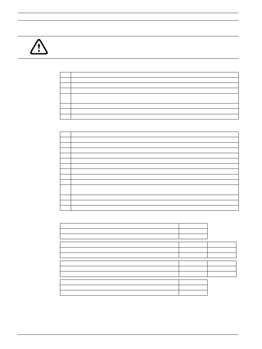
1
Operating LED
2
Alarm LED for detector module 1
3
Alarm LED for detector module 2 (for FCS-320-TP2 only)
4
Collective fault LED
5
Pre-punched cable entries for connection to the fire panel and power supply
(input/output)
6
Pipe system 1 connection
7
Pipe system 2 connection (required for FCS-320-TP2 only)
8
Connection for air return pipe
1
Operating LED
2
Collective fault LED
3
Info alarm LED for detector module 1
4
Pre-alarm LED for detector module 1
5
Main alarm LED for detector module 1
6
Smoke level display in ten levels, detector module 1
7
Info alarm LED for detector module 2 (for FCS-320-TT2 only)
8
Pre-alarm LED for detector module 2 (for FCS-320-TT2 only)
9
Main alarm LED for detector module 2 (for FCS-320-TT2 only)
10
Smoke level display in ten levels, detector module 2 (for FCS-320-TT2 only)
11
Pre-punched cable entries for connection to the fire panel and power supply (input/
output)
12
Pipe system 1 connection
13
Pipe system 2 connection (required for FCS-320-TT2 only)
14
Connection for air return pipe
Jumper JU1: fan voltage
Pin 1+2
6.9 V
Bypassed
9 V
Open
Jumper JU2: collective fault contact for detector module 1 Pin 1+2
Pin 2+3
NC contact
Bypassed
Open
NO contact
Open
Bypassed
Jumper JU3: collective fault contact for detector module 2 Pin 1+2
Pin 2+3
NC contact
Bypassed
Open
NO contact
Open
Bypassed
Jumper JU4: number of detector modules
Pin 1+2
1 detector module
Bypassed
2 detector modules
Open

FCS-320-TP1 | FCS-320-TP2 | FCS-320-TT1 | FCS-320-TT2
en
25
Bosch Sicherheitssysteme GmbH
F.01U.130.927 | 2.0 | 2010.12
Installing the Detector Module
See
Figure 3, Page 4
:
1.
Open the unit by carefully unlocking the housing cover's quick-release locks with a
screwdriver and then removing the housing cover.
2.
Carefully disconnect the display board connection cable from the motherboard ("DISPL."
connection) and remove the housing cover.
1.
Spread the brackets provided for fixing the detector module slightly apart.
2.
Carefully insert the detector module until you hear it click into place. Make sure that the
used detector module is fixed tightly and securely by the bracket by additionally pushing
together the brackets by hand.
3.
Connect detector module 1 to the "HEAD1" connection on the motherboard using the
flatband cable.
FCS-320-TP2 and FCS-320-TT2 variants:
Connect detector module 2 to the "HEAD 2" connection on the motherboard using the
flatband cable.
4.
Reconnect the display board connection cable to the "DISPL." connection on the
motherboard.
Setting the Fan Voltage
See
Figure 4, Page 5
: with jumper JU1, the fan voltage is set on the motherboard. The default
setting is marked in bold.
Number of Detector Modules
See
Figure 4, Page 5
: The number of populated detector modules is factory set in line with the
model variant (jumper JU4 on the unit's motherboard).
Installing the Unit
NOTICE!
Only DM-TP-50(80), DM-TP-10(25) and DM-TP-01(05) detector modules certified to VdS may
be used in the FCS-320-TP1/TP2. Only DM-TT-50(80), DM-TT-10(25) and DM-TT-01(05)
detector modules certified to VdS may be used in the FCS-320-TT1/TT2.The detector module
settings are configured via the DIP switch on the detector module.The sensitivity value is
based on measurements with standard test fires (old value in brackets).
NOTICE!
FCS-320-TP2
and
FCS-320-TT2
variants
:
These units are factory prepared for the installation of two detector modules:
-
The fan covers for both aspiration pipes are removed.
-
The two pipe system connections are cut out.
-
The pin pair on jumper JU4 is open (see
Figure 4, Page 5
).
Fan voltage
Jumper JU1, pin no. 1+2
6.9 V X
9 V
O
X = pin pair bypassed / O = pin pair open
Variant
Number of detector modules Jumper JU4, pin no. 1+2
FCS-320-TP1 / FCS-320-TT1
1 detector module
X
FCS-320-TP2 / FCS-320-TT2
2 detector modules
O
X = pin pair bypassed / O = pin pair open
NOTICE!
-
When selecting the installation location, ensure that the unit displays are easily visible.
-
Remember when planning that the unit fans generate a noise level of approx. 45 dB(A).
-
The air outlet on the unit must not be obstructed. The distance between the air outlet
and adjacent components, e.g. a wall, must be at least 10 cm (4 inches).
-
The aspirating smoke detector can be installed with the suction device pointing up or
down (to do this, rotate the housing cover through 180°). If the aspiration pipe points
down, make sure no impurities enter the air return pipe, which will be pointing up.
-
The aspirating smoke detector is either screwed directly to the installation wall by the
rear panel or installed using unit mounting type MT-1, e.g. on frames (see
Figure 5,
Page 5
: 1 = horizontal installation, 2 = vertical installation).

26
en
FCS-320-TP1 | FCS-320-TP2 | FCS-320-TT1 | FCS-320-TT2
F.01U.130.927 | 2.0 | 2010.12
Bosch Sicherheitssysteme GmbH
1.
First, clearly mark the fixing points on the installation position provided on the
equipment. Use the supplied drilling jig as an aid. To guarantee a firm, low-vibration hold,
the unit must be secured with four screws (max. 6 mm
∅
(0.4 inches) for wall mounting,
max. 4 mm
∅
(0.2 inches) for MT-1 unit mounting).
2.
Using four screws appropriate for the installation method, attach the unit securely to the
surface or to the unit mounting. Ensure that the unit is not fixed under mechanical stress
and that the screws are not tightened too tightly, otherwise damage or undesirable
resonance noises could occur.
To balance out unevenness and/or prevent vibrations, vibration absorbers (subject to
separate order) must be used.
3.
Using a screwdriver, carefully punch out the required cable entries on the housing (max.
5 x M20 and 2 x M25).
4.
Fit the cable entry/entries as required with M20 or M25 connections (2 x M25 and 1 x
M20 included in the delivery) by pushing them into the cable entry/entries.
5.
Route the connection cable(s) (max. 2.5 mm
2
) through the prepared M20 or M25
connections and into the unit. Cut them to the required length inside the unit.
6.
Wire the unit according to the connection information described below.
Connecting the FCS-320-TP/-TT series
See
Figure 4, Page 5
:
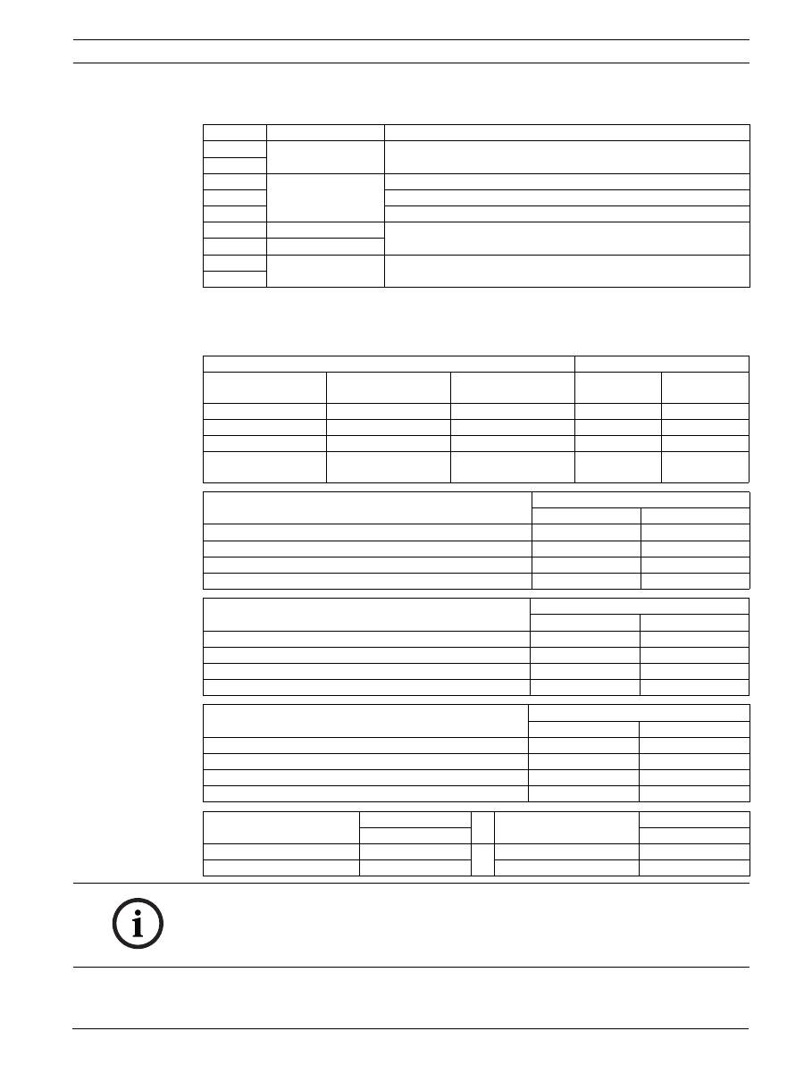
Terminal Terminal block X6 Function
1
Al 1
NO contact for 1st alarm relay
2
C contact for 1st alarm relay
3
NC contact for 1st alarm relay
4
+ Ext. Displ.1
Remote indicator for 1st detector module
5
- Ext. Displ.1
6
+ Reset
+24 V reset input
7
- Reset
0 V reset input
8
+ 24V
+24 V power supply
9
- 24V
0 V power supply
FCS-320-TP1 | FCS-320-TP2 | FCS-320-TT1 | FCS-320-TT2
en
27
Bosch Sicherheitssysteme GmbH
F.01U.130.927 | 2.0 | 2010.12
Connecting the FCS-320-TP/-TT series
See
Figure 4, Page 5
:
Parameter Settings Using the DIP Switch
The aspirating smoke detector parameters are set using the DIP switch on the detector
modules. The default settings are marked in bold in each case. Select all other parameters
(see tables).
Commissioning
See
Figure 5, Page 5
:
Terminal Terminal block X7
1
Fault 2
Fault contact for 2nd detector module
2
3
Al 2
NO contact for 2nd alarm relay
4
C contact for 2nd alarm relay
5
NC contact for 2nd alarm relay
6
+ Ext. Displ.2
Remote indicator for 2nd detector module
7
- Ext. Displ.2
8
Fault 1
Fault contact for 1st detector module
9
Sensitivity
DIP settings
DM-TP-01(05)
DM-TT-01(05)
DM-TP10(25)
DM-TT-10(25)
DM-TP50(80)
DM-TT-50(80)
Switch 1
Switch 2
0,12 %/m(0,4 %/m) 0,8 %/m(2 %/m)
on
on
0,06 %/m(0,2 %/m) 0,4 %/m(1 %/m)
off
on
0,03 %/m(0,1 %/m) 0,2 %/m(0,5 %/m)
1,0 %/m(1,6 %/m)
on
off
0,015 %/m(0,05 %/
m)
0,1 %/m(0,25 %/m)
0,5 %/m(0,8 %/m)
off
off
Alarm delay
DIP settings
Switch 3
Switch 4
0 seconds
off
off
10 seconds
on
off
30 seconds
off
on
60 seconds
on
on
Activation threshold for airflow malfunction
DIP settings
Switch 5
Switch 6
Low (+/- 10% volume flow change)
on
off
Average (+/- 20% volume flow change)
off
on
High (+/- 30% volume flow change)
off
off
Very high (+/- 50% volume flow change)
on
on
Airflow fault delay
DIP settings
Switch 7
Switch 8
30 seconds
off
on
2 minutes
on
off
15 minutes
on
on
60 minutes
off
off
Trouble logging
DIP settings
LOGIC·SENS filter
DIP settings
Switch 9
Switch 10
not saving
off
off
off
saving
on
on
on
NOTICE!
The sensitivity value is based on measurements with standard test fires (old value in
brackets).
The activation threshold for the airflow malfunction is set to 20% volume flow change by
default. Higher values are not permitted within EN 54-20.

28
en
FCS-320-TP1 | FCS-320-TP2 | FCS-320-TT1 | FCS-320-TT2
F.01U.130.927 | 2.0 | 2010.12
Bosch Sicherheitssysteme GmbH
1.
Check the system after installation using the FAS-ASD-DIAG Diagnostic Software.
2.
The unit must be operated for at least 30 min prior to the airflow being initialized to bring
it up to operating temperature.
3.
To initialize the connected pipe system, press the S2 flow-init button (see
Figure 5,
Page 5
) on the detector module concerned until the green operating LED on the unit
starts to flash. Initialization is complete after approx. 10 seconds. Following successful
initialization, the operating LED lights up permanently.
4.
No further modifications may be made to the pipe system during or after initialization.
The unit's fan voltage must also remain unchanged following initialization. Otherwise, the
initialization procedure must be repeated.
Troubleshooting Using Flash Codes
Malfunctions and unit statuses are indicated via the flash codes of the detector module LEDs:
Technical data
Flash code of detector module LEDs
1 flash
Airflow initialization (flow-init) active
2 x flashes
Airflow too small (obstruction)
3 x flashes
Airflow too great (break)
4 x flashes
Unit upload (approx. 2 minutes)
Permanently lit Hardware defect in the detector module
LED flash code on the motherboard (LED1/LED2)
1 flash
Error: internal voltage monitoring 1
2 flashes
Error: internal voltage monitoring 2
3 flashes
Error: fan voltage monitoring
4 flashes
Error: air pressure correction voltage monitoring
5 flashes
Software error
6 flashes
Internal error 1
7 flashes
Internal error 2
8 flashes
Unit upload (approx. 2 min)
Power supply
14 V DC to 30 V DC
Rated supply voltage
24 V DC
Max. current consumption (at 24 V)
FCS-320
-TP1/-TT1
FCS-320
-TP2/-TT2
-
Starting current 6.9 V (without reset board)
300/300 mA 320/330 mA
-
Starting current 9 V (without reset board)
300/300 mA 320/330 mA
-
In standby, fan voltage 6.9 V (without reset board)
200/200 mA 220/230 mA
-
In standby, fan voltage 9 V (without reset board)
275/260 mA 295/310 mA
-
On alarm, fan voltage 6.9 V (without reset board)
210/230 mA 240/290 mA
-
On alarm, fan voltage 9 V (without reset board)
285/290 mA 315/370 mA
Reset board current consumption
Max. 20 mA
Max. wire gauge
2.5 mm
2
Housing material
Plastic (ABS)
Housing color
Papyrus white, RAL 9018
Protection category according to EN 60529
IP 20
Permissible temperature range
-
FCS-320 series Aspirating Smoke Detector
-20 °C to +60 °C
-
PVC pipe system
-10 °C to +60 °C
-
ABS pipe system
-40 °C to +80 °C
Permissible relative humidity (non-condensing)
10 to 95%
Sound power level
45 dB(A)
Life cycle of the fan (12 V)
43,500 hrs at 24 °C
