Bosch BL 200 GC Professional – страница 2
Инструкция к Bosch BL 200 GC Professional
OBJ_BUCH-78-004.book Page 21 Thursday, July 26, 2007 2:04 PM
Deutsch | 21
Kundendienst und Kundenberatung
Entsorgung
Der Kundendienst beantwortet Ihre Fragen zu
Messwerkzeuge, Zubehör und Verpackungen
Reparatur und Wartung Ihres Produkts sowie zu
sollen einer umweltgerechten Wiederverwer-
Ersatzteilen. Explosionszeichnungen und Infor-
tung zugeführt werden.
mationen zu Ersatzteilen finden Sie auch unter:
www.bosch-pt.com
Nur für EU-Länder:
Das Bosch-Kundenberater-Team hilft Ihnen ger-
Werfen Sie Messwerkzeuge nicht
ne bei Fragen zu Kauf, Anwendung und Einstel-
in den Hausmüll!
lung von Produkten und Zubehören.
Gemäß der Europäischen Richtli-
www.powertool-portal.de, das Internetportal
nie 2002/96/EG über Elektro- und
für Handwerker und Heimwerker.
Elektronik-Altgeräte und ihrer Um-
www.ewbc.de, der Informations-Pool für Hand-
setzung in nationales Recht müs-
werk und Ausbildung.
sen nicht mehr gebrauchsfähige Messwerkzeu-
ge getrennt gesammelt und einer
Deutschland
umweltgerechten Wiederverwertung zugeführt
Robert Bosch GmbH
werden.
Servicezentrum Elektrowerkzeuge
Zur Luhne 2
Akkus/Batterien:
37589 Kalefeld – Willershausen
Werfen Sie Akkus/Batterien nicht in den Haus-
Tel. Kundendienst: +49 (1805) 70 74 10
müll, ins Feuer oder ins Wasser. Akkus/Batteri-
Fax: +49 (1805) 70 74 11
en sollen gesammelt, recycelt oder auf umwelt-
E-Mail:
freundliche Weise entsorgt werden.
Servicezentrum.Elektrowerkzeu-
ge@de.bosch.com
Nur für EU-Länder:
Tel. Kundenberatung: +49 (1803) 33 57 99
Gemäß der Richtlinie 91/157/EWG müssen de-
Fax: +49 (711) 7 58 19 30
fekte oder verbrauchte Akkus/Batterien recycelt
E-Mail: kundenberatung.ew@de.bosch.com
werden.
Nicht mehr gebrauchsfähige Akkus/Batterien
Österreich
können direkt abgegeben werden bei:
ABE Service GmbH
Jochen-Rindt-Straße 1
Deutschland
1232 Wien
Recyclingzentrum Elektrowerkzeuge
Tel. Service: +43 (01) 61 03 80
Osteroder Landstraße 3
Fax: +43 (01) 61 03 84 91
37589 Kalefeld
Tel. Kundenberater: +43 (01) 7 97 22 30 66
Schweiz
E-Mail: abe@abe-service.co.at
Batrec AG
3752 Wimmis BE
Schweiz
Tel.: +41 (044) 8 47 15 11
Fax: +41 (044) 8 47 15 51
Änderungen vorbehalten.
Luxemburg
Tel.: +32 (070) 22 55 65
Fax: +32 (070) 22 55 75
E-Mail: outillage.gereedschap@be.bosch.com
Bosch Power Tools 1 609 929 L80 | (26.7.07)
OBJ_BUCH-78-004.book Page 22 Thursday, July 26, 2007 2:04 PM
22 | English
en
Safety Rules
f Do not direct the laser beam at persons or
animals and do not stare into the laser
Working safely with the measur-
beam yourself. This measuring tool produc-
ing tool is possible only when the
es laser class 3R laser radiation according to
operating and safety information
EN 60825-1. A direct look into the laser
are read completely and the in-
beam, even from a larger distance, can cause
structions contained therein are
damage to the eye.
strictly followed. Never make
f Do not use the laser viewing glasses as
warning labels on the measuring
safety goggles. The laser viewing glasses are
tool unrecognisable. SAVE THESE
used for improved visualisation of the laser
INSTRUCTIONS.
beam, but they do not protect against laser
f Caution – The use of other operating or ad-
radiation.
justing equipment or the application of oth-
f Do not use the laser viewing glasses as sun
er processing methods than those men-
glasses or in traffic. The laser viewing glass-
tioned here, can lead to dangerous
es do not afford complete UV protection and
radiation exposure.
reduce colour perception.
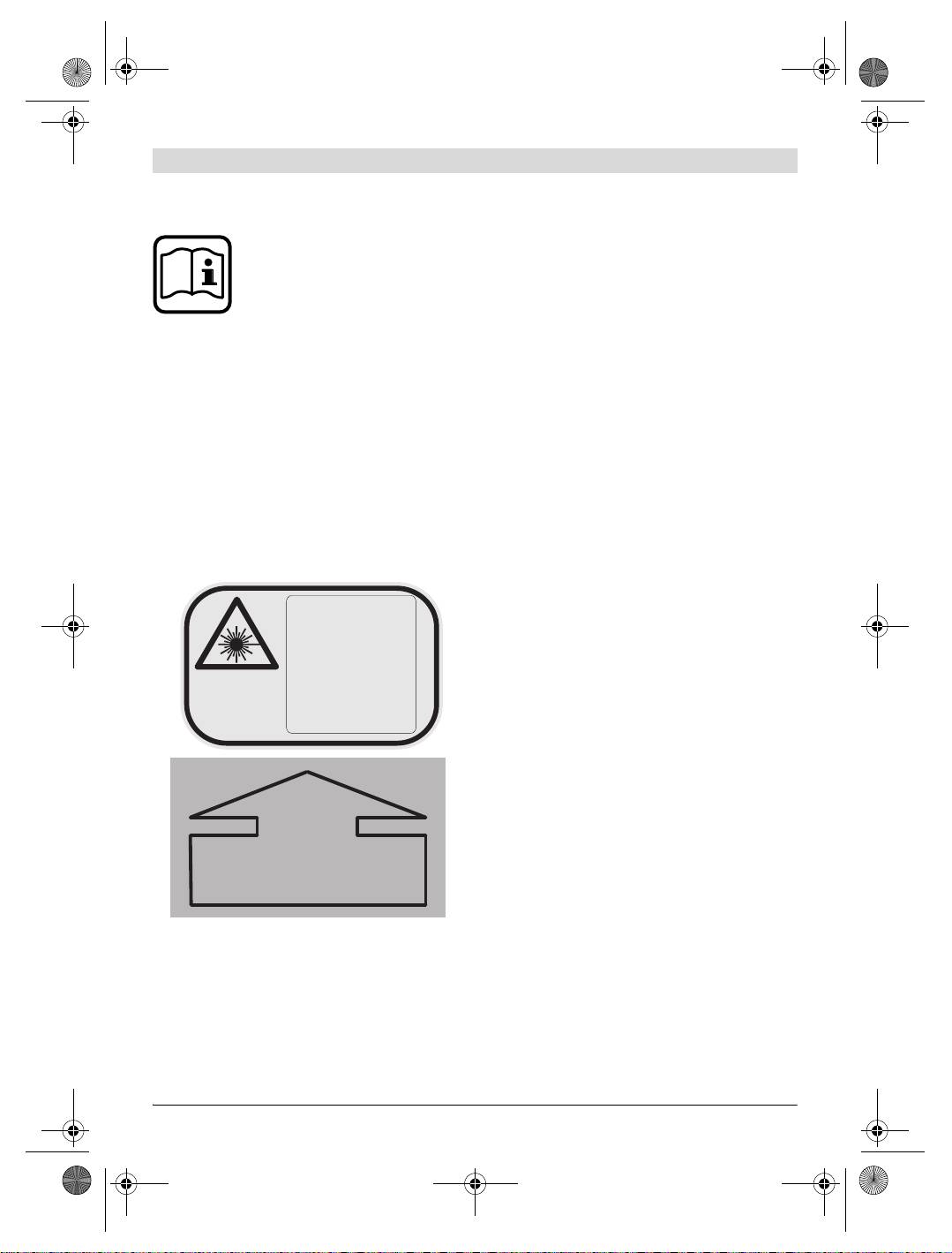
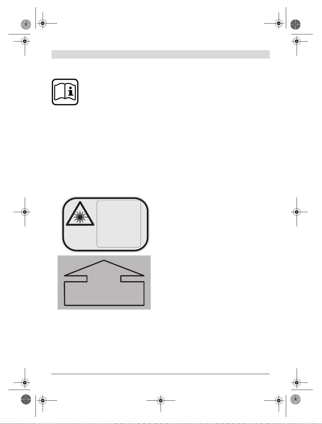
f The measuring tool is delivered with two
f Have the measuring tool repaired only
warning labels in German language (marked
through qualified specialists using original
with the number 16 and 4 in the representa-
spare parts. This ensures that the safety of
tion of the measuring tool on the graphic
the measuring tool is maintained.
page):
f Do not allow children to use the measuring
tool without supervision. They could unin-
LASER-
tentionally direct the laser beam toward per-
STRAHLUNG
sons or animals and cause damage to their
Direkte Bestrah-
eyes.
lung der Augen
vermeiden
f Avoid reflection of the laser beam on
DIN EN 60825-1:
2003-10,
smooth surfaces such as windows or mir-
Laser Klasse 3R
<5 mW,
rors. A reflected laser beam can also cause
635 nm
damage to the eye.
f The measuring tool should be operated only
by persons that are familiar with the han-
dling of laser devices. According to
EN 60825-1, this includes, among other
things, the knowledge about the bioligical ef-
fects of the laser to the eyes and the skin as
AUSTRITTSÖFFNUNG
well as the correct usage of laser protection
FÜR
devices in order to avoid dangers.
LASERSTRAHLUNG
f Keep the battery charger away from rain or
moisture. Penetration of water in the battery
f
Before putting into operation for the first
charger increases the risk of an electric shock.
time, attach the supplied stickers in your na-
f Do not charge other batteries with the bat-
tional language over the German text on
tery charger. The battery charger is suitable
warning label
16
as well as the complete
only for charging the Bosch battery pack in-
warning label
4
with the corresponding la-
serted in the measuring tool. When charging
bels in your national language. The stickers
other batteries, danger of fire and explosion
are supplied together with the measuring
is given.
tool.
1 609 929 L80 | (26.7.07) Bosch Power Tools
OBJ_BUCH-78-004.book Page 23 Thursday, July 26, 2007 2:04 PM
English | 23
f Keep the battery charger clean. Contamina-
8 Plumb beam
tion can lead to danger of an electric shock.
9 Variable laser beam
f Before each use, check the battery charger,
10 Plumb notches, X-axis
cable and plug. If damage is detected, do
11 Plumb notches, Y-axis
not use the battery charger. Never open the
battery charger yourself. Have repairs per-
12 Latch of battery lid
formed only by a qualified technician and
13 Battery lid
only using original spare parts. Damaged
14 Rubber foot
battery chargers, cables and plugs increase
15 Battery pack
the risk of an electric shock.
16 Laser warning label
f Do not operate the battery charger on easily
17 Tripod mount, 5/8" (horizontal and vertical)
inflammable surfaces (e.g., paper, textiles,
etc.) or surroundings. The heating of the bat-
18 Serial number
tery charger during the charging process can
19 Pushbutton for line operation and line
pose a fire hazard.
length selection
f Under abusive conditions, liquid may be
20 Upper direction pushbutton
ejected from the battery; avoid contact. If
21 Left direction pushbutton
contact accidentally occurs, flush with wa-
22 Pushbutton for rotational operation and
ter. If liquid contacts eyes, additionally
selection of the rotation speed
seek medical help. Liquid ejected from the
23 Lower direction pushbutton
battery may cause irritations or burns.
24 Right direction pushbutton
25 Manual levelling indicator “man”
26 Automatic levelling indicator “auto”
Functional Description
27 Battery charge control indicator
Please unfold the fold-out page with the repre-
28 “man/auto” button for switching off the
sentation of the measuring tool and leave it un-
automatic levelling
folded while reading the operating instructions.
29 On/Off button
30 Construction laser measuring rod*
Intended Use
31 Laser viewing glasses
The measuring tool is intended for projecting
and checking precise horizontal partitions, verti-
32 Wall holder/alignment unit*
cal lines, building lines and plumb points, for
33 5/8" screw on wall holder*
both indoor and outdoor use.
34 Knob screw of the alignment unit*
35 Measurement plate with stand
Product Features
36 Ceiling measurement plate*
The numbering of the product features shown
37 Inclination gauge*
refers to the illustration of the measuring tool
38 High-performance receiver with holder
on the graphic page.
39 Remote control
1 Spirit level
2 Reception lens for remote control
40 Tripod*
3 Socket for charge plug
41 Charge connector
4 Warning label, laser radiation exit opening
42 Battery charger
5 Exit opening for laser beam
43 Case
6 Y-axis mark
*The accessories illustrated or described are not in-
7 X-axis mark
cluded as standard delivery.
Bosch Power Tools 1 609 929 L80 | (26.7.07)
OBJ_BUCH-78-004.book Page 24 Thursday, July 26, 2007 2:04 PM
24 | English
Technical Data
Laser Level BL 200 GC
Professional
Article number
3 601 K15 000
Working range (radius)
1)
– without receiver, approx.
75 m
– with receiver, approx.
200 m
Levelling accuracy
1) 2)
± 0.05 mm/m
Self-levelling range, typically
± 8% (±5°)
Levelling duration, typically
10 s
Rotational speed
600/200/50/10 rpm
Operating temperature
– 20 ... +50 °C
Storage temperature
– 20 ... +70 °C
Relative air humidity, max.
90 %
Laser class
3R
Laser type
635 nm, <5 mW
Laser beam
Ø at the exit opening, approx.
1)
8mm
Tripod mount (horizontal and vertical)
5/8"
Rechargeable batteries
4 x 1.2 V KR20 (D) (5000 mAh)
Batteries (alkali-manganese)
4x1.5VLR20(D)
Operating life time, approx.
– Rechargeable batteries
30 h
– Batteries (alkali-manganese)
40 h
Weight according to EPTA-Procedure 01/2003
3.0 kg
Dimensions
211 x 180 x 190 mm
Degree of protection
IP 66 (dust-proof and protected
against powerful water jets)
1) at 21 °C
2) alongside the axes
Please observe the article number on the type plate of your measuring tool. The trade names of the individual
measuring tools may vary.
The measuring tool can be clearly identified with the serial number 18 on the type plate.
1 609 929 L80 | (26.7.07) Bosch Power Tools
OBJ_BUCH-78-004.book Page 25 Thursday, July 26, 2007 2:04 PM
English | 25
Assembly
Replacing the Battery Pack
The supplied battery pack 15 can also be re-
placed against other rechargeable or alkali-man-
Charging/Replacing the Battery Pack
ganese batteries. Use only batteries or recharge-
Charging the Battery Pack
able batteries of the same brand and with the
Before using for the first time, charge the sup-
same capacity. Always replace all of the re-
plied battery pack 15. The battery pack can be
chargeable batteries/batteries together.
charged only when in the measuring tool and on-
To remove the battery pack, turn the latch of the
ly with the battery charger 42 intended for this
battery lid 12 to the position and take off the
purpose.
battery lid 13.
Insert the charge connector 41 of the battery
Insert either a new battery pack, batteries or
charger into the socket 3 and connect the bat-
other rechargeable batteries. When inserting,
tery charger to the power supply. The red indi-
pay attention to the correct polarity. As a pro-
cator on the battery charger lights up during the
tective measure against incorrect polarity, the
charge procedure. Charging an empty battery
battery pack 15 can be inserted only in one po-
pack requires approx. 7 hours.
sition into the battery compartment.
The charge procedure is ended automatically.
In case other rechargeable batteries/batteries
Therefore, disconnect the battery charger 42
are inserted incorrectly the measuring tool can-
from the power supply after the charging has
not be switched on. Remove and reinsert the
taken place. The battery charger 42 and the bat-
other batteries/rechargeable batteries ensuring
tery pack 15 are protected against overcharging.
correct polarity and wait for one minute until
A battery that is new or has not been used for a
switching the measuring tool on again.
longer period does not develop its full capacity
Reattach the battery lid 13 (only one position
until after approx. 5 charging/discharging cycles.
possible) and turn the latch 12 to the posi-
If the battery pack is empty, the measuring tool
tion.
can also be operated off of the battery charger
42 when connected to a power supply. Switch
A fuse ensures that only the battery pack 15 can
the measuring tool off, charge the battery pack
be charged in the measuring tool. Other re-
for approx. 10 min and then switch the measur-
chargeable batteries cannot be charged in the
ing tool on again with the battery charger con-
measuring tool.
nected.
f Remove the battery pack, other rechargea-
ble batteries or batteries from the measur-
Practical Advice on Protection of the
ing tool when not using it for long periods.
Battery Pack
When storing for extended periods, re-
Do not recharge the battery pack 15 after each
chargeable batteries/batteries can corrode
use, as this will reduce its capacity. Recharge
and discharge themselves.
the battery pack only when the battery charge
control indicator 27 flashes or lights up continu-
ously.
A considerably reduced operating period after
charging indicates that the battery pack is used
up and must be replaced.
Bosch Power Tools 1 609 929 L80 | (26.7.07)
OBJ_BUCH-78-004.book Page 26 Thursday, July 26, 2007 2:04 PM
26 | English
Operation
To switch on, press the On/Off pushbutton 29.
The laser immediately starts in rotational opera-
tion, while the automatic levelling begins at the
Initial Operation
same time (see “Working with Automatic Level-
f Avoid heavy impact or falling of the measur-
ling”). The indicators 25, 26 and 27 light up for
ing tool. After heavy exterior impact on the
three seconds. During further levelling, the auto-
measuring tool, an accuracy check should al-
matic levelling indicator “auto” 26 flashes twice
ways be carried out before continuing to
per second. When the levelling takes longer than
work (see “Levelling Accuracy”).
5 seconds, rotational operation is interrupted
and the laser flashes twice per second until lev-
f Do not subject the measuring tool to ex-
elling is completed.
treme temperatures or variations in tem-
perature. As an example, do not leave it in
With the operating mode pushbuttons 19 and
vehicles for longer periods. In case of large
22 as well as with the direction pushbuttons 20,
variations in temperature, allow the measur-
21, 23 and 24, the operating mode can already
ing tool to adjust to the ambient temperature
be set upon levelling-in (see “Operating
before putting it into operation.
Modes”
). In this case, the measuring tool runs
for 5 seconds in the selected operating mode
Setting Up the Measuring Tool
during the levelling to confirm the entry. After
the levelling, the function is continued in this
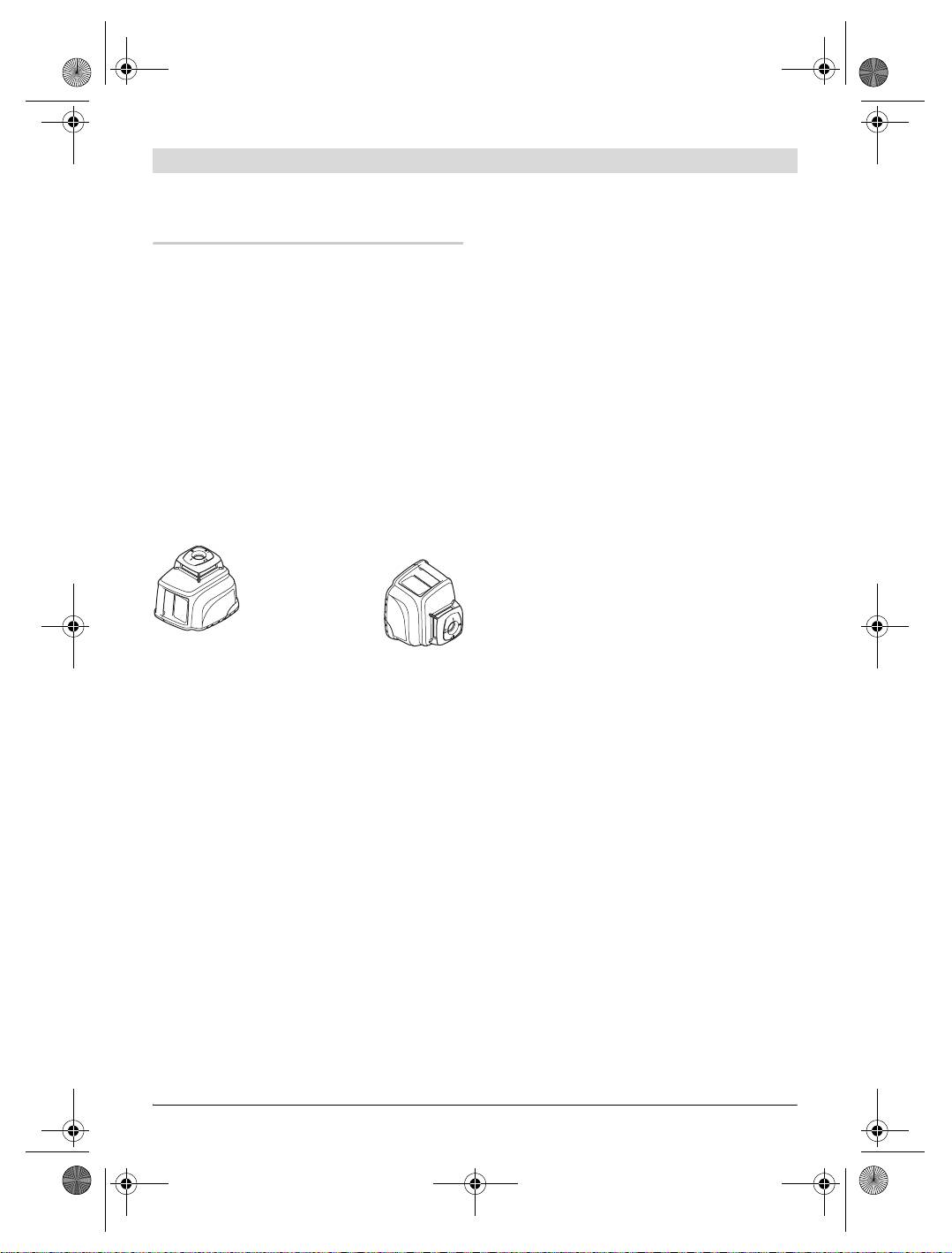
Horizontal posi-
operating mode.
tion
The measuring tool is levelled-in when the laser
beam and the “auto” indicator 26 light up con-
tinuously.
Vertical position
To switch off, press the On/Off 29 pushbutton
again.
Set up the measuring tool on a sturdy surface in
the horizontal or vertical position; mount it on a
The measuring tool automatically switches off
tripod 40 or to the wall holder with alignment
under the following conditions:
unit 32.
– When during automatic levelling, the measur-
Due to the high levelling accuracy, the measur-
ing tool is not within the self-levelling range
ing tool reacts sensitively to ground vibrations
for more than 10 minutes, the device switch-
and position changes. Therefore, pay attention
es off to save the batteries. Reposition the
that the position of the measuring tool is stable
measuring tool and switch on again.
in order to avoid operational interruptions due
– When exceeding the maximum permitted op-
to re-levelling.
erating temperature of 50 °C, the measuring
tool switches off to protect the laser diode.
Switching On and Off
After cooling down, the measuring tool is
ready for operation and can be switched on
f Do not direct the laser beam at persons
again.
or animals (especially not at their eye level)
and do not stare into the laser beam your-
– When the self-check fails or in case of mal-
self (not even from a distance). Immedi-
functions during operation, all functions are
ately after switching on, the measuring tool
blocked and the battery charge control indi-
emits the vertical plumb beam 8 and the var-
cator 27 flickers.
iable laser beam 9, which rotates around
– When the measuring tool is not switched on
the plumb beam. Special attention with the
again within 24 hours during activated stand
variable laser beam is required in point oper-
by operation.
ation.
– When the battery voltage is too low.
1 609 929 L80 | (26.7.07) Bosch Power Tools
OBJ_BUCH-78-004.book Page 27 Thursday, July 26, 2007 2:04 PM
English | 27
Stand-by-operation with Storage of the
Point Operation
Operating Mode
In this operating mode, the best
The measuring tool can be switched to stand by
visibility of the variable laser
for a maximum of 24 hours. When the automatic
beam is achieved. It is used, e.g.,
levelling was activated (“auto” indicator 26
for easy projecting of heights or
lights up continuously) prior to the beginning of
for checking building lines.
the stand by operation, the automatic levelling
Course of X- and Y-axis
continues to monitor the position of the measur-
The X- and Y-axis are at a right angle to each oth-
ing tool. The operating mode on the measuring
er, in accordance with the marks 7 and 6 on the
tool is retained.
housing. The marks are exactly above the plumb
To activate stand by operation, press the line
notches 10 (X-axis) and 11 (Y-axis) at the bot-
operation pushbutton 19 for at least 5 seconds.
tom edge of the housing.
In stand by, the laser beam and the levelling in-
dicators go out; only the battery charge control
indicator 27 flashes once every 5 seconds.
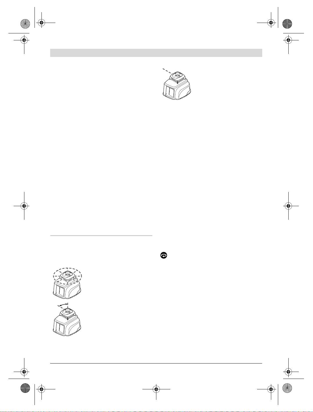
Making Use of the Operating Modes
To switch from stand by operation to normal op-
Turning the Rotational Plane in the
eration, press the line operation pushbutton 19
Vertical Position
again for at least 5 seconds. The measuring tool
When the measuring tool is in the vertical posi-
starts in the same operating mode as it was pri-
tion, the laser point, the laser line or the rota-
or to the stand by. When the position of the
tional plane can be rotated around the Y-axis for
measuring tool is changed as compared to the
basic sighting out or parallel alignment. For this,
starting position prior to stand by, the automat-
press the left 21 or right 24 direction pushbut-
ic levelling reacts as if the out-of-level safety
ton.
(see “Out-of-level Safety”) were activated: Ei-
Rotation is only possible within the self-levelling
ther the laser beam can be self-levelled to the
range (8 % to the left or right). When the meas-
same height as before the stand by or the laser
uring tool reaches the limit of this range, a warn-
beam is switched off as a protective measure
ing signal sounds, the laser and the “man” 25
against vertical errors.
and “auto” 26 indicators flash once per second.
Either press the opposite direction pushbutton
Operating Modes
(21 or 24), or switch the measuring tool off in
order to reposition it.
Overview
All three operating modes are possible with the
Rotational Operation
measuring tool in horizontal and vertical position.
After switching on, the measuring tool is in rota-
Rotational Operation
tional operation. It starts with the highest rota-
Rotational operation is especial-
tional speed.
ly recommended when working
By pressing the pushbutton for rotational oper-
with the receiver 38. Four differ-
ation 22, the speed can be reduced to a stand-
ent rotation speeds can be se-
still (point operation) in four steps. Repeated
lected.
pressing of the pushbutton 22 starts the rota-
Line Operation
tional operation again at the highest speed.
In this operating mode, the varia-
When working with the receiver 38, it is recom-
ble laser beam moves within a
mended to select the highest rotational speed.
defined aperture angle. This in-
When working without the receiver, reduce the
creases the visibility of the laser
rotational speed for improved visibility of the la-
beam as when compared to rota-
ser beam or use the laser viewing glasses 31 (ac-
tional operation. Four different
cessory).
aperture angles are available.
Bosch Power Tools 1 609 929 L80 | (26.7.07)
OBJ_BUCH-78-004.book Page 28 Thursday, July 26, 2007 2:04 PM
28 | English
When the measuring tool is in the vertical posi-
starts with point operation. Exception: The
tion and set to automatic levelling, it is possible
measuring tool was already in point opera-
to rotate the rotational plane around the X-axis by
tion by having pressed the pushbutton for ro-
pressing the upper 20 or lower 23 direction push-
tational operation 22. In this case, line oper-
button. Five seconds after last pressing on either
ation immediately starts with the smallest
of the four direction pushbuttons, the rotation
aperture angle upon pressing the pushbut-
plane is automatically levelled-in vertical again.
ton for line operation.
– When the measuring tool is set to line opera-
Line Operation
tion and the pushbutton for rotational opera-
To switch to line operation, press the pushbutton
tion 22 is pressed, then the measuring tool
for line operation 19. Depending on the previous
also starts with point operation. Exception:
operating mode, the measuring tool switches to
The measuring tool was already in point op-
point operation or to the line operation with the
eration by having pressed the pushbutton for
smallest aperture angle. Repeated pressing of
line operation 19. In this case, rotational op-
the pushbutton 19 switches the measuring tool
eration immediately starts with the highest
via the smallest aperture angle of 4° to the 30°,
rotational speed upon pressing the pushbut-
60° and 180° aperture angles. At the same time,
ton for rotational operation.
the speed is increased with each step. When
pressing the pushbutton 19 again, the measuring
tool returns to point operation.
Changing the Aperture Angle: When the meas-
Working with Automatic Levelling
uring tool is in the horizontal position and set to
Overview
automatic levelling, it is possible to increase or
reduce the aperture angle by pressing the upper
After switching on, the measuring tool automat-
20 or lower 23 direction pushbutton. The speed
ically detects the horizontal or vertical position.
remains unchanged.
To change between the horizontal and vertical
Rotating the Aperture Angle: When the measur-
position, switch the measuring tool off, reposi-
ing tool is in the horizontal position and set to
tion it and switch on again.
automatic levelling or inclined operation in a sin-
After switching on, the measuring tool checks
gle axis, it is possible to rotate the laser line or
the horizontal and vertical position and auto-
the laser point by 360° in steps by pressing the
matically levels out any unevenness within the
left 21 or right 24 direction pushbuttons. When
self-levelling range of approx. 8 %
the measuring tool is in the vertical position
(
± 0.8 m/10 m).
and set to automatic levelling, the rotation is ac-
tuated by pressing the upper 20 or lower 23 di-
When the measuring tool, after switching it on
rection pushbuttons.
or after a position change, is out-of-level by
more than 8 %, levelling in is no longer possible.
As long as the out-of-level safety was not acti-
Point Operation
vated (see “Out-of-level Safety”), a slow-se-
Point operation can be switched on either by
quence warning signal sounds, the rotor is
pressing the pushbutton for rotational opera-
stopped, the laser beam and the “auto” 26
tion 22 or the pushbutton for line operation 19:
as well as the “man” 25 indicators flash once
– When the measuring tool is set to rotational
per second. In this case, switch the measuring
operation and the pushbutton for line opera-
tool off, realign it and then switch the measuring
tion 19 is pressed, then the measuring tool
tool on again.
1 609 929 L80 | (26.7.07) Bosch Power Tools
OBJ_BUCH-78-004.book Page 29 Thursday, July 26, 2007 2:04 PM
English | 29
Position Changes
Working without Automatic Levelling
When the measuring tool is levelled in, it contin-
uously checks the horizontal and vertical posi-
In order to operate the measuring tool in any in-
tion. Position changes of the measuring tool
clined position (see “Contouring Gradients”),
lead to the following reactions:
the automatic levelling can be switched off for
the X- and Y-axis.
Minor Position Changes
f Position changes of the measuring tool are
Minor position changes are compensated within
not detected when the automatic levelling
5 seconds. The selected operating mode is not
is switched off.
interrupted. During the re-levelling, the “auto”
indicator 26 flashes twice every second. This au-
Switching Off the Automatic Levelling in the
tomatically compensates ground vibrations at
Horizontal Position/Inclined Operation in a
the construction site or weather influences.
Single Axis
Major Positon Changes
When the measuring tool is in the horizontal po-
When the measuring tool cannot carry out the
sition, the automatic levelling for both axes is
levelling-in procedure within 5 seconds, the ro-
switched off by pressing the “man/auto” push-
tor is stopped, the laser beam and the “auto” in-
button 28 once. The “man” indicator 25 flashes
dicator 26 flash twice per second to avoid faulty
once per second.
measurements during the levelling process.
Repeated pressing of the “man/auto” pushbut-
ton 28 switches on the inclined operation in a
Out-of-level Safety
single axis. In inclined operation in a single axis,
The measuring tool has an out-of-level safety
the X-axis is levelled in automatically, but the Y-
feature. It precludes levelling in after height
axis is not. The “man” 25 and “auto” 26 indica-
changes exceeding 3 mm/m and thus prevents
tors flash once per second.
vertical errors. The out-of-level safety is
When pressing the “man/auto” pushbutton 28 a
switched on automatically 30 seconds after a
third time, the automatic levelling is switched
pushbutton is pressed or after a levelling proce-
on again for both axes. The “auto” indicator 26
dure. When the out-of-level safety is activated,
flashes (as long as the measuring tool is re-lev-
the “auto” indicator 26 flashes once every 4 sec-
elling) or lights up continuously (when the
onds.
measuring tool is levelled in).
After a position change, the measuring tool first
attempts to compensate the change. When the
Switching Off the Automatic Levelling in the
limit value 3 mm/m is exceeded upon re-level-
Vertical Position
ling, a fast-sequence warning signal sounds, the
When the measuring tool is in the vertical posi-
laser switches off and the “man” indicator 25
tion, the automatic levelling for both axes is
flashes twice every second. In this case, switch
switched off by pressing the “man/auto” push-
the measuring tool off and then on again. Then,
button 28 once. The “man” indicator 25 flashes
check and correct the height of the laser beam.
once per second.
Repeated pressing of the “man/auto” pushbut-
ton 28 switches the automatic levelling on
again. The “auto” indicator 26 flashes (as long
as the measuring tool is re-levelling) or lights up
continuously (when the measuring tool is lev-
elled in).
Bosch Power Tools 1 609 929 L80 | (26.7.07)
30 | English
Changing the Inclination of the Rotational
Plane
Levelling accuracy
When the automatic levelling is switched off, the
Influences on Accuracy
rotational plane (as well as the laser point or the
laser line) can be rotated around the X- or the
The ambient temperature has the greatest influ-
Y-axis with the direction pushbuttons. For this,
ence. Especially temperature differences occur-
the function of the four direction pushbuttons is
ring from the ground upward can divert the laser
independent of the horizontal or vertical position
beam.
of the measuring tool and of the operating mode.
The deviations play a role in excess of approx.
20 m measuring distance and can easily reach
A
two to four times the deviation at 100 m.
Because the largest difference in temperature
layers is close to the ground, the measuring tool
should always be mounted on a tripod when
measuring distances exceeding 20 m. If possi-
ble, also set up the measuring tool in the centre
of the work area.
Accuracy Check of the Measuring Tool
BL
200 GC
SS
IONAL
Apart from exterior influences, device-specific
PROFE
influences (such as heavy impact or falling
down) can lead to deviations. Therefore, check
the accuracy of the measuring tool each time be-
fore starting your work.
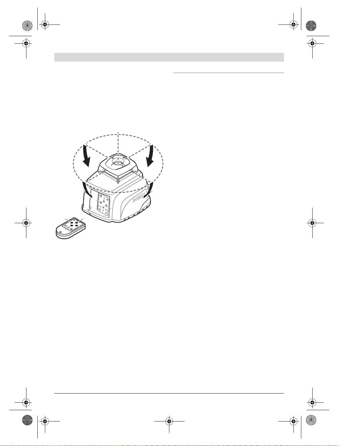
For the accuracy check, an unobstructed meas-
uring distance of 20 m on firm ground between
The rotational plane is rotated around the X-axis
two walls A and B is required. With the measur-
(directions A and C in the figure) with the upper
ing tool in the horizontal position, a
– transit
20 and lower 23 direction pushbuttons. The left
measurement is to be carried out across both
21 and right 24 direction pushbuttons rotate the
axes X and Y (both positive and negative) (alto-
rotational plane around the Y-axis (in directions
gether 4 complete measurements).
D and B in the figure).
– Mount the measuring tool in the horizontal
In inclined operation in a single axis (horizontal
position onto a tripod 40 (accessory) or
position), the rotational plane can be rotated
place it on a firm and level surface near
around the X-axis with the upper 20 and lower
wall A. Switch the measuring tool on.
23 direction pushbuttons; rotation around the
Y-axis is not possible.
1 609 929 L80 | (26.7.07) Bosch Power Tools
A
A
A
A
B
B
C
C
D
D
B
B
C
C
D
OBJ_BUCH-78-004.book Page 30 Thursday, July 26, 2007 2:04 PM
D
C
B
D
OBJ_BUCH-78-004.book Page 31 Thursday, July 26, 2007 2:04 PM
English | 31
– After levelling, direct the laser beam in point
– Without altering the height, turn the measur-
operation onto the close wall A. Mark the
ing tool around by 180°. Allow the measuring
centre point of the laser beam on the wall
tool to level in and mark the centre point of
(point I).
the laser beam on the wall A (point III).
– The difference d of both marked points I and
III on wall A amounts to the actual deviation
of the measuring tool for the measured axis.
Repeat the measuring procedure for the other
three axes. For this, turn the measuring tool pri-
or to each measuring procedure by 90°.
On the measuring distance of 2 x 20 = 40 m, the
maximum deviation may not exceed
± 2mm.
Consequently, the highest and lowest mark may
not be further apart than 4 mm (maximum).
– Turn the measuring tool around by 180°,
If the measuring tool should exceed the maxi-
allow it to level in and mark the centre point
mum deviation in anyone of the four measuring
of the laser beam on the opposite wall B
procedures, have it checked at a Bosch after-
(point II).
sales service agent.
– Without turning the measuring tool, position
it close to wall B. Switch the measuring tool
Operating Instructions
on and allow it to level in.
f Always use the centre of the laser point for
marking. The size of the laser point changes
with the distance.
Laser viewing glasses (Accessory)
The laser viewing glasses filter out the ambient
light. This makes the red light of the laser ap-
pear brighter for the eyes.
f Do not use the laser viewing glasses as safe-
ty goggles. The laser viewing glasses are used
for better recognition of the laser beam and
– Align the height of the measuring tool (using
thus do not protect against laser radiation.
the tripod or by underlaying, if required) in
f Do not use the laser viewing glasses as sun
such a manner that the centre point of the la-
glasses or in traffic. The laser viewing glass-
ser beam is projected exactly against the pre-
es do not afford complete UV protection and
viously marked point II on wall B.
reduce colour perception.
Bosch Power Tools 1 609 929 L80 | (26.7.07)
32 | English
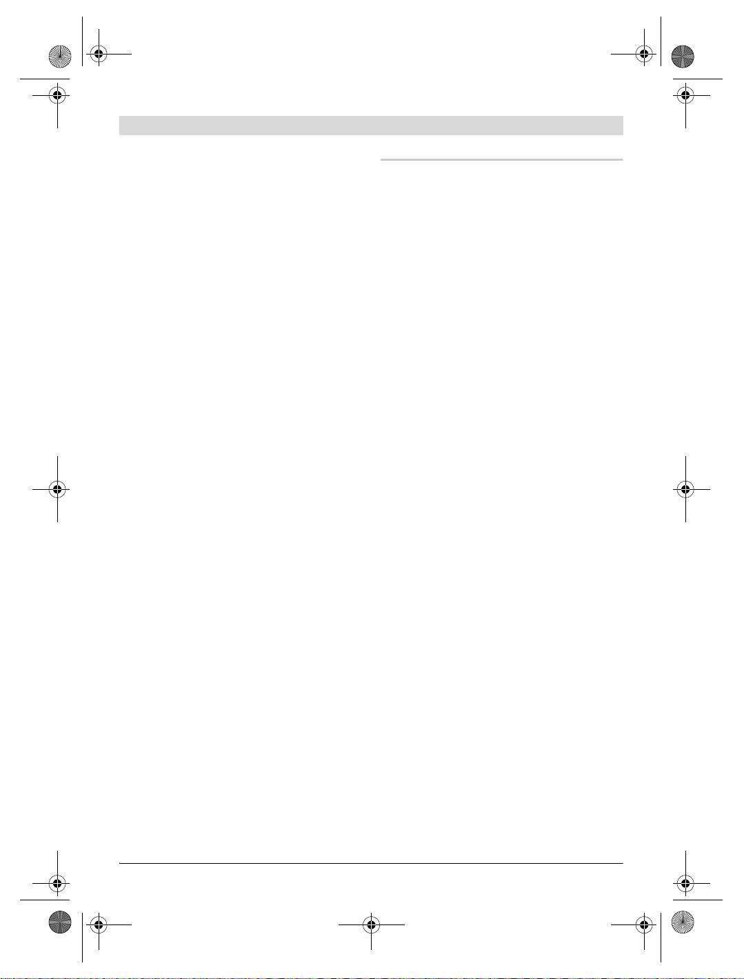
Working with the Remote Control
loosen the knob screws 34 on the alignment unit,
While pressing the operator pushbuttons, the
move the measuring tool to the required position
measuring tool can be brought out of alignment
and tighten the knob screws 34 again.
so that the rotation is briefly stopped. This effect
Working with the Measuring Plate
is avoided when using the remote control 39.
With the measuring plate 35, it is possible to
Receiving areas for the remote control are locat-
project the laser mark onto the floor or the laser
ed at the laser radiation outlet openings on four
height onto a wall.
sides of the measuring tool as well as next to the
socket for the charge plug 3.
The reception lens 2 at the bottom edge of the
housing reacts to the remote control signals
(typical working range: 200 m) with clearly in-
creased sensitivity. When using the remote con-
trol, set up the measuring tool in such a manner
that the signals of the remote control point di-
rectly at the reception lens 2.
With the zero field and the scale, the offset or
Working with the Tripod
drop to the required height can be measured
(Accessory)
and projected at another location. This elimi-
The measuring tool is equipped with two 5/8"
nates the necessity of precisely adjusting the
tripod mounts 17, one for horizontal and one for
measuring tool to the height to be projected.
vertical operation.
The measuring plate 35 has a reflective coating
On a tripod 40 with a measuring scale on the el-
that enhances the visibility of the laser beam at
evator column, the height difference can be ad-
greater distances or in intense sunlight. The
justed directly.
brightness intensification can be seen only
when viewing, parallel to the laser beam, onto
Working with Wall Holder/Alignment Unit
the measuring plate.
(Accessory) (see figure A)
The measuring tool can also be mounted to the
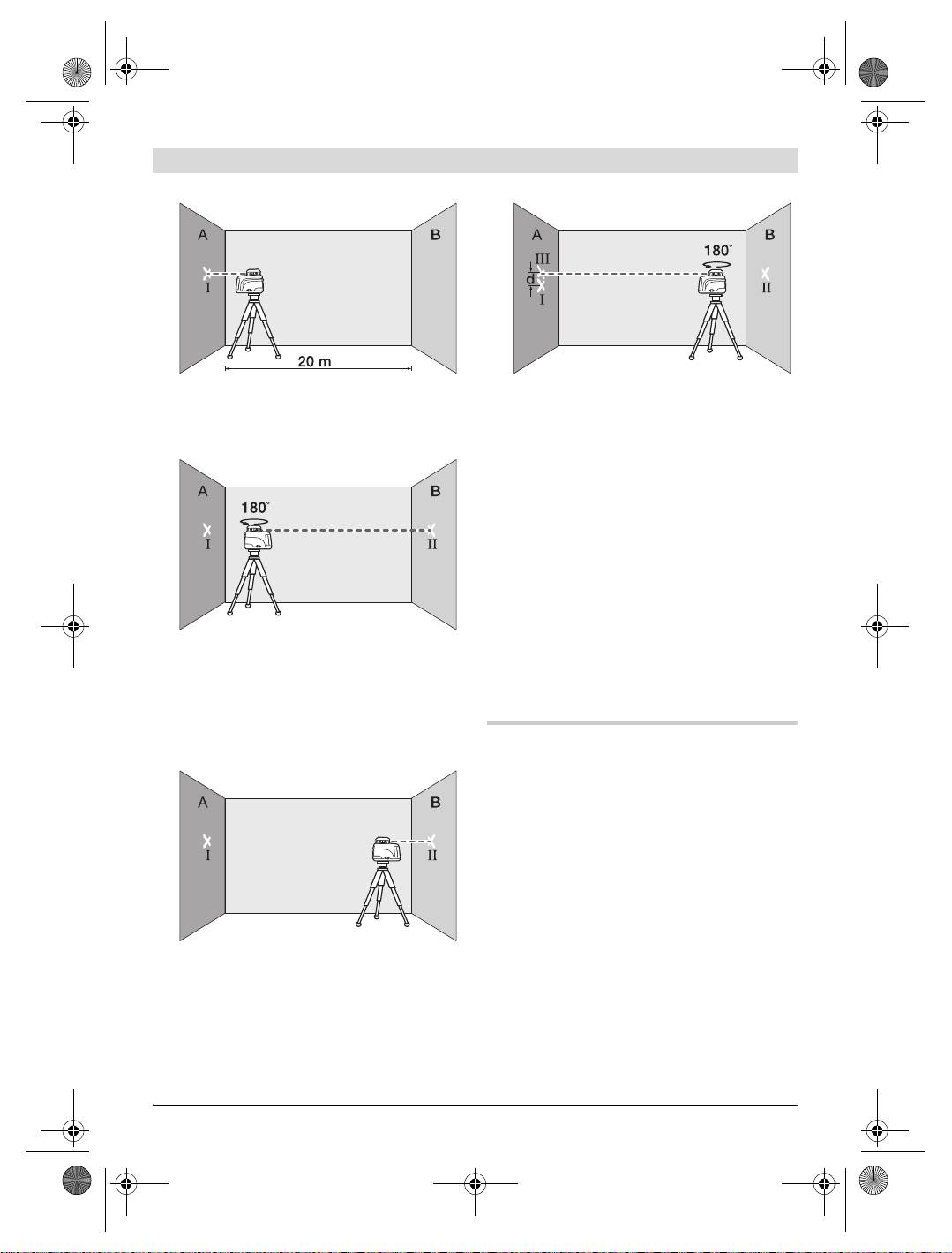
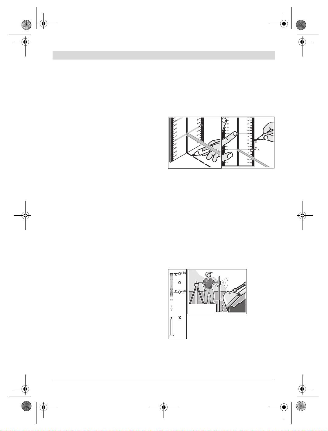
Working with the Measuring Rod (Accessory)
wall holder/alignment unit 32. For this, screw
For checking evenness or projecting gradients,
the 5/8" screw 33 of the wall holder into the tri-
it is recommended to use the measuring rod 30
pod mount 17 for horizontal operation of the
together with the receiver 38.
measuring tool.
Mounting to a wall: Mounting to a wall is recom-
mended, e.g., for work above the elevation
height of tripods or for work on unstable surfac-
es and without tripod. For this, fasten the wall
holder 32, with the measuring tool mounted, as
vertical as possible to a wall.
Mounting on a tripod: The wall holder 32 can al-
so be screwed onto a tripod with the tripod
mount on the back side. This method of fasten-
ing is especially recommended for work where
the rotational plane is to be aligned with a refer-
ence line.
A relative millimeter scale (
±50 cm) is marked on
With the alignment unit, it is possible to move the
the top of the measuring rod 30. Its zero height
mounted measuring tool vertically (when mount-
(90 to 210 cm) can be preset at the bottom of
ed to a wall) or horizontally (when mounted on a
the elevator column. This allows for direct read-
tripod) within a range of approx. 10 cm. For this,
ing of deviations from the specified height.
1 609 929 L80 | (26.7.07) Bosch Power Tools
30 mm
OBJ_BUCH-78-004.book Page 32 Thursday, July 26, 2007 2:04 PM
OBJ_BUCH-78-004.book Page 33 Thursday, July 26, 2007 2:04 PM
English | 33
Centring a Rotational Plane over a Floor Point
Work Examples
(see figure D)
Note: For all work examples, with the exception
When right angles are to be projected from a de-
of “Contouring Gradients”, it is assumed that
fined floor point, the rotational plane must be
the automatic levelling is switched on.
centred over this reference point.
Projecting Height Points (see figure B)
Set up the measuring tool in the vertical posi-
Position the measuring tool in the horizontal po-
tion as close as possible over the reference
sition onto a firm support or mount it onto a tri-
point and select point operation.
pod 40 (accessory).
Using the upper 20 and lower 23 direction push-
Working with tripod and receiver 38: In rotation-
buttons, rotate the variable laser beam in such a
al operation, align the laser beam to the re-
manner that it is pointed downward to the floor.
quired height and project the height at the tar-
With the spirit level 1 at the rotor head, align the
get location.
laser beam exactly vertical.
Working without tripod: Using the measuring
f Make sure that the variable laser beam is
plate 35, determine the height difference be-
pointed downward before viewing at the
tween the laser beam (in point or line opera-
spirit level 1 from above. This will avoid
tion) and the height line at the reference point.
looking directly into the laser beam.
Rotate the laser beam with the left 21 and right
Position the measuring tool in such a manner
24 direction pushbuttons to the target location
that the vertical laser beam precisely meets the
and project the measured height difference.
reference point.
Parallel Aligning of a Plumb Beam
Projecting Right Angles (see figure E)
(see figure C)
When the measuring tool is in the vertical posi-
When right angles are to be projected or when
tion, the right angle is indicated by means of the
partitions are to be aligned, the plumb beam 8
plumb beam 8 and the variable laser beam 9
.
must be aligned parallel, meaning at the same
If required, centre the rotational plane over a
distance to a reference line (e.g. a wall).
floor point and align the plumb beam 8 parallel
For this, set up the measuring tool in the vertical
to a reference line (e.g. a wall) in order to
position and position it in such a manner that
project right angles.
the plumb beam runs approximately parallel to
the reference line.
Marking Plumb Lines (see figure F)
For the exact positioning, measure the distance
Set up the measuring tool in the vertical posi-
between the plumb beam and the reference line
tion and align the variable laser beam 9 to the lo-
directly at the measuring tool, using the measur-
cation at which the plumb line is to be marked.
ing plate 35. Now, measure the distance again
Select line or rotational operation and mark the
between the plumb beam and the reference line
plumb line.
with the distance as far as possible away from
the measuring tool. Using the left 21 and right
Marking Vertical Planes (see figure F)
24 direction pushbuttons, align the plumb beam
Set up the measuring tool in the vertical posi-
in such a manner that it has the same distance
tion. Bring the variable laser into alignment with
to the reference line as measured directly at the
a reference line (e.g. a partition). Select line or
measuring tool.
rotational operation and mark the vertical plane.
Bosch Power Tools 1 609 929 L80 | (26.7.07)

OBJ_BUCH-78-004.book Page 34 Thursday, July 26, 2007 2:04 PM
34 | English
Parallel Aligning of a Rotational Plane
Contouring Gradients (see figure H)
(see figure G)
When contouring gradients, the automatic level-
When the measuring tool is in the vertical posi-
ling must be switched off (see “Working without
tion, the rotational plane can be aligned parallel
Automatic Levelling”). Afterwards, the measur-
to a reference line (e.g. a wall). For this, position
ing tool can be set up in any inclined position.
the measuring tool as close as possible to the ref-
When contouring gradients in only one axis di-
erence line and select rotational operation.
rection (e.g. hill flanks or slopes) and when the
Align the rotational plane approximately parallel
measuring tool is in the horizontal position, it is
to the reference line. For this, rotate the rota-
recommended to select inclined operation in a
tional plane around the Y-axis using the left 21
single axis
– (see “Switching Off the Automatic
and right 24 direction pushbuttons. For easier
Levelling in the Horizontal Position/Inclined Op-
alignment, the rotational plane can be brought
eration in a Single Axis”). In this case, align the
into proximity with the reference line. For this,
measuring tool with the Y-axis parallel to the di-
incline the rotational plane around the X-axis us-
rection of the incline or slope.
ing the upper 20 and lower 23 direction push-
buttons. Now, align the rotational plane exactly
For contouring of precise gradients, it is recom-
parallel to the reference line by rotating it
mended to use an inclination gauge 37 (acces-
around the Y-axis using the left 21 and right 24)
sory) which is mounted onto a tripod 40.
direction pushbuttons. When no direction push-
It is also possible to align the measuring tool
button is pressed for 5 seconds, the rotational
parallel to the required incline by underlaying on
plane is automatically aligned vertical again.
one side or with use of the tripod 40 (acces-
sory). Within the self-levelling range of 8 %,
Projecting Plumb Points to the Ceiling
inclines can also be adjusted with the direction
The plumb notches 10 and 11 are located at the
pushbutons.
bottom edge of the housing. They are used for
precise alignment of the plumb beam above a
floor point. Mark two right-angled auxiliary lines
through the floor point. Set up the measuring tool
in the horizontal position and bring it into align-
ment with the auxiliary lines using the plumb
notches.
Working with tripod: When the measuring tool is
in the horizontal position, the laser origin is locat-
ed directly above the horizontal tripod mount.
When using a tripod 40 (accessory), a plumb bob
can be attached to the tripod fastening screw and
used for alignment of the laser to the floor point.
1 609 929 L80 | (26.7.07) Bosch Power Tools
OBJ_BUCH-78-004.book Page 35 Thursday, July 26, 2007 2:04 PM
English | 35
Overview of Indications
Laser beam
Rotation
of the laser*
Warning
signal
Switching on the measuring tool (3 s self-check) zz zzz
Measuring tool levelled in/ready for operation zz z
Levelling in or re-levelling 2x/1 s 2x/1 s
Self-levelling range exceeded 1x/1 s 1x/1 s 1x/1 s 1x/1 s
Out-of-level shutoff activated 1x/4 s
Out-of-level shutoff actuated 4x/1 s 2x/1 s
Automatic levelling switched off 1x/1 s
Inclined operation in a single axis is switched on 1x/1 s 1x/1 s
Stand-by-operation with Storage of the
Operating Mode 1x/5 s
Battery voltage low 1x/2 s
Battery empty z
Malfunction z
* for line and rotational operation
1x/1 s
Flashing frequency (e.g. once per second)
z
Continuous operation
Function stopped
Maintenance and Service
If the measuring tool should fail despite the care
taken in manufacturing and testing procedures,
repair should be carried out by an authorized af-
Maintenance and Cleaning
ter-sales service centre for Bosch power tools.
Keep the measuring tool clean at all times.
In all correspondence and spare parts orders,
Wipe away debris or contamination with a dry,
please always include the 10-digit article
soft cloth. Do not use cleaning agents or solvents.
number given on the type plate of the measuring
tool.
Regularly clean the surfaces at the exit opening
of the laser in particular, and pay attention to
any fluff of fibres.
Spare Parts
When heavily contaminated, the measuring tool
Rubber foot 14 (3 pce.) . . . . . . . 1 609 203 588
can be cleaned under running water. Do not im-
merse the measuring tool in water and do not
Battery lid 13 . . . . . . . . . . . . . . 1 609 203 M02
subject it to a high-pressure water jet.
Battery pack 15 . . . . . . . . . . . . 1 609 203 M04
Bosch Power Tools 1 609 929 L80 | (26.7.07)
OBJ_BUCH-78-004.book Page 36 Thursday, July 26, 2007 2:04 PM
36 | English
After-sales service and
Disposal
customer assistance
Measuring tools, accessories and packaging
Our after-sales service responds to your ques-
should be sorted for environmental-friendly
tions concerning maintenance and repair of your
recycling.
product as well as spare parts. Exploded views
and information on spare parts can also be
Only for EC countries:
found under:
Do not dispose of measuring tools
www.bosch-pt.com
into household waste!
Our customer consultants answer your ques-
According the European Guideline
tions concerning best buy, application and ad-
2002/96/EC for Waste Electrical
justment of products and accessories.
and Electronic Equipment and its
implementation into national
Great Britain
right, measuring tools that are no longer usable
Robert Bosch Ltd. (B.S.C.)
must be collected separately and disposed of in
P.O. Box 98
an environmentally correct manner.
Broadwater Park
North Orbital Road
Battery packs/batteries:
Denham
Do not dispose of battery packs/batteries into
Uxbridge
household waste, fire or water. Battery packs/
UB 9 5HJ
batteries should be collected, recycled or dis-
Tel. Service: +44 (0844) 736 0109
posed of in an environmental-friendly manner.
Fax: +44 (0844) 736 0146
Only for EC countries:
E-Mail: SPT-Technical.de@de.bosch.com
Defective or dead out battery packs/batteries
Ireland
must be recycled according the guideline
Origo Ltd.
91/157/EEC.
Unit 23 Magna Drive
Batteries no longer suitable for use can be
Magna Business Park
directly returned at:
City West
Great Britain
Dublin 24
Tel. Service: +353 (01) 4 66 67 00
Robert Bosch Ltd. (B.S.C.)
Fax: +353 (01) 4 66 68 88
P.O. Box 98
Broadwater Park
Australia, New Zealand and Pacific Islands
North Orbital Road
Robert Bosch Australia Pty. Ltd.
Denham
Power Tools
Uxbridge
Locked Bag 66
UB 9 5HJ
Clayton South VIC 3169
Tel. Service: +44 (0844) 736 0109
Customer Contact Center
Fax: +44 (0844) 736 0146
Inside Australia:
E-Mail: SPT-Technical.de@de.bosch.com
Phone: +61 (01300) 307 044
Fax: + 61 (01300) 307 045
Subject to change without notice.
Inside New Zealand:
Phone: +64 (0800) 543 353
Fax: +64 (0800) 428 570
Outside AU and NZ:
Phone: +61 (03) 9541 5555
www.bosch.com.au
1 609 929 L80 | (26.7.07) Bosch Power Tools
OBJ_BUCH-78-004.book Page 37 Thursday, July 26, 2007 2:04 PM
Français | 37
fr
Consignes de sécurité
f Ne pas diriger le faisceau laser vers des per-
sonnes ou des animaux et ne jamais regar-
Lire toutes les instructions pour
der soi-même dans le faisceau laser. Cet ap-
travailler avec l’appareil de mesu-
pareil de mesure génère des rayons laser de
re sans risques et en toute sécuri-
la classe laser 3R suivant EN 60825-1. Regar-
té. S’assurer que les panneaux
der directement dans le faisceau laser
– mê-
d’avertissement se trouvant sur
me à partir d’une grande distance
– peut en-
l’appareil de mesure sont tou-
dommager les yeux.
jours lisibles. GARDER PRECIEUSEMENT CES
INSTRUCTIONS DE SECURITE.
f Ne pas utiliser les lunettes de vision du fais-
ceau laser en tant que lunettes de protec-
f Attention – si d’autres dispositifs d’utilisa-
tion. Les lunettes de vision du faisceau laser
tion ou d’ajustage que ceux indiqués ici
servent à mieux reconnaître le faisceau laser,
sont utilisés ou si d’autres procédés sont
elles ne protègent cependant pas du rayon-
appliqués, ceci peut entraîner une exposi-
nement laser.
tion au rayonnement dangereuse.
f Ne pas utiliser les lunettes de vision du fais-
f Cet appareil de mesure est fourni avec deux
ceau laser en tant que lunettes de soleil ou
plaques d’avertissement en langue alleman-
en circulation routière. Les lunettes de vi-
de (dans la représentation de l’appareil de
sion du faisceau laser ne protègent pas par-
mesure se trouvant sur la page des graphi-
faitement contre les rayons ultra-violets et
ques elles sont marquées du numéro 16
réduisent la perception des couleurs.
et 4) :
f Ne faire réparer l’appareil de mesure que
par une personne qualifiée et seulement
LASER-
avec des pièces de rechange d’origine. Ceci
STRAHLUNG
permet d’assurer la sécurité de l’appareil de
Direkte Bestrah-
mesure.
lung der Augen
f Ne pas laisser les enfants utiliser l’appareil
DIN EN 60825-1:
vermeiden
de mesure sans surveillance. Ils risqueraient
2003-10,
Laser Klasse 3R
<5 mW,
de diriger le faisceau laser vers des person-
635 nm
nes ou des animaux et endommager leurs
yeux.
f Eviter des réflexions du faisceau laser sur
les surfaces lisses telles que fenêtres ou mi-
roirs. Le faisceau laser réfléchi peut égale-
ment endommager les yeux.
f L’appareil de mesure ne devrait être utilisé
AUSTRITTSÖFFNUNG
que par des personnes familiarisées avec le
FÜR
maniement des appareils laser. Suivant
LASERSTRAHLUNG
EN 60825-1, ceci inclut une connaissance
des effets biologiques des faisceaux laser sur
f Avant la première mise en service, recou-
les yeux et sur la peau ainsi qu’une utilisation
vrir le texte allemand de la plaque d’avertis-
correcte des mesures de protection contre
sement 16 ainsi que la plaque d’avertisse-
les faisceaux laser afin d’éviter tout danger.
ment 4 par l’autocollant respectif dans
f Ne pas exposer le chargeur à la pluie ou à
votre langue. Les autocollants sont fournis
l’humidité. La pénétration d’eau dans un char-
avec l’appareil de mesure.
geur augmente le risque d’un choc électrique.
Bosch Power Tools 1 609 929 L80 | (26.7.07)
OBJ_BUCH-78-004.book Page 38 Thursday, July 26, 2007 2:04 PM
38 | Français
f Ne pas charger des accus d’une autre mar-
que avec le chargeur. Le chargeur n’est ap-
Eléments de l’appareil
proprié que pour charger le pack d’accus
La numérotation des éléments de l’appareil se
Bosch qui est introduit dans l’appareil de me-
réfère à la représentation de l’appareil de mesu-
sure. Lorsque des accus d’une autre marque
re sur la page graphique.
sont chargés, il y a risque d’incendie et d’ex-
1 Bulle d’air
plosion.
2 Lentille de réception pour télécommande
f Maintenir le chargeur propre. Un encrasse-
3 Douille pour fiche de charge
ment cause le risque de choc électrique.
4 Plaque d’avertissement orifice de sortie du
faisceau laser
f Avant toute utilisation, contrôler le char-
geur, la fiche et le câble. Ne pas utiliser le
5 Orifice de sortie du faisceau laser
chargeur si des défauts sont constatés. Ne
6 Repère sens Y
pas ouvrir le chargeur soi-même et ne le fai-
7 Repère sens X
re réparer que par une personne qualifiée
8 Rayon d’aplomb
et seulement avec des pièces de rechange
9 Faisceau laser variable
d’origine. Des chargeurs, câbles et fiches en-
10 Entaille d’aplomb sens X
dommagés augmentent le risque d’un choc
électrique.
11 Entaille d’aplomb sens Y
12 Blocage du couvercle du compartiment
f Ne pas utiliser le chargeur sur un support
à piles
facilement inflammable (tel que papier, tex-
13 Couvercle du compartiment à piles
tiles etc.) ou dans un environnement inflam-
mable. L’échauffement du chargeur lors du
14 Pied en caoutchouc
processus de charge augmente le risque d’in-
15 Pack d’accus
cendie.
16 Plaque d’avertissement de laser
f Dans de mauvaises conditions, du liquide
17 Raccord de trépied 5/8" (horizontal et
peut être éjecté de la batterie; éviter tout
vertical)
contact. En cas de contact accidentel, net-
18 Numéro de série
toyer à l’eau. Si le liquide entre en contact
19 Touche pour mode traçage de lignes et
avec les yeux, rechercher en plus une aide
choix de la longueur de ligne
médicale. Le liquide éjecté des batteries
20 Touche direction vers le haut
peut causer des irritations ou des brûlures.
21 Touche direction à gauche
22 Touche pour mode de rotation et choix de la
vitesse de rotation
23 Touche direction vers le bas
Description du fonctionnement
24 Touche direction à droite
Dépliez le volet sur lequel l’appareil de mesure
25 Affichage nivellement manuel « man »
est représenté de manière graphique. Laissez le
26 Affichage nivellement automatique « auto »
volet déplié pendant la lecture de la présente
27 Voyant lumineux indiquant l’état de charge
notice d’utilisation.
de l’accu
28 Touche « man/auto » pour éteindre le
nivellement automatique
Utilisation conforme
29 Interrupteur Marche/Arrêt
L’appareil de mesure est conçu pour la détermi-
30 Platine de mesure du laser de chantier*
nation et le contrôle de tracés en hauteur parfai-
tement horizontaux, de lignes verticales, d’ali-
31 Lunettes de vision du faisceau laser
gnements et de points d’aplomb à l’intérieur et
32 Fixation murale/unité d’alignement*
à l’extérieur.
33 Vis 5/8" sur la fixation murale*
1 609 929 L80 | (26.7.07) Bosch Power Tools
OBJ_BUCH-78-004.book Page 39 Thursday, July 26, 2007 2:04 PM
Français | 39
34 Vis de l’unité d’alignement*
40 Trépied*
35 Platine de mesure avec pied
41 Fiche de charge
36 Platine de mesure de plafond*
42 Chargeur
37 Cale d’inclinaison*
43 Coffre
38 Récepteur performant avec fixation
*Les accessoires décrits ou montrés ne sont pas com-
39 Télécommande
pris dans l’emballage standard.
Caractéristiques techniques
Laser de chantier BL 200 GC
Professional
N° d’article
3 601 K15 000
Zone de travail (radius)
1)
– sans récepteur env.
75 m
– avec récepteur env.
200 m
Précision de nivellement
1) 2)
± 0,05 mm/m
Plage typique de nivellement automatique
± 8% (±5°)
Temps typique de nivellement
10 s
Vitesse de rotation
600/200/50/10 tr/min
Température de service
– 20 ... +50 °C
Température de stockage
– 20 ... +70 °C
Humidité relative de l’air max.
90 %
Classe laser
3R
Type de laser
635 nm, <5 mW
Ø Faisceau laser à l’orifice de sortie env.
1)
8mm
Raccord de trépied (horizontal et vertical)
5/8"
Accus
4 x 1,2 V KR20 (D) (5000 mAh)
Piles (alcalines au manganèse)
4x1,5VLR20(D)
Durée de service env.
– Accus
30 h
– Piles (alcalines au manganèse)
40 h
Poids suivant EPTA-Procédure 01/2003
3,0 kg
Dimensions
211 x 180 x 190 mm
Type de protection
IP 66 (étanche à la poussière
et aux projections d’eau)
1) dans 21 °C
2) le long des axes
Faire attention au numéro d’article se trouvant sur la plaque signalétique de l’appareil de mesure. Les désigna-
tions commerciales des différents appareils peuvent varier.
Pour permettre une identification précise de votre appareil de mesure, le numéro de série 18 est marqué sur
la plaque signalétique.
Bosch Power Tools 1 609 929 L80 | (26.7.07)
OBJ_BUCH-78-004.book Page 40 Thursday, July 26, 2007 2:04 PM
40 | Français
Montage
ser que des piles ou accus du même fabricant et
avec la même capacité. Remplacer toujours tou-
tes les piles ou tous les accus à la fois.
Remplacer/charger le pack d’accus
Pour retirer le pack d’accus, tourner le blocage
Charger le pack d’accus
12 du couvercle du compartiment à piles dans la
Avant la première mise en service, charger le pack
position et enlever le couvercle du comparti-
d’accus 15 fourni avec l’appareil. Le pack d’accus
ment à piles 13.
ne peut être chargé que dans l’appareil de mesu-
Insérer soit un nouveau pack d’accus, soit des
re et avec le chargeur prévu à cet effet 42.
accus d’une autre marque ou des piles. Faire at-
Enfoncer la fiche de charge 41 du chargeur dans
tention à insérer les piles/accus en respectant la
la prise 3 et raccorder le chargeur au réseau. L’af-
polarité. Pour éviter que le pack d’accus 15 ne
fichage rouge sur le chargeur est allumé pendant
soit incorrectement inséré, il n’est possible de
le processus de charge. Le processus de charge
l’insérer que dans une seule position dans le
du pack d’accus déchargé dure 7 heures env.
compartiment à piles.
Le processus de charge ne s’arrête pas automa-
Au cas où des accus d’une autre marque ou des
tiquement. Une fois le processus de charge ter-
piles auraient été insérés dans le faux sens, l’ap-
miné, séparer le chargeur 42 du réseau. Le char-
pareil de mesure ne peut pas être mis en mar-
geur 42 et le pack d’accus 15 sont protégés
che. Respecter la polarité en insérant des accus
contre une surcharge.
d’une autre marque ou des piles et attendre
Un accu neuf ou un accu qui n’a pas été utilisé
pendant une minute avant de remettre l’appareil
pour une période assez longue n’atteint sa plei-
de mesure en marche.
ne puissance qu’après environ cinq cycles de
Placer le couvercle du compartiment à piles 13
charge et de décharge.
(une seule position est possible) et tourner le
Au cas où le pack d’accus serait déchargé, il est
blocage 12 dans la position .
possible de faire fonctionner l’appareil de mesu-
Un dispositif de sécurité assure que seul le pack
re par l’intermédiaire du chargeur 42 lorsque ce-
d’accus 15 peut être chargé dans l’appareil de
lui-ci est branché au réseau. Mettre l’appareil de
mesure. Les accus d’une autre marque doivent
mesure hors fonctionnement, charger le pack
être chargés en dehors de l’appareil de mesure.
d’accus pendant 10 minutes env. et remettre
l’appareil de mesure en marche, le chargeur y
f Retirer le pack d’accus, les accus d’une
étant connecté.
autre marque ou les piles de l’appareil de
mesure au cas où l’appareil ne serait pas
Indications relatives à la protection du pack
utilisé pour une période assez longue. En
d’accus
cas de stockage long, les accus ou les piles
Ne pas recharger le pack d’accus 15 après cha-
peuvent corroder ou se décharger.
que utilisation, ceci réduirait sa capacité. Ne
charger le pack d’accus que lorsque le voyant in-
diquant l’état de charge de l’accu 27 clignote ou
demeure allumé en permanence.
Fonctionnement
Si le temps de service de l’accu diminue consi-
dérablement après les recharges effectuées, ce-
Mise en service
la signifie que le pack d’accus est usagé et qu’il
doit être remplacé.
f Eviter les chocs ou les chutes de l’appareil
de mesure. Lorsque l’appareil de mesure a
Remplacer le pack d’accus
été soumis à de fortes influences extérieu-
Le pack d’accus 15 fourni avec l’appareil peut
res, toujours effectuer un contrôle de préci-
être remplacé par des accus d’une autre marque
sion avant de continuer à travailler (voir
ou par des piles alcalines au manganèse. N’utili-
« Précision de nivellement »).
1 609 929 L80 | (26.7.07) Bosch Power Tools
