Bosch GBH 5-40 DCE Professional: English
English: Bosch GBH 5-40 DCE Professional
English |
11
Bosch Power Tools
1 619 929 J15 | (6.4.11)
Nur für EU-Länder:
Gemäß der Europäischen Richtlinie
2002/96/EG über Elektro- und Elektronik-
Altgeräte und ihrer Umsetzung in nationales
Recht müssen nicht mehr gebrauchsfähige
Elektrowerkzeuge getrennt gesammelt und
einer umweltgerechten Wiederverwertung
zugeführt werden.
Änderungen vorbehalten.
English
Safety Notes
General Power Tool Safety Warnings
Read all safety warnings and all in-
structions.
Failure to follow the warnings
and instructions may result in electric shock, fire and/or seri-
ous injury.
Save all warnings and instructions for future reference.
The term “power tool” in the warnings refers to your mains-
operated (corded) power tool or battery-operated (cordless)
power tool.
Work area safety
f
Keep work area clean and well lit.
Cluttered or dark areas
invite accidents.
f
Do not operate power tools in explosive atmospheres,
such as in the presence of flammable liquids, gases or
dust.
Power tools create sparks which may ignite the dust
or fumes.
f
Keep children and bystanders away while operating a
power tool.
Distractions can cause you to lose control.
Electrical safety
f
Power tool plugs must match the outlet. Never modify
the plug in any way. Do not use any adapter plugs with
earthed (grounded) power tools.
Unmodified plugs and
matching outlets will reduce risk of electric shock.
f
Avoid body contact with earthed or grounded surfaces,
such as pipes, radiators, ranges and refrigerators.
There is an increased risk of electric shock if your body is
earthed or grounded.
f
Do not expose power tools to rain or wet conditions.
Water entering a power tool will increase the risk of electric
shock.
f
Do not abuse the cord. Never use the cord for carrying,
pulling or unplugging the power tool. Keep cord away
from heat, oil, sharp edges and moving parts.
Damaged
or entangled cords increase the risk of electric shock.
f
When operating a power tool outdoors, use an exten-
sion cord suitable for outdoor use.
Use of a cord suitable
for outdoor use reduces the risk of electric shock.
f
If operating a power tool in a damp location is unavoid-
able, use a residual current device (RCD) protected
supply.
Use of an RCD reduces the risk of electric shock.
Personal safety
f
Stay alert, watch what you are doing and use common
sense when operating a power tool. Do not use a power
tool while you are tired or under the influence of drugs,
alcohol or medication.
A moment of inattention while op-
erating power tools may result in serious personal injury.
f
Use personal protective equipment. Always wear eye
protection.
Protective equipment such as dust mask,
non-skid safety shoes, hard hat, or hearing protection
used for appropriate conditions will reduce personal inju-
ries.
f
Prevent unintentional starting. Ensure the switch is in
the off-position before connecting to power source
and/or battery pack, picking up or carrying the tool.
Carrying power tools with your finger on the switch or en-
ergising power tools that have the switch on invites acci-
dents.
f
Remove any adjusting key or wrench before turning
the power tool on.
A wrench or a key left attached to a ro-
tating part of the power tool may result in personal injury.
f
Do not overreach. Keep proper footing and balance at
all times.
This enables better control of the power tool in
unexpected situations.
f
Dress properly. Do not wear loose clothing or jewel-
lery. Keep your hair, clothing and gloves away from
moving parts.
Loose clothes, jewellery or long hair can be
caught in moving parts.
f
If devices are provided for the connection of dust ex-
traction and collection facilities, ensure these are con-
nected and properly used.
Use of dust collection can re-
duce dust-related hazards.
Power tool use and care
f
Do not force the power tool. Use the correct power tool
for your application.
The correct power tool will do the
job better and safer at the rate for which it was designed.
f
Do not use the power tool if the switch does not turn it
on and off.
Any power tool that cannot be controlled with
the switch is dangerous and must be repaired.
f
Disconnect the plug from the power source and/or the
battery pack from the power tool before making any
adjustments, changing accessories, or storing power
tools.
Such preventive safety measures reduce the risk of
starting the power tool accidentally.
f
Store idle power tools out of the reach of children and
do not allow persons unfamiliar with the power tool or
these instructions to operate the power tool.
Power
tools are dangerous in the hands of untrained users.
f
Maintain power tools. Check for misalignment or bind-
ing of moving parts, breakage of parts and any other
condition that may affect the power tool’s operation. If
damaged, have the power tool repaired before use.
Many accidents are caused by poorly maintained power
tools.
WARNING
OBJ_BUCH-491-006.book Page 11 Wednesday, April 6, 2011 4:45 PM
12
| English
1 619 929 J15 | (6.4.11)
Bosch Power Tools
f
Keep cutting tools sharp and clean.
Properly maintained
cutting tools with sharp cutting edges are less likely to bind
and are easier to control.
f
Use the power tool, accessories and tool bits etc. in ac-
cordance with these instructions, taking into account
the working conditions and the work to be performed.
Use of the power tool for operations different from those
intended could result in a hazardous situation.
Service
f
Have your power tool serviced by a qualified repair per-
son using only identical replacement parts.
This will en-
sure that the safety of the power tool is maintained.
Hammer Safety Warnings
f
Wear ear protectors.
Exposure to noise can cause hear-
ing loss.
f
Use auxiliary handle(s), if supplied with the tool.
Loss
of control can cause personal injury.
f
Hold power tool by insulated gripping surfaces, when
performing an operation where the cutting accessory
may contact hidden wiring or its own cord.
Cutting ac-
cessory contacting a “live” wire may make exposed metal
parts of the power tool “live” and could give the operator an
electric shock.
f
Use suitable detectors to determine if utility lines are
hidden in the work area or call the local utility company
for assistance.
Contact with electric lines can lead to fire
and electric shock. Damaging a gas line can lead to explo-
sion. Penetrating a water line causes property damage or
may cause an electric shock.
f
When working with the machine, always hold it firmly
with both hands and provide for a secure stance.
The
power tool is guided more secure with both hands.
f
Secure the workpiece.
A workpiece clamped with clamp-
ing devices or in a vice is held more secure than by hand.
f
Always wait until the machine has come to a complete
stop before placing it down.
The tool insert can jam and
lead to loss of control over the power tool.
Products sold in GB only
: Your product is fitted with a
BS 1363/A approved electric plug with internal fuse (ASTA
approved to BS 1362).
If the plug is not suitable for your socket outlets, it should be
cut off and an appropriate plug fitted in its place by an author-
ised customer service agent. The replacement plug should
have the same fuse rating as the original plug.
The severed plug must be disposed of to avoid a possible
shock hazard and should never be inserted into a mains sock-
et elsewhere.
Products sold in AUS and NZ only
: Use a residual current de-
vice (RCD) with a rated residual current of 30 mA or less.
Product Description and
Specifications
Read all safety warnings and all instruc-
tions.
Failure to follow the warnings and in-
structions may result in electric shock, fire
and/or serious injury.
While reading the operating instructions, unfold the graphics
page for the machine and leave it open.
Intended Use
The machine is intended for hammer drilling in concrete,
brick and stone as well as for chiselling.
Product Features
The numbering of the product features refers to the illustra-
tion of the machine on the graphics page.
1
Dust protection cap
2
Locking sleeve
3
Mode selector switch
4
Vibration damper
5
On/Off switch
6
Handle (insulated gripping surface)
7
Thumbwheel for speed preselection/impact frequency
preselection
8
Service indicator
9
Stand-by indicator
10
Auxiliary handle (insulated gripping surface)
Accessories shown or described are not part of the standard deliv-
ery scope of the product. A complete overview of accessories can
be found in our accessories program.
Technical Data
Rotary Hammer
GBH 5-40 DCE
Professional
Article number
3 611 B64 0..
Rated power input
W
1150
Speed
min
-1
170 – 340
Impact rate
– Drilling mode
– Chiselling mode
min
-1
min
-1
1500 –2900
1500 –3050
Impact energy per stroke
according to EPTA-Procedure
05/2009
J
8.8
Chisel positions
12
Tool holder
SDS-max
Lubrication
Central permanent
lubrication
The values given are valid for a nominal voltage [U] of 230 V. For differ-
ent voltages and models for specific countries, these values can vary.
Please observe the article number on the type plate of your machine.
The trade names of the individual machines may vary.
OBJ_BUCH-491-006.book Page 12 Wednesday, April 6, 2011 4:45 PM
English |
13
Bosch Power Tools
1 619 929 J15 | (6.4.11)
Noise/Vibration Information
Measured sound values determined according to EN 60745.
Typically the A-weighted noise levels of the product are:
Sound pressure level 93 dB(A); Sound power level
104 dB(A). Uncertainty K =3 dB.
Wear hearing protection!
Vibration total values (triax vector sum) determined accord-
ing to EN 60745:
Hammer drilling into concrete: Vibration emission value
a
h
=10 m/s
2
, Uncertainty K=1.5 m/s
2
,
Chiselling: Vibration emission value a
h
=8 m/s
2
, Uncertainty
K=1.5 m/s
2
.
The vibration emission level given in this information sheet
has been measured in accordance with a standardised test
given in EN 60745 and may be used to compare one tool with
another. It may be used for a preliminary assessment of expo-
sure.
The declared vibration emission level represents the main ap-
plications of the tool. However if the tool is used for different
applications, with different accessories or poorly maintained,
the vibration emission may differ. This may significantly in-
crease the exposure level over the total working period.
An estimation of the level of exposure to vibration should also
take into account the times when the tool is switched off or
when it is running but not actually doing the job. This may sig-
nificantly reduce the exposure level over the total working pe-
riod.
Identify additional safety measures to protect the operator
from the effects of vibration such as: maintain the tool and the
accessories, keep the hands warm, organisation of work pat-
terns.
Declaration of Conformity
We declare under our sole responsibility that the product de-
scribed under “Technical Data” is in conformity with the fol-
lowing standards or standardization documents: EN 60745
according to the provisions of the directives 2004/108/EC,
2006/42/EC.
Technical file at:
Robert Bosch GmbH, PT/ESC,
D-70745 Leinfelden-Echterdingen
Robert Bosch GmbH, Power Tools Division
D-70745 Leinfelden-Echterdingen
Leinfelden, 23.04.2010
Assembly
f
Before any work on the machine itself, pull the mains
plug.
Auxiliary Handle
f
Operate your machine only with the auxiliary handle
10.
The auxiliary handle
10
can be set to any position for a secure
and low-fatigue working posture.
– Turn the bottom part of the auxiliary handle
10
in counter-
clockwise direction and swivel the auxiliary handle
10
to
the desired position. Then retighten the bottom part of the
auxiliary handle
10
by turning in clockwise direction.
Changing the Tool
With the SDS-max tool holder, simpler and easier tool chang-
ing is possible without additional aids.
The dust protection cap
1
largely prevents the entry of drilling
dust into the tool holder during operation. When inserting the
tool, take care that the dust protection cap
1
is not damaged.
f
A damaged dust protection cap should be changed im-
mediately. We recommend having this carried out by
an after-sales service.
Inserting (see figure A)
– Clean and lightly grease the shank end of the tool.
The red symbols (open lock and bars) on the locking sleeve
2
indicate that the tool holder is open.
– Insert the tool into the tool holder with a turning motion un-
til it is automatically locked. The locking sleeve automati-
cally snaps toward the front and the red ring is no longer
visible. This indicates that the tool holder is locked.
Removing (see figure B)
– Pull the locking sleeve
2
back until it engages. The red sym-
bols on the locking sleeve can now be seen again. The lock-
ing sleeve remains in this position and the tool can be re-
moved without having to hold the locking sleeve.
Dust/Chip Extraction
Dusts from materials such as lead-containing coatings, some
wood types, minerals and metal can be harmful to one’s
health. Touching or breathing-in the dusts can cause allergic
reactions and/or lead to respiratory infections of the user or
bystanders.
Certain dusts, such as oak or beech dust, are considered as
carcinogenic, especially in connection with wood-treatment
Max. drilling dia.
– Concrete (with twist drill)
– Concrete (with break-through
drill bit)
– Brickwork (with core bit)
mm
mm
mm
40
55
90
Weight according to
EPTA-Procedure 01/2003
kg
6.8
Protection class
/
II
Rotary Hammer
GBH 5-40 DCE
Professional
The values given are valid for a nominal voltage [U] of 230 V. For differ-
ent voltages and models for specific countries, these values can vary.
Please observe the article number on the type plate of your machine.
The trade names of the individual machines may vary.
Dr. Egbert Schneider
Senior Vice President
Engineering
Dr. Eckerhard Strötgen
Head of Product
Certification
OBJ_BUCH-491-006.book Page 13 Wednesday, April 6, 2011 4:45 PM
14
| English
1 619 929 J15 | (6.4.11)
Bosch Power Tools
additives (chromate, wood preservative). Materials contain-
ing asbestos may only be worked by specialists.
– Provide for good ventilation of the working place.
– It is recommended to wear a P2 filter-class respirator.
Observe the relevant regulations in your country for the mate-
rials to be worked.
Operation
Starting Operation
f
Observe correct mains voltage! The voltage of the pow-
er source must agree with the voltage specified on the
nameplate of the machine. Power tools marked with
230 V can also be operated with 220 V.
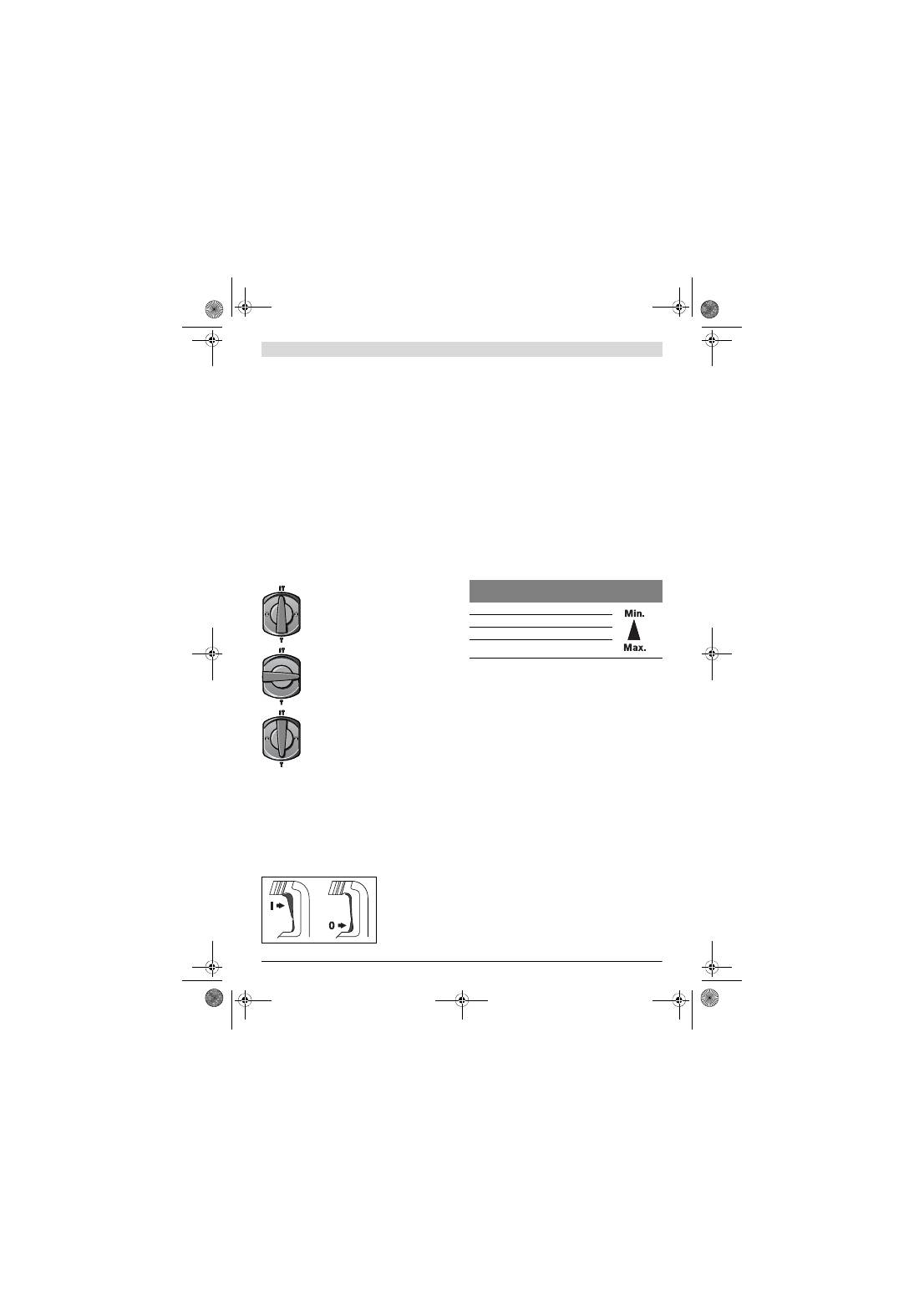
Setting the Operating Mode
The operating mode of the power tool is selected with the
mode selector switch
3
.
Note:
Change the operating mode only when the machine is
switched off! Otherwise, the machine can be damaged.
– Turn the mode selector switch
3
to the requested position.
In the “
chiselling
” position, the impact rate preselected with
the thumbwheel
7
is automatically increased when switching
on; this causes the power tool to operate with increased ca-
pacity when chiselling.
Switching On/Off in Drilling Mode
– To
start
the machine, press the On/Off switch
5
and keep
it pressed.
– To switch off the machine,
release
the On/Off switch
5
.
Switching On/Off in Chiselling Mode
– To
start
the machine, press the On/Off switch
5
at the top
(
I
) until it locks.
– To switch
off
the machine, press the On/Off switch
5
at the
bottom (
0
) and release it.
For low temperatures, the power tool reaches the full ham-
mer/impact capacity only after a certain time.
Setting the Speed/Impact Rate
The electronic control enables stepless speed and impact
preselection in accordance with the material to be worked.
The constant electronic control keeps the preselected speed
and impact rate nearly constant between no-load and load
conditions.
When plugging the plug into the socket outlet or after a power
failure, the constant electronic control automatically sets the
highest speed and impact rate. This ensures working at opti-
mum performance despite too low preadjustment of the
thumbwheel
7
.
– Select the impact rate with the thumbwheel
7
according to
the material.
The data in the following table are recommended values.
Safety Clutch
f
If the tool insert becomes caught or jammed, the drive
to the drill spindle is interrupted. Because of the forces
that occur, always hold the power tool firmly with both
hands and provide for a secure stance.
f
If the power tool jams, switch the machine off and loos-
en the tool insert. When switching the machine on with
the drilling tool jammed, high reaction torques can oc-
cur.
Changing the Chiselling Position (Vario-Lock)
The chisel can be locked in 12 positions. In this manner, the
optimum working position can be set for each application.
– Insert the chisel into the tool holder.
– Turn the mode selector switch
3
to the “Vario-Lock” posi-
tion (see “Setting the Operating Mode”, page 14).
– Turn the tool holder to the desired chiselling position.
– Turn the mode selector switch
3
to the “chiselling” posi-
tion. The tool holder is now locked.
f
The mode selector switch 3 must always be locked in
the “Chiselling” position when chiselling.
Position for
hammer drilling
When the drilling tool does not immediately
rotate upon switching on, allow the machine
to run slowly until the drilling tool rotates.
Vario-Lock
position for adjustment of the
chiselling position
Position for
chiselling
Application
Thumbwheel
Position
Working roughcast/light building materials
Removing tiles
Working brick
Working concrete
OBJ_BUCH-491-006.book Page 14 Wednesday, April 6, 2011 4:45 PM
English |
15
Bosch Power Tools
1 619 929 J15 | (6.4.11)
Working Advice
f
Before any work on the machine itself, pull the mains
plug.
Vibration Damper
The integrated vibration damper reduces occurring vibra-
tions.
The soft grip handle increases the safety against slipping off
and thus provides for a better grip and handling of the power
tool.
Maintenance and Service
Maintenance and Cleaning
f
Before any work on the machine itself, pull the mains
plug.
f
For safe and proper working, always keep the machine
and ventilation slots clean.
f
A damaged dust protection cap should be changed im-
mediately. We recommend having this carried out by
an after-sales service.
Service Indicator 8
When the carbon brushes are worn out, the machine switches
itself off. This is indicated approx. 8 hours beforehand by the
lighting or blinking of the service indicator
8
. The machine
must then be sent to an after-sales service agent. Addresses
are listed in the Section “After-sales Service and Customer
Assistance”.
Stand-by Indicator 9
When the mains plug is plugged in and mains voltage is given,
the stand-by indicator
9
must be lit. When the machine can-
not be switched on despite lit stand-by indicator
9
, it must be
sent to an after-sales service agent; for addresses, see sec-
tion “After-sales Service and Customer Assistance”, page 15.
If the machine should fail despite the care taken in manufac-
turing and testing procedures, repair should be carried out by
an after-sales service centre for Bosch power tools.
In all correspondence and spare parts order, please always in-
clude the 10-digit article number given on the type plate of
the machine.
After-sales Service and Customer Assistance
Our after-sales service responds to your questions concern-
ing maintenance and repair of your product as well as spare
parts. Exploded views and information on spare parts can al-
so be found under:
www.bosch-pt.com
Our customer service representatives can answer your ques-
tions concerning possible applications and adjustment of
products and accessories.
Great Britain
Robert Bosch Ltd. (B.S.C.)
P.O. Box 98
Broadwater Park
North Orbital Road
Denham
Uxbridge
UB 9 5HJ
Tel. Service: +44 (0844) 736 0109
Fax: +44 (0844) 736 0146
E-Mail: boschservicecentre@bosch.com
Ireland
Origo Ltd.
Unit 23 Magna Drive
Magna Business Park
City West
Dublin 24
Tel. Service: +353 (01) 4 66 67 00
Fax: +353 (01) 4 66 68 88
Australia, New Zealand and Pacific Islands
Robert Bosch Australia Pty. Ltd.
Power Tools
Locked Bag 66
Clayton South VIC 3169
Customer Contact Center
Inside Australia:
Phone: +61 (01300) 307 044
Fax: +61 (01300) 307 045
Inside New Zealand:
Phone: +64 (0800) 543 353
Fax: +64 (0800) 428 570
Outside AU and NZ:
Phone: +61 (03) 9541 5555
www.bosch.com.au
Republic of South Africa
Customer service
Hotline: +27 (011) 6 51 96 00
Gauteng – BSC Service Centre
35 Roper Street, New Centre
Johannesburg
Tel.: +27 (011) 4 93 93 75
Fax: +27 (011) 4 93 01 26
E-Mail: bsctools@icon.co.za
KZN – BSC Service Centre
Unit E, Almar Centre
143 Crompton Street
Pinetown
Tel.: +27 (031) 7 01 21 20
Fax: +27 (031) 7 01 24 46
E-Mail: bsc.dur@za.bosch.com
Western Cape – BSC Service Centre
Democracy Way, Prosperity Park
Milnerton
Tel.: +27 (021) 5 51 25 77
Fax: +27 (021) 5 51 32 23
E-Mail: bsc@zsd.co.za
OBJ_BUCH-491-006.book Page 15 Wednesday, April 6, 2011 4:45 PM
