Bosch AMC2 ENC-UL1 - Enclosure - Small: Connection of the Devices
Connection of the Devices: Bosch AMC2 ENC-UL1 - Enclosure - Small
8 en AEC-AMC2-UL1 - Installation manual
Connection of the Devices
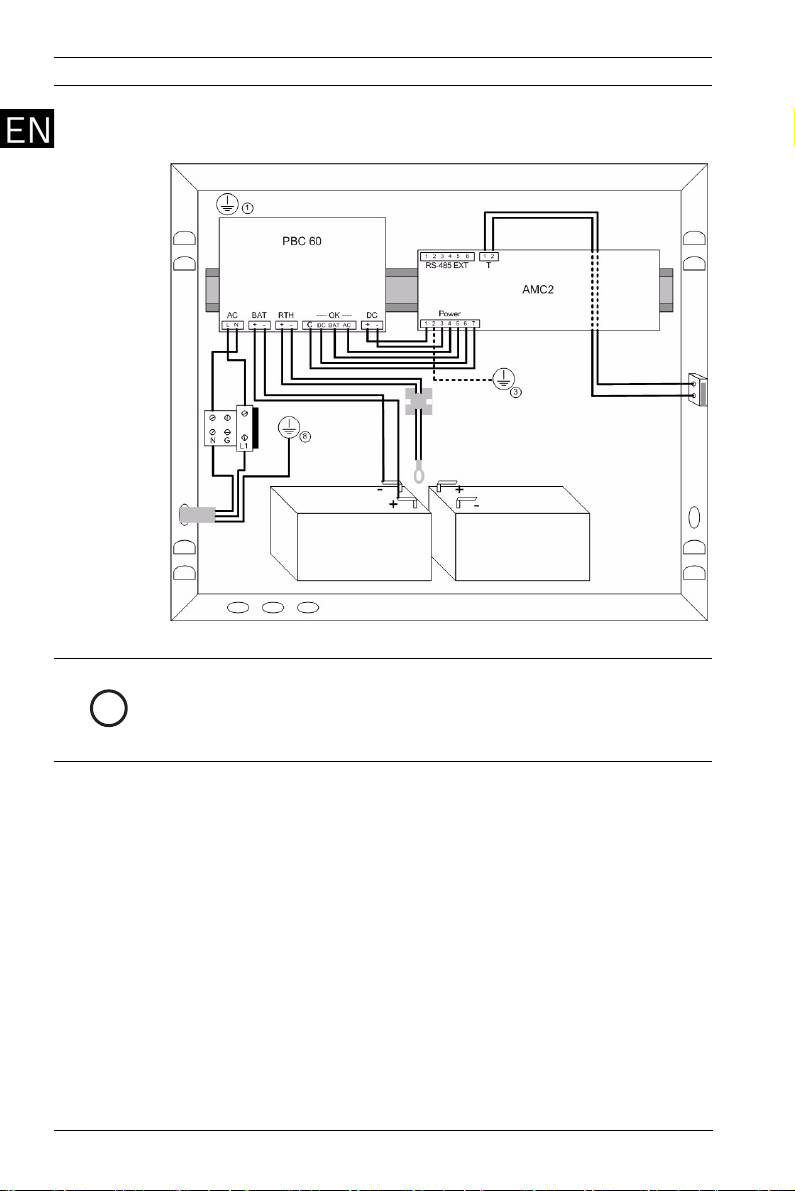
Figure 4 Connection of the devices
NOTICE!
The following steps describe connecting the rechargeable
i
batteries in 24 V mode. For information on 12 V mode
connections, refer to Section 12 V Mode Variations, page 11.
1. Mount the AMC on the rail (item 2 in Figure 1) and left
aside the power supply.
2. Put the rechargeable batteries on the bottom of the
housing and secure them with the cable ties F - (Figure 2).
3. Stick the bracket J (Figure 2) on the back of the housing in
such a way that later on not used connectors of the cable
B can fixed with it.
4. Cable set A:
a. Connect the 7-pin plug A1 to the AMC’s power supply
connector (labeled: POWER).
b. Attach connectors A3 to the PS-interface DC and A2
to the interface labeled OK.
c. Connect the grounding cable A4 beneath the
grounding point 3.
5. Cable set B:
F.01U.097.252 | V 3.2 | 2010.01 Bosch Sicherheitssysteme GmbH
AEC-AMC2-UL1 - Installation manual en 9
a. Connect the plug connector B1 the second position
from the left on the power supply - labeled with BAT.
b. Attach connector B2b (red) to the +-pin of the first
rechargeable battery.
c. With cable C connect the --pin of the first
rechargeable battery to the +-pin of the second
rechargeable battery.
d. Attach connector B2a (black) to the --pin of the
second rechargeable battery.
e. Connectors B3a and B3b are not used.
6. Cable set G:
a. Attach connector G1 on the PS-interface labbeled
RTH.
b. Route the cable across the temperature sensor
bracket so that the temperature sensor G2 hangs
approximitely 5 cm (2 in.) above the rechargeable
batteries.
7. Pre-assembled cable set 12:
a. Connect the 2-pin plug 13 on the interface AC of the
power supply.
8. Pre-assembled cable :
a. Connect the loose ends of the cover tamper switch to
the 2-pin screw connector on the top of the AMC.
Position the cable in the space between the housing
and the mounting rail.
DANGER!
Remove the fuse from the three-pin connector before
proceeding with the power supply connection.
Do not install the fuse before completing the installation
procedure.
9. Connect the main AC supply X:
a. Connect the brown (phase) wire to terminal L1.
b. Connect the blue (neutral) wire to terminal N.
c. Connect the grounding cable to the housing at
position 11.
CAUTION!
Shorten the external supply wires so that the ground (yellow/
green) wire is at least 20 mm (0.8 in.) longer than the live (blue
!
and brown) wires. This ensures that the ground wire cannot be
accidentally disconnected before life wires.
Bosch Sicherheitssysteme GmbH F.01U.097.252 | V 3.2 | 2010.01

10 en AEC-AMC2-UL1 - Installation manual
NOTICE!
Connect the readers and other peripheral devices as described
i
in the AMC Installation Manuals. Route the device cables
through the knock-outs in the top and right side wall of the
housing, or through the rear of the housing.
10. Cable D:
a. Connect D1 to grounding post 1.
b. Connect D2 to the grounding post on the cover.
11. Install the fuse.
12. Close the cover.
F.01U.097.252 | V 3.2 | 2010.01 Bosch Sicherheitssysteme GmbH
Оглавление
- English Deutsch Polski 中文 Nederlands Русский Magyar Português brasileiro Español latinoamericano Français
- Included parts
- Mounting the Housing
- Connection of the Devices
- 12 V Mode Variations
- Lieferumfang
- Montage des Gehäuses
- Anschaltung der Geräte
- 12V-Modus Varianten
- Elementy zestawu
- Montaż obudowy
- Podłączanie urządzeń
- Połączenia w trybie 12 V
- 附件
- 安装外壳
- 设备连接
- 12 V 模式
- Meegeleverde onderdelen
- Montage van de behuizing
- Aansluiten van de apparaten
- Varianten van de12 V-uitvoering
- Комплектация
- Монтаж корпуса
- Подключение устройств
- Режим 12 В
- Alkatrészekkel együtt
- A készülékház összeszerelése
- Az eszközök csatlakoztatása
- 12 V üzemmód változatok
- Partes incluídas
- Montar o gabinete
- Ligação dos dispositivos
- Variações do Modo de 12 V
- Piezas incluidas
- Montaje de la carcasa
- Conexión de los dispositivos
- Variaciones del modo de 12 V
- Pièces fournies
- Montage du caisson
- Raccordement des périphériques
- Variations en mode 12 V
