Bosch BCM 0000 A Battery Controller Module: English 4.998.137.261 Product description BCM 000 A
English 4.998.137.261 Product description BCM 000 A: Bosch BCM 0000 A Battery Controller Module
English 4.998.137.261 Product description BCM 000 A
15 / 32
ST - FIR / PRM1
4.998.153.971 / A5 / 06.2008
Functional description
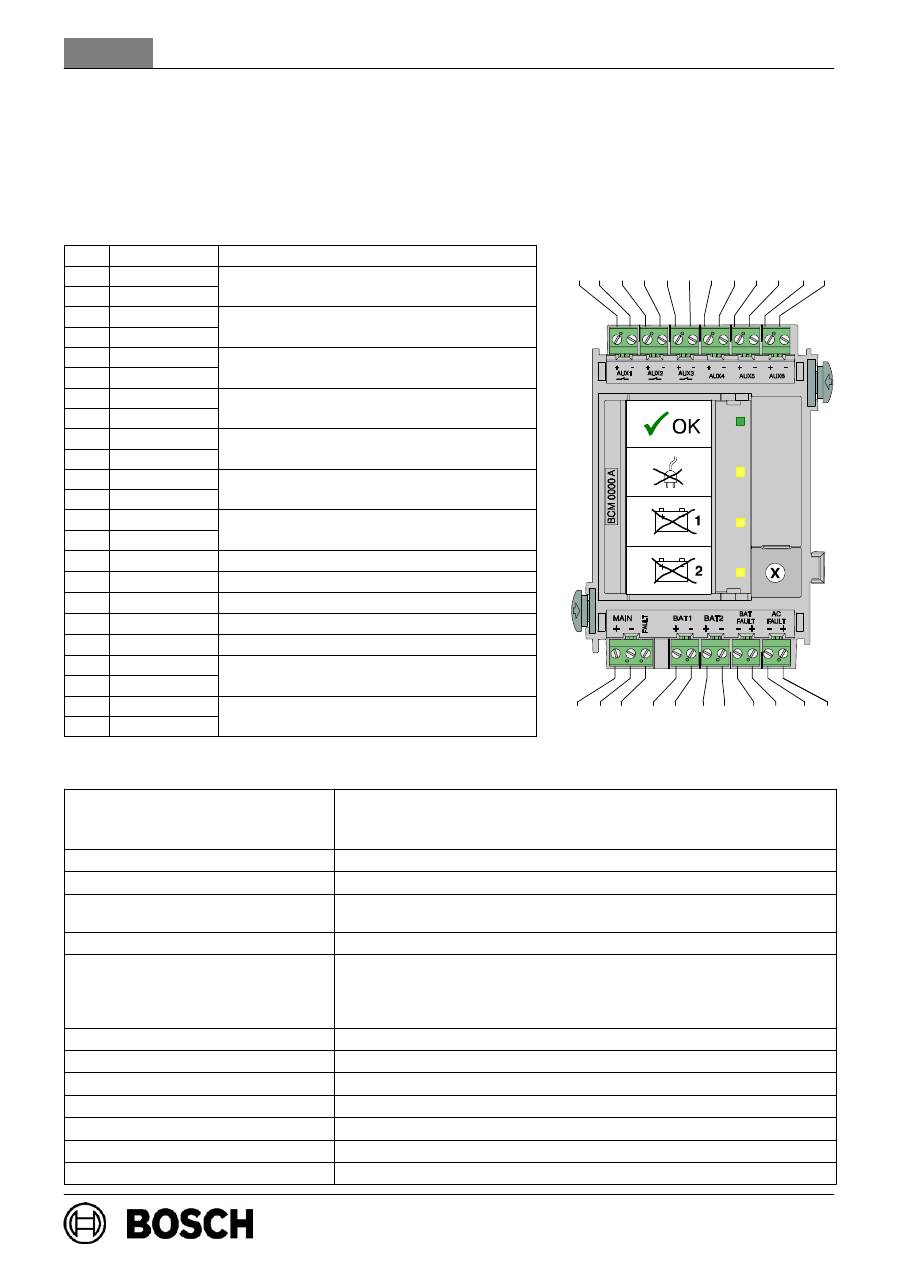
d The module monitores the complete panel power supply and controls temperature and time depending the battery charging. d The key enables the manual startup of the battery charging, e.g. if the battery voltage is less than 22 V and enables with charged batteries the panel startup without main power.
Wiring
Pos. Marking
Connection
1
AUX1 +
Switched output +24 V / max. 1.4 A
2
AUX1 -
Switched output +24 V / max. 1.4 A
(battery supported)
3
AUX2 +
Switched output +24 V / max. 1.4 A
4
AUX2 -
Switched output +24 V / max. 1.4 A
(battery supported)
5
AUX3 +
Switched output +24 V / max. 1.4 A
6
AUX3 -
Switched output +24 V / max. 1.4 A
(battery supported)
7
AUX4 +
Consumer, +24 V / max. 0.5 A
8
AUX4 -
Consumer, +24 V / max. 0.5 A
(battery supported)
9
AUX5 +
Consumer, +24 V / max. 0.5 A
10
AUX5 -
Consumer, +24 V / max. 0.5 A
(battery supported)
11
AUX6 +
Consumer, +24 V / max. 0.5 A
12
AUX6 -
Consumer, +24 V / max. 0.5 A
(battery supported)
13
MAIN +
Power Supply Unit
14
MAIN -
Power Supply Unit
15
FAULT
Main Power Fault Signal
17
BAT1 +
Batteries 1 + 2 plus
18
BAT1 -
Batteries 1 + 2 minus
19
BAT2 +
Batteries 3 + 4 plus
20
BAT2 -
Batteries 3 + 4 minus
21
BAT FAULT -
Battery Power Fault Signal
22
BAT FAULT +
Battery Power Fault Signal
23
AC FAULT -
Power Supply Unit Fault Signal Output
24
AC FAULT +
Power Supply Unit Fault Signal Output
Technical Specification
Indication / operating elements
1 LED green (Mains On)
3 LEDs yellow (Mains fault , Batteries 1 fault / Batteries 2 fault)
1 Key (Batteries charging, Panel startup without mains power)
Voltage supply
20 V DC - 30 V DC (min - max)
Current consumption at 24V DC
31 mA (Stand-by mode) / 40 mA (in case of malfunction)
Current supply of module rails
PRS 0002 / PRD 0004
Max. 6 A from Mains
Max. 8 A Battery power
Safety standards
IEC 60950 / EN 60950
Outputs
3 Switches (+24 V/1.4 A), battery supported
3 Consumer (+24 V/0.5 A), battery supported
1 Battery Power Fault Signal (0 V / 500 mA)
1 Power Supply Unit Fault Signal Output (0 V / 500 mA)
EMI / EMC protection
EN 50130-4 / EN 61000-6-3 / UL 864 / FCC Part 15
Permissible operating temperature
-5
_
C . . . 50
_
C
(23
_
F . . . 122
_
F)
Permissible storage temperature
-20
_
C . . . 60
_
C
(-4
_
F . . . 140
_
F)
Permissible relative humidity
max. 95 % non condensing
Housing material and color
ABS plastics, semi gloss anthrazit, RAL 7016
Dimensions (H x W x D)
approx. 127 x 96 x 60 mm (approx. 5.0 x 3.8 x 2.4 inches)
Weight
approx. 185 g (approx. 6.5 ounces)
1 2 3 4 5 6 7 8 9 10 11 12
13 14 15 17 18 19 20 21 22 23 24
Оглавление
- BCM 0000 A ⇒ PRS 0002 A / PRD 0004 A
- ⇔ ⇔
- Shqip 4.998.137.261 Përshkrimi i prodhimit BCM 0000 A
- Belgique/fr 4.998.137.261 Description de produit BCM 0000 A
- België/nl 4.998.137.261 Productbeschrijving BCM 0000 A
- Български 4.998.137.261 Описание на продукта BCM 0000 A
- Čzesky 4.998.137.261 Popis výrobku BCM 0000 A
- Deutsch 4.998.137.261 Produktbeschreibung BCM 0000 A
- Dansk 4.998.137.261 Produktbeskrivelse BCM 0000 A
- Español 4.998.137.261 Descripción del producto BCM 0000 A
- Eesti keel 4.998.137.261 Tootekirjeldus BCM 0000 A
- Suomi 4.998.137.261 Tuotekuvaus BCM 0000 A
- English 4.998.137.261 Product description BCM 000 A
- Ελληνικά 4.998.137.261 Περιγραφή προϊόντος BCM 0000 A
- Magyar 4.998.137.261 Termékleírás BCM 0000 A
- Hrvatski 4.998.137.261 Opis proizvoda BCM 0000 A
- Italiano 4.998.137.261 Descrizione prodotto BCM 0000 A
- Lietuviškai 4.998.137.261 Gaminio aprašymas BCM 0000 A
- Lativiski 4.998.137.261 Iekārtas apraksts BCM 0000 A
- Norsk 4.998.137.261 Produktbeskrivelse BCM 0000 A
- Nederlands 4.998.137.261 Productbeschrijving BCM 0000 A
- 4.998.137.261 Descrição do produto BCM 0000 A Português
- Polski 4.998.137.261 BCM 0000 A - opis produktu
- Română 4.998.137.261 Descriere produs BCM 0000 A
- Русский 4.998.137.261 Описание изделия BCM 0000 A
- Svenska 4.998.137.261 Produktbeskrivning för BCM 0000 A
- Srpski 4.998.137.261 Opis proizvoda BCM 0000 A
- Slovenščina 4.998.137.261 Opis izdelka BCM 0000 A
- Türkçe 4.998.137.261 Ürün tanm BCM 0000 A
- Bosch Sicherheitssysteme GmbHRobert-Koch-Straße 100D-85521 OttobrunnInfo-Servicewww.bosch-sicherheitssysteme.deinfo.service@de.bosch.com
