Bosch GWS 24-180 H Professional: English
English: Bosch GWS 24-180 H Professional
English | 15
Hinweise zur Statik
Schweiz
Schlitze in tragenden Wänden unterliegen der Norm
Tel.: (044) 8471511
DIN 1053 Teil 1 oder länderspezifischen Festlegungen.
Fax: (044) 8471551
Diese Vorschriften sind unbedingt einzuhalten. Ziehen Sie vor
E-Mail: Aftersales.Service@de.bosch.com
Arbeitsbeginn den verantwortlichen Statiker, Architekten
Luxemburg
oder die zuständige Bauleitung zurate.
Tel.: +32 2 588 0589
Fax: +32 2 588 0595
Wartung und Service
E-Mail: outillage.gereedschap@be.bosch.com
Wartung und Reinigung
Entsorgung
Ziehen Sie vor allen Arbeiten am Elektrowerkzeug den
Elektrowerkzeuge, Zubehör und Verpackungen sollen einer
Netzstecker aus der Steckdose.
umweltgerechten Wiederverwertung zugeführt werden.
Halten Sie das Elektrowerkzeug und die Lüftungs-
Werfen Sie Elektrowerkzeuge nicht in den Hausmüll!
schlitze sauber, um gut und sicher zu arbeiten.
Nur für EU-Länder:
Verwenden Sie bei extremen Einsatzbedingungen
Gemäß der Europäischen Richtlinie
nach Möglichkeit immer eine Absauganlage. Blasen Sie
2012/19/EU über Elektro- und Elektronik-
die Lüftungsschlitze häufig aus und schalten Sie einen
Altgeräte und ihrer Umsetzung in nationales
Fehlerstrom-(FI-)Schutzschalter vor. Bei der Bearbei-
Recht müssen nicht mehr gebrauchsfähige
tung von Metallen kann sich leitfähiger Staub im Innern des
Elektrowerkzeuge getrennt gesammelt und
Elektrowerkzeugs absetzen. Die Schutzisolierung des
einer umweltgerechten Wiederverwertung
Elektrowerkzeugs kann beeinträchtigt werden.
zugeführt werden.
Lagern und behandeln Sie das Zubehör sorgfältig.
Änderungen vorbehalten.
Wenn ein Ersatz der Anschlussleitung erforderlich ist, dann
ist dies von Bosch oder einer autorisierten Kundendienststel-
le für Bosch-Elektrowerkzeuge auszuführen, um Sicherheits-
gefährdungen zu vermeiden.
English
Kundendienst und Anwendungsberatung
Der Kundendienst beantwortet Ihre Fragen zu Reparatur und
Safety Notes
Wartung Ihres Produkts sowie zu Ersatzteilen. Explosions-
zeichnungen und Informationen zu Ersatzteilen finden Sie
General Power Tool Safety Warnings
auch unter:
Read all safety warnings and all in-
www.bosch-pt.com
structions. Failure to follow the warnings
Das Bosch-Anwendungsberatungs-Team hilft Ihnen gerne bei
and instructions may result in electric shock, fire and/or seri-
Fragen zu unseren Produkten und deren Zubehör.
ous injury.
www.powertool-portal.de, das Internetportal für Handwer-
Save all warnings and instructions for future reference.
ker und Heimwerker.
The term “power tool” in the warnings refers to your mains-
Geben Sie bei allen Rückfragen und Ersatzteilbestellungen
operated (corded) power tool or battery-operated (cordless)
bitte unbedingt die 10-stellige Sachnummer laut Typenschild
power tool.
des Elektrowerkzeuges an.
Deutschland
Work area safety
Robert Bosch GmbH
Keep work area clean and well lit. Cluttered or dark areas
Servicezentrum Elektrowerkzeuge
invite accidents.
Zur Luhne 2
Do not operate power tools in explosive atmospheres,
37589 Kalefeld – Willershausen
such as in the presence of flammable liquids, gases or
Unter www.bosch-pt.com können Sie online Ersatzteile be-
dust. Power tools create sparks which may ignite the dust
stellen oder Reparaturen anmelden.
or fumes.
Kundendienst: Tel.: (0711) 40040480
Keep children and bystanders away while operating a
Fax: (0711) 40040481
power tool. Distractions can cause you to lose control.
E-Mail: Servicezentrum.Elektrowerkzeuge@de.bosch.com
Electrical safety
Anwendungsberatung: Tel.: (0711) 40040480
Fax: (0711) 40040482
Power tool plugs must match the outlet. Never modify
E-Mail: Anwendungsberatung.pt@de.bosch.com
the plug in any way. Do not use any adapter plugs with
earthed (grounded) power tools. Unmodified plugs and
Österreich
matching outlets will reduce risk of electric shock.
Tel.: (01) 797222010
Avoid body contact with earthed or grounded surfaces,
Fax: (01) 797222011
such as pipes, radiators, ranges and refrigerators.
E-Mail: service.elektrowerkzeuge@at.bosch.com
Bosch Power Tools 1 609 92A 0B8 | (5.8.13)
WARNING
OBJ_BUCH-777-009.book Page 15 Monday, August 5, 2013 11:15 AM
OBJ_BUCH-777-009.book Page 16 Monday, August 5, 2013 11:15 AM
16 | English
There is an increased risk of electric shock if your body is
tools. Such preventive safety measures reduce the risk of
earthed or grounded.
starting the power tool accidentally.
Do not expose power tools to rain or wet conditions.
Store idle power tools out of the reach of children and
Water entering a power tool will increase the risk of electric
do not allow persons unfamiliar with the power tool or
shock.
these instructions to operate the power tool. Power
Do not abuse the cord. Never use the cord for carrying,
tools are dangerous in the hands of untrained users.
pulling or unplugging the power tool. Keep cord away
Maintain power tools. Check for misalignment or bind-
from heat, oil, sharp edges and moving parts. Damaged
ing of moving parts, breakage of parts and any other
or entangled cords increase the risk of electric shock.
condition that may affect the power tool’s operation. If
When operating a power tool outdoors, use an exten-
damaged, have the power tool repaired before use.
sion cord suitable for outdoor use. Use of a cord suitable
Many accidents are caused by poorly maintained power
for outdoor use reduces the risk of electric shock.
tools.
If operating a power tool in a damp location is unavoid-
Keep cutting tools sharp and clean. Properly maintained
able, use a residual current device (RCD) protected
cutting tools with sharp cutting edges are less likely to bind
supply. Use of an RCD reduces the risk of electric shock.
and are easier to control.
Use the power tool, accessories and tool bits etc. in ac-
Personal safety
cordance with these instructions, taking into account
Stay alert, watch what you are doing and use common
the working conditions and the work to be performed.
sense when operating a power tool. Do not use a power
Use of the power tool for operations different from those
tool while you are tired or under the influence of drugs,
intended could result in a hazardous situation.
alcohol or medication. A moment of inattention while op-
erating power tools may result in serious personal injury.
Service
Use personal protective equipment. Always wear eye
Have your power tool serviced by a qualified repair per-
protection. Protective equipment such as dust mask,
son using only identical replacement parts. This will en-
non-skid safety shoes, hard hat, or hearing protection
sure that the safety of the power tool is maintained.
used for appropriate conditions will reduce personal inju-
Safety Warnings for Angle Grinder
ries.
Prevent unintentional starting. Ensure the switch is in
Safety Warnings common for Grinding, Sanding,
the off-position before connecting to power source
Wire Brushing or Abrasive Cutting Off Operations
and/or battery pack, picking up or carrying the tool.
This power tool is intended to function as a grinder,
Carrying power tools with your finger on the switch or en-
sander, wire brush or cut-off tool. Read all safety warn-
ergising power tools that have the switch on invites acci-
ings, instructions, illustrations and specifications pro-
dents.
vided with this power tool. Failure to follow all instruc-
Remove any adjusting key or wrench before turning
tions listed below may result in electric shock, fire and/or
the power tool on. A wrench or a key left attached to a ro-
serious injury.
tating part of the power tool may result in personal injury.
Operations such as polishing are not recommended to
Do not overreach. Keep proper footing and balance at
be performed with this power tool. Operations for which
all times. This enables better control of the power tool in
the power tool was not designed may create a hazard and
unexpected situations.
cause personal injury.
Dress properly. Do not wear loose clothing or jewel-
Do not use accessories which are not specifically de-
lery. Keep your hair, clothing and gloves away from
signed and recommended by the tool manufacturer.
moving parts. Loose clothes, jewellery or long hair can be
Just because the accessory can be attached to your power
caught in moving parts.
tool, it does not assure safe operation.
If devices are provided for the connection of dust ex-
The rated speed of the accessory must be at least equal
traction and collection facilities, ensure these are con-
to the maximum speed marked on the power tool. Ac-
nected and properly used. Use of dust collection can re-
cessories running faster than their rated speed can break
duce dust-related hazards.
and fly apart.
The outside diameter and the thickness of your acces-
Power tool use and care
sory must be within the capacity rating of your power
Do not force the power tool. Use the correct power tool
tool. Incorrectly sized accessories cannot be adequately
for your application. The correct power tool will do the
guarded or controlled.
job better and safer at the rate for which it was designed.
Threaded mounting of accessories must match the
Do not use the power tool if the switch does not turn it
grinder spindle thread. For accessories mounted by
on and off. Any power tool that cannot be controlled with
flanges, the arbour hole of the accessory must fit the
the switch is dangerous and must be repaired.
locating diameter of the flange. Accessories that do not
Disconnect the plug from the power source and/or the
match the mounting hardware of the power tool will run out
battery pack from the power tool before making any
of balance, vibrate excessively and may cause loss of con-
adjustments, changing accessories, or storing power
trol.
1 609 92A 0B8 | (5.8.13) Bosch Power Tools

OBJ_BUCH-777-009.book Page 17 Monday, August 5, 2013 11:15 AM
English | 17
Do not use a damaged accessory. Before each use in-
For example, if an abrasive wheel is snagged or pinched by
spect the accessory such as abrasive wheels for chips
the workpiece, the edge of the wheel that is entering into
and cracks, backing pad for cracks, tear or excess
the pinch point can dig into the surface of the material
wear, wire brush for loose or cracked wires. If power
causing the wheel to climb out or kick out. The wheel may
tool or accessory is dropped, inspect for damage or in-
either jump toward or away from the operator, depending
stall an undamaged accessory. After inspecting and in-
on direction of the wheel’s movement at the point of pinch-
stalling an accessory, position yourself and bystanders
ing. Abrasive wheels may also break under these condi-
away from the plane of the rotating accessory and run
tions.
the power tool at maximum no-load speed for one min-
Kickback is the result of power tool misuse and/or incor-
ute. Damaged accessories will normally break apart during
rect operating procedures or conditions and can be avoid-
this test time.
ed by taking proper precautions as given below.
Wear personal protective equipment. Depending on
Maintain a firm grip on the power tool and position your
application, use face shield, safety goggles or safety
body and arm to allow you to resist kickback forces. Al-
glasses. As appropriate, wear dust mask, hearing pro-
ways use auxiliary handle, if provided, for maximum
tectors, gloves and shop apron capable of stopping
control over kickback or torque reaction during
small abrasive or workpiece fragments. The eye protec-
start-up. The operator can control torque reactions or
tion must be capable of stopping flying debris generated
kickback forces, if proper precautions are taken.
by various operations. The dust mask or respirator must be
Never place your hand near the rotating accessory. Ac-
capable of filtrating particles generated by your operation.
cessory may kickback over your hand.
Prolonged exposure to high intensity noise may cause
Do not position your body in the area where power tool
hearing loss.
will move if kickback occurs. Kickback will propel the
Keep bystanders a safe distance away from work area.
tool in direction opposite to the wheel’s movement at the
Anyone entering the work area must wear personal
point of snagging.
protective equipment. Fragments of workpiece or of a
Use special care when working corners, sharp edges,
broken accessory may fly away and cause injury beyond
etc. Avoid bouncing and snagging the accessory. Cor-
immediate area of operation.
ners, sharp edges or bouncing have a tendency to snag the
Hold the power tool by insulated gripping surfaces on-
rotating accessory and cause loss of control or kickback.
ly, when performing an operation where the cutting ac-
Do not attach a saw chain woodcarving blade or
cessory may contact hidden wiring or its own cord. Cut-
toothed saw blade. Such blades create frequent kickback
ting accessory contacting a “live” wire may make exposed
and loss of control.
metal parts of the power tool “live” and could give the op-
erator an electric shock.
Safety warnings specific for Grinding and Abrasive
Position the cord clear of the spinning accessory. If you
Cutting-Off operations
lose control, the cord may be cut or snagged and your hand
Use only wheel types that are recommended for your
or arm may be pulled into the spinning wheel.
power tool and the specific guard designed for the se-
lected wheel. Wheels for which the power tool was not de-
Never lay the power tool down until the accessory has
signed cannot be adequately guarded and are unsafe.
come to a complete stop. The spinning wheel may grab
the surface and pull the power tool out of your control.
The grinding surface of the centre depressed wheels
must be mounted below the plane of the guard lip. An
Do not run the power tool while carrying it at your side.
improperly mounted wheel that projects through the plane
Accidental contact with the spinning accessory could snag
of the guard lip cannot be adequately protected.
your clothing, pulling the accessory into your body.
The guard must be securely attached to the power tool
Regularly clean the power tool’s air vents. The motor’s
and positioned for maximum safety, so the least
fan will draw the dust inside the housing and excessive ac-
amount of wheel is exposed towards the operator. The
cumulation of powdered metal may cause electrical haz-
guard helps to protect operator from broken wheel frag-
ards.
ments, accidental contact with wheel and sparks that
Do not operate the power tool near flammable materi-
could ignite clothing.
als. Sparks could ignite these materials.
Wheels must be used only for recommended applica-
Do not use accessories that require liquid coolants. Us-
tions. For example: do not grind with the side of the
ing water or other liquid coolants may result in electrocu-
cut-off wheel. Abrasive cut-off wheels are intended for
tion or shock.
peripheral grinding; side forces applied to these wheels
Kickback and related warnings
may cause them to shatter.
Kickback is a sudden reaction to a pinched or snagged ro-
Always use undamaged wheel flanges that are of cor-
tating wheel, backing pad, brush or any other accessory.
rect size and shape for your selected wheel. Proper
Pinching or snagging causes rapid stalling of the rotating
wheel flanges support the wheel thus reducing the possi-
accessory which in turn causes the uncontrolled power
bility of wheel breakage. Flanges for cut-off wheels may be
tool to be forced in the direction opposite of the accesso-
different from grinding wheel flanges.
ry’s rotation at the point of the binding.
Bosch Power Tools 1 609 92A 0B8 | (5.8.13)
OBJ_BUCH-777-009.book Page 18 Monday, August 5, 2013 11:15 AM
18 | English
Do not use worn down reinforced wheels from larger
Use suitable detectors to determine if utility lines are
power tools. Wheels intended for larger power tools are
hidden in the work area or call the local utility company
not suitable for the higher speed of a smaller tool and may
for assistance. Contact with electric lines can lead to fire
burst.
and electric shock. Damaging a gas line can lead to explo-
sion. Penetrating a water line causes property damage or
Additional safety warnings specific for abrasive cutting
may cause an electric shock.
off operations
Release the On/Off switch and set it to the off position
Do not “jam” the cut-off wheel or apply excessive pres-
when the power supply is interrupted, e. g., in case of a
sure. Do not attempt to make an excessive depth of cut.
power failure or when the mains plug is pulled. This pre-
Overstressing the wheel increases the loading and suscep-
vents uncontrolled restarting.
tibility to twisting or binding of the wheel in the cut and the
possibility of kickback or wheel breakage.
Do not touch grinding and cutting discs before they
have cooled down. The discs can become very hot while
Do not position your body in line with and behind the ro-
working.
tating wheel. When the wheel, at the point of operation, is
moving away from your body, the possible kickback may
Secure the workpiece. A workpiece clamped with clamp-
propel the spinning wheel and the power tool directly at you.
ing devices or in a vice is held more secure than by hand.
When wheel is binding or when interrupting a cut for
Products sold in GB only: Your product is fitted with an
any reason, switch off the power tool and hold the pow-
BS 1363/A approved electric plug with internal fuse (ASTA
er tool motionless until the wheel comes to a complete
approved to BS 1362).
stop. Never attempt to remove the cut-off wheel from
If the plug is not suitable for your socket outlets, it should be
the cut while the wheel is in motion otherwise kickback
cut off and an appropriate plug fitted in its place by an author-
may occur. Investigate and take corrective action to elimi-
ised customer service agent. The replacement plug should
nate the cause of wheel binding.
have the same fuse rating as the original plug.
The severed plug must be disposed of to avoid a possible
Do not restart the cutting operation in the workpiece.
shock hazard and should never be inserted into a mains sock-
Let the wheel reach full speed and carefully re-enter
et elsewhere.
the cut. The wheel may bind, walk up or kickback if the
Products sold in AUS and NZ only: Use a residual current de-
power tool is restarted in the workpiece.
vice (RCD) with a rated residual current of 30 mA or less.
Support panels or any oversized workpiece to minimize
the risk of wheel pinching and kickback. Large work-
pieces tend to sag under their own weight. Supports must
Product Description and Specifica-
be placed under the workpiece near the line of cut and near
tions
the edge of the workpiece on both sides of the wheel.
Read all safety warnings and all instruc-
Use extra caution when making a “pocket cut” into ex-
tions. Failure to follow the warnings and in-
isting walls or other blind areas. The protruding wheel
structions may result in electric shock, fire
may cut gas or water pipes, electrical wiring or objects that
and/or serious injury.
can cause kickback.
Safety warnings specific for sanding operations
While reading the operating instructions, unfold the graphics
Do not use excessively oversized sanding disc paper.
page for the machine and leave it open.
Follow manufacturers recommendations, when select-
ing sanding paper. Larger sanding paper extending be-
Intended Use
yond the sanding pad presents a laceration hazard and
The machine is intended for cutting, roughing and brushing of
may cause snagging, tearing of the disc, or kickback.
metal and stone materials without the use of water.
Safety warnings specific for wire brushing operations
For cutting with bonded abrasives, a special cutting guard
Be aware that wire bristles are thrown by the brush
(accessory) must be used.
even during ordinary operation. Do not overstress the
When cutting in stone, provide for sufficient dust extraction.
wires by applying excessive load to the brush. The wire
With approved sanding tools, the machine can be used for
bristles can easily penetrate light clothing and/or skin.
sanding with sanding discs.
If the use of a guard is recommended for wire brushing,
Product Features
do not allow any interference of the wire wheel or
The numbering of the product features refers to the illustra-
brush with the guard. Wire wheel or brush may expand in
tion of the machine on the graphics page.
diameter due to work load and centrifugal forces.
1 Spindle lock button
Additional safety warnings
2 On/Off switch
Wear safety goggles.
3 Auxiliary handle (insulated gripping surface)
4 Grinder spindle
5 Protection guard for grinding
1 609 92A 0B8 | (5.8.13) Bosch Power Tools
OBJ_BUCH-777-009.book Page 19 Monday, August 5, 2013 11:15 AM
English | 19
6 Locking screw for protection guard
Noise/Vibration Information
7 Mounting flange with O-ring
Measured sound values determined according to EN 60745.
8 Grinding wheel*
Typically the A-weighted noise levels of the product are:
9 Clamping nut
Sound pressure level 93 dB(A); Sound power level
10 Two-pin spanner for clamping nut*
104 dB(A). Uncertainty K =3 dB.
11 Quick-clamping nut *
Wear hearing protection!
12 Carbide grinding head*
Vibration total values a
h
(triax vector sum) and uncertainty K
13 Protection guard for cutting*
determined according to EN 60745:
Surface grinding: a
=7.5m/s
2
, K=1.5 m/s
2
h
,
14 Cutting disc*
Disk sanding: a
=4.5m/s
2
, K=1.5 m/s
2
h
.
15 Protection guard for for grinding cup*
The vibration emission level given in this information sheet
16 Grinding cup*
has been measured in accordance with a standardised test
17 Two-pin spanner, offset, for grinding cup*
given in EN 60745 and may be used to compare one tool with
18 Hand guard*
another. It may be used for a preliminary assessment of expo-
19 Spacer discs*
sure.
20 Rubber sanding plate*
The declared vibration emission level represents the main ap-
plications of the tool. However if the tool is used for different
21 Sanding sheet*
applications, with different accessories or poorly maintained,
22 Round nut*
the vibration emission may differ. This may significantly in-
23 Cup brush*
crease the exposure level over the total working period.
24 Cutting guide with dust extraction protection guard *
An estimation of the level of exposure to vibration should also
25 Diamond cutting disc*
take into account the times when the tool is switched off or
26 Handle (insulated gripping surface)
when it is running but not actually doing the job. This may sig-
nificantly reduce the exposure level over the total working pe-
*Accessories shown or described are not part of the standard de-
livery scope of the product. A complete overview of accessories
riod.
can be found in our accessories program.
Identify additional safety measures to protect the operator
from the effects of vibration such as: maintain the tool and the
accessories, keep hands warm, organise work patterns.
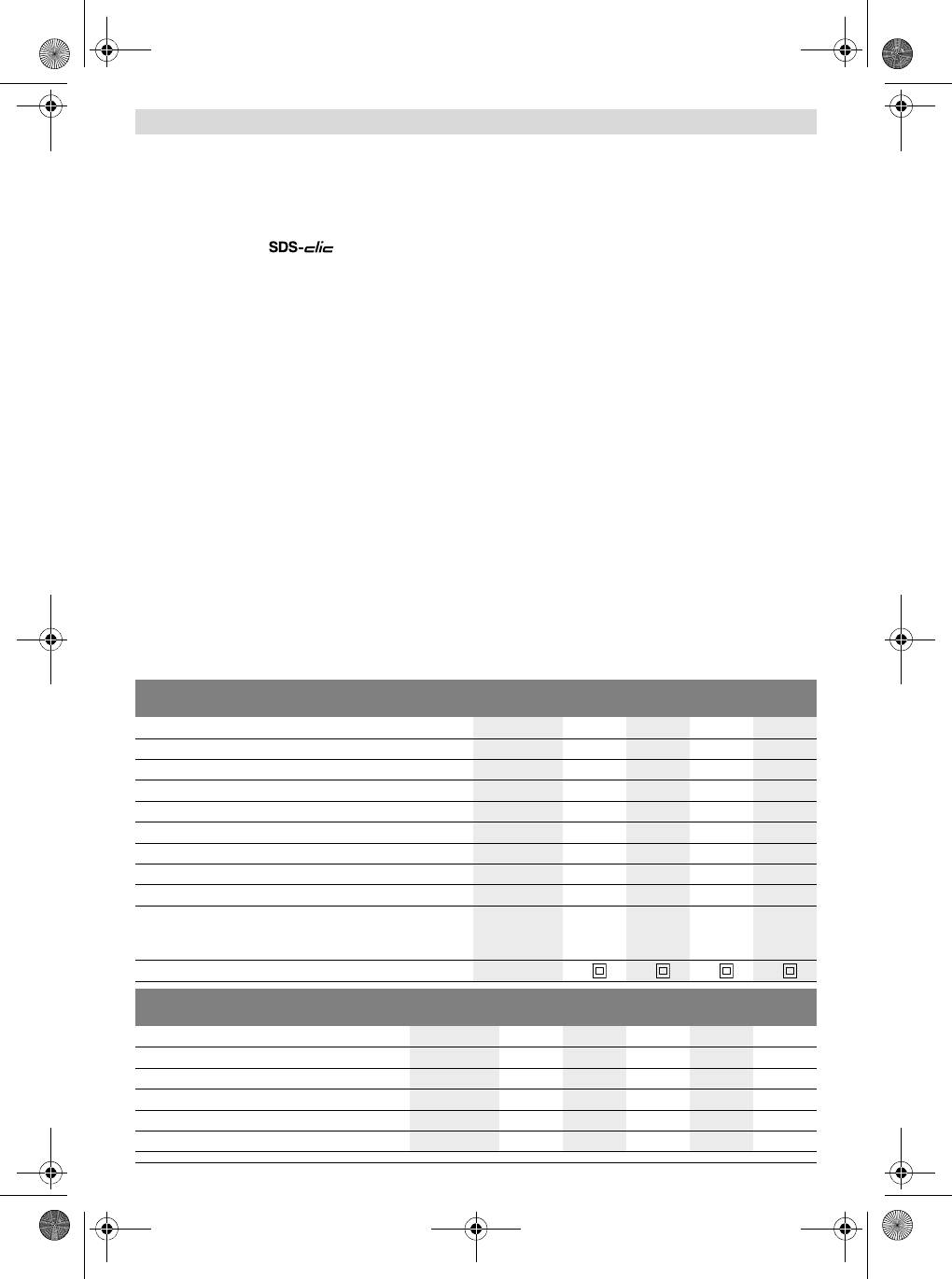
Technical Data
Angle Grinder GWS ... 22-180
22-180
22-230
22-230
H
JH
H
JH
Article number
3 601 ... H81 L.. H81 M.. H82 L.. H82 M..
Rated power input
W22002200 2200 2200
Output power
W15001500 1500 1500
-1
Rated speed
min
8500 8500 6500 6500
Grinding disc diameter, max.
mm 180 180 230 230
Thread of grinder spindle
M 14 M 14 M 14 M 14
Thread length (max.) of grinder spindle
mm 25 25 25 25
Restarting Protection
– –
Reduced starting current
– –
Weight according to EPTA-Procedure 01/2003
– with vibration-damping auxiliary handle
kg
5.1
5.1
5.3
5.3
– with standard-auxiliary handle
kg
5.0
5.0
5.2
5.2
Protection class /II /II /II /II
Angle Grinder GWS ... 24-180
24-230
24-230
26-180
26-230
JH
H
JH
JH
JH
Article number 3 601 ... H83 M.. H84 L.. H84 M.. H55 M.. H56 M..
Rated power input
W24002400 2400 2600 2600
Output power
W16001600 1600 1700 1700
Rated speed
min
-1
8500 6500 6500 8500 6500
Grinding disc diameter, max.
mm 180 230 230 180 230
Thread of grinder spindle
M 14 M 14 M 14 M 14 M 14
Bosch Power Tools 1 609 92A 0B8 | (5.8.13)
OBJ_BUCH-777-009.book Page 20 Monday, August 5, 2013 11:15 AM
20 | English
Angle Grinder GWS ... 24-180
24-230
24-230
26-180
26-230
JH
H
JH
JH
JH
Thread length (max.) of grinder spindle
mm 25 25 25 25 25
Restarting Protection
–
Reduced starting current
–
Weight according to EPTA-Procedure 01/2003
– with vibration-damping auxiliary handle
kg
5.1
5.2
5.3
6.0
6.1
– with standard-auxiliary handle
kg
5.0
5.1
5.2
5.9
6.0
Protection class /II /II /II /II /II
The values given are valid for a nominal voltage [U] of 230 V. For different voltages and models for specific countries, these values can vary.
Only for power tools without reduced starting current: Starting cycles generate brief voltage drops. Interference with other equipment/machines may
occur in case of unfavourable mains system conditions. Malfunctions are not to be expected for system impedances below 0.25 ohm.
Declaration of Conformity
Provide for sufficient dust extraction when cutting
stone.
We declare under our sole responsibility that the product de-
scribed under “Technical Data” is in conformity with the fol-
The protection guard for cutting 13 is mounted in the same
lowing standards or standardization documents: EN 60745
manner as the protection guard for grinding 5.
according to the provisions of the directives 2011/65/EU,
Cutting Guide with Dust Extraction Protection Guard
2004/108/EC, 2006/42/EC.
The cutting guide with dust extraction protection guard 24 is
Technical file (2006/42/EC) at:
mounted in the same manner as the protection guard for
Robert Bosch GmbH, PT/ETM9,
grinding 5.
D-70745 Leinfelden-Echterdingen
Auxiliary Handle
Henk Becker
Helmut Heinzelmann
Operate your machine only with the auxiliary handle 3.
Executive Vice President
Head of Product Certification
Engineering
PT/ETM9
Screw the auxiliary handle 3 on the right or left of the machine
head depending on the working method.
Hand Guard
For operations with the rubber sanding plate 20 or with
the cup brush/wheel brush/flap disc, always mount the
Robert Bosch GmbH, Power Tools Division
D-70745 Leinfelden-Echterdingen
hand guard 18.
21.06.2013
The hand guard 18 is fastened with the auxiliary handle 3.
Mounting the Grinding Tools
Assembly
Before any work on the machine itself, pull the mains
Mounting the Protective Devices
plug.
Before any work on the machine itself, pull the mains
Do not touch grinding and cutting discs before they
plug.
have cooled down. The discs can become very hot while
working.
Note: After breakage of the grinding disc during operation or
damage to the holding fixtures on the protection guard/power
Clean the grinder spindle 4 and all parts to be mounted.
tool, the machine must promptly be sent to an after-sales ser-
For clamping and loosening the grinding tools, lock the grind-
vice agent for maintenance for addresses, see section “After-
er spindle with the spindle lock button 1.
sales Service and Application Service”.
Actuate the spindle lock button only when the grinder
Protection Guard for Grinding
spindle is at a standstill. Otherwise, the machine may be-
come damaged.
Place the protection guard 5 on the spindle collar. Adjust the
position of the protection guard 5 to the requirements of the
Grinding/Cutting Disc
operation and lock the protection guard 5 with the locking
Pay attention to the dimensions of the grinding tools. The
screw 6.
mounting hole diameter must fit the mounting flange without
Adjust the protection guard 5 in such a manner that
play. Do not use reducers or adapters.
sparking is prevented in the direction of the operator.
When using diamond cutting discs, pay attention that the di-
Protection Guard for Cutting
rection-of-rotation arrow on the diamond cutting disc and the
direction of rotation of the machine (see direction-of-rotation
For cutting with bonded abrasives, always use the pro-
arrow on the machine head) agree.
tection guard for cutting 13.
See graphics page for the mounting sequence.
1 609 92A 0B8 | (5.8.13) Bosch Power Tools
English | 21
To fasten the grinding/cutting disc, screw on the clamping nut
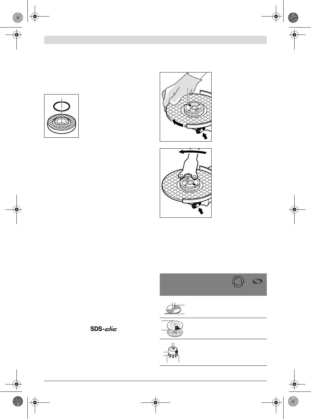
Use only a flawless, undamaged quick-clamping nut 11.
9 and tighten with the two-pin spanner; see Section “Quick-
When screwing on, pay attention that the side of the
clamping Nut ”.
quick-clamping nut 11 with printing does not face the
After mounting the grinding tool and before switching
grinding disc; the arrow must point to the index mark 27.
on, check that the grinding tool is correctly mounted
Lock the grinder spindle with
and that it can turn freely. Make sure that the grinding
the spindle lock button 1. To
tool does not graze against the protection guard or oth-
tighten the quick-clamping
er parts.
nut, firmly turn the grinding
A plastic part (O-ring) is fitted around
disc in clockwise direction.
the centring collar of mounting flange 7.
If the O-ring is missing or damaged,
the mounting flange 7 must be replaced
before resuming operation.
Flap Disc
For operations with the flap disc, always mount the
A properly attached, undam-
hand guard 18.
aged quick-clamping nut can
be loosened by hand when
Rubber Sanding Plate
turning the knurled ring in an-
For operations with the rubber sanding plate 20, al-
ticlockwise direction.
ways mount the hand guard 18.
Never loosen a tight quick-
See graphics page for the mounting sequence.
clamping nut with pliers.
Before mounting the rubber sanding plate 20, put the 2 spac-
Always use the two-pin
er discs 19 onto the grinder spindle 4.
spanner. Insert the two-pin
spanner as shown in the illus-
Screw on the round nut 22 and tighten with the two-pin span-
tration.
ner.
Cup Brush/Disc Brush
For operations with the cup brush/wheel brush, always
Approved Grinding Tools
mount the hand guard 18.
See graphics page for the mounting sequence.
All grinding tools mentioned in these operating instructions
can be used.
The cup brush/disc brush must be able to be screwed onto
-1
the grinder spindle until it rests firmly against the grinder
The permissible speed [min
] or the circumferential speed
spindle flange at the end of the grinder spindle threads. Tight-
[m/s] of the grinding tools used must at least match the values
en the cup brush/disc brush with an open-end spanner.
given in the table.
Therefore, observe the permissible rotational/circumferen-
Grinding Cup
tial speed on the label of the grinding tool.
When working with the grinding cup, mount the special
protection guard 15.
max.
The grinding cup 16 should never project further out of the
[mm]
[mm]
protection guard 15 than necessary for the respective grind-
D b d [min
-1
] [m/s]
ing application. Adjust the protection guard 15 accordingly to
this dimension.
180
8
22.2
8500
80
See graphics page for the mounting sequence.
230
8
22.2
6500
80
Screw on clamping nut 9 and tighten with two-pin spanner
17.
180
8500
80
Quick-clamping Nut
––
230
6500
80
For convenient changing of grinding tools without the use of
additional tools, you can use the quick-clamping nut 11 in-
stead of the clamping nut 9.
The quick-clamping nut 11 may be used only for grind-
100 30 M 14 8500 45
ing or cutting discs.
Bosch Power Tools 1 609 92A 0B8 | (5.8.13)
27
OBJ_BUCH-777-009.book Page 21 Monday, August 5, 2013 11:15 AM
d
D
b
D
d
b
D
OBJ_BUCH-777-009.book Page 22 Monday, August 5, 2013 11:15 AM
22 | English
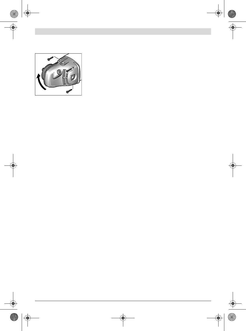
Rotating the Machine Head
Switching On and Off
Before any work on the machine itself, pull the mains
To start the power tool, press the On/Off switch 2 forward
plug.
and then down.
The machine head can be
To lock-on the pressed On/Off switch 2, push the On/Off
rotated with respect to
switch 2 further forward.
the machine housing in
To switch off the power tool, release the On/Off switch 2, or
90° steps. In this man-
when it is locked, briefly press the On/Off switch 2 and then
ner, the On/Off switch
release it.
can be brought into a
To save energy, only switch the power tool on when using it.
more convenient position
Switch Version without Lock-on (country-specific):
for special working situa-
tions, e. g., for cutting op-
To start the power tool, press the On/Off switch 2 forward
erations using the cutting
and then down.
guide with dust extrac-
To switch off the machine, release the On/Off switch 2.
tion protection guard 24 or for left-handed persons.
Check grinding tools before using. The grinding tool
Completely unscrew the four screws. Rotate the machine
must be mounted properly and be able to move freely.
head carefully, without removing it from the housing, to the
Carry out a test run for at least one minute with no load.
new position. Screw in and tighten the four screws again.
Do not use damaged, out-of-centre or vibrating grind-
ing tools. Damaged grinding tools can burst and cause in-
Dust/Chip Extraction
juries.
Dusts from materials such as lead-containing coatings,
Restarting Protection (GWS 22-180 JH/
some wood types, minerals and metal can be harmful to
GWS22-230JH/GWS24-180JH/GWS24-230JH/
one’s health. Touching or breathing-in the dusts can cause
GWS 26-180 JH/GWS 26-230 JH)
allergic reactions and/or lead to respiratory infections of
The restarting protection feature prevents uncontrolled re-
the user or bystanders.
starting of the machine after an interruption in the power sup-
Certain dusts, such as oak or beech dust, are considered
ply.
as carcinogenic, especially in connection with wood-treat-
ment additives (chromate, wood preservative). Materials
To restart the operation, switch the On/Off switch 2 to the
containing asbestos may only be worked by specialists.
Off position and start the machine again.
– As far as possible, use a dust extraction system suita-
Reduced starting current (GWS 22-180 JH/
ble for the material.
GWS22-230JH/GWS24-180JH/GWS24-230JH/
– Provide for good ventilation of the working place.
GWS 26-180 JH/GWS 26-230 JH)
– It is recommended to wear a P2 filter-class respirator.
The electronic reduced starting current limits the power con-
Observe the relevant regulations in your country for the
sumption when switching the tool on and enables operation
materials to be worked.
from a 13 ampere fuse.
Prevent dust accumulation at the workplace. Dusts can
Note: When the machine runs at full speed immediately after
easily ignite.
switching on, the reduced starting current and the restarting
protection have failed. The power tool should be sent imme-
Operation
diately to an after-sales service (for addresses, see section
“After-sales Service and Application Service”.
Starting Operation
Working Advice
Observe correct mains voltage! The voltage of the pow-
Exercise caution when cutting slots in structural walls;
er source must agree with the voltage specified on the
see Section “Information on Structures”.
nameplate of the machine. Power tools marked with
230 V can also be operated with 220 V.
Clamp the workpiece if it does not remain stationary
due to its own weight.
When operating the machine with power from mobile genera-
tors that do not have sufficient reserve capacity or are not
Do not strain the machine so heavily that it comes to a
equipped with suitable voltage control with starting current
standstill.
amplification, loss of performance or untypical behavior can
After heavily straining the power tool, continue to run
occur upon switching on.
it at no-load for several minutes to cool down the acces-
Please observe the suitability of the power generator being
sory.
used, particularly with regard to the mains voltage and fre-
Do not touch grinding and cutting discs before they
quency.
have cooled down. The discs can become very hot while
working.
Do not use the power tool with a cut-off stand.
1 609 92A 0B8 | (5.8.13) Bosch Power Tools
OBJ_BUCH-777-009.book Page 23 Monday, August 5, 2013 11:15 AM
English | 23
Note: When not using for extended periods, pull the mains
Switch on the machine
plug out of the socket outlet. When the mains plug is inserted
and place the front part
and mains voltage is given, the power tool, even when
of the cutting guide on
switched off, still consumes a low amount of current.
the workpiece. Slide the
machine with moderate
Rough Grinding
feed, adapted to the ma-
Never use a cutting disc for roughing.
terial to be worked.
The best roughing results are achieved when setting the ma-
chine at an angle of 30° to 40°. Move the machine back and
forth with moderate pressure. In this manner, the workpiece
will not become too hot, does not discolour and no grooves
are formed.
Flap Disc
With the flap disc (accessory), curved surfaces and profiles
For cutting expecially hard material, e. g., concrete with high
can be worked.
pebble content, the diamond cutting disc can overheat and
become damaged as a result. This is clearly indicated by cir-
Flap discs have a considerably higher service life, lower noise
cular sparking, rotating with the diamond cutting disc.
levels and lower sanding temperatures than conventional
In this case, interrupt the cutting process and allow the dia-
sanding sheets.
mond cutting disc to cool by running the machine for a short
Cutting Metal
time at maximum speed with no load.
For cutting with bonded abrasives, always use the pro-
Noticeable decreasing work progress and circular sparking
tection guard for cutting 13.
are indications of a diamond cutting disc that has become
When cutting, work with moderate feed, adapted to the mate-
dull. Briefly cutting into abrasive material (e. g. lime-sand
rial being cut. Do not exert pressure onto the cutting disc, tilt
brick) can resharpen the disc again.
or oscillate the machine.
Information on Structures
Do not reduce the speed of running down cutting discs by ap-
Slots in structural walls are subject to the Standard DIN 1053
plying sideward pressure.
Part 1, or country-specific regulations.
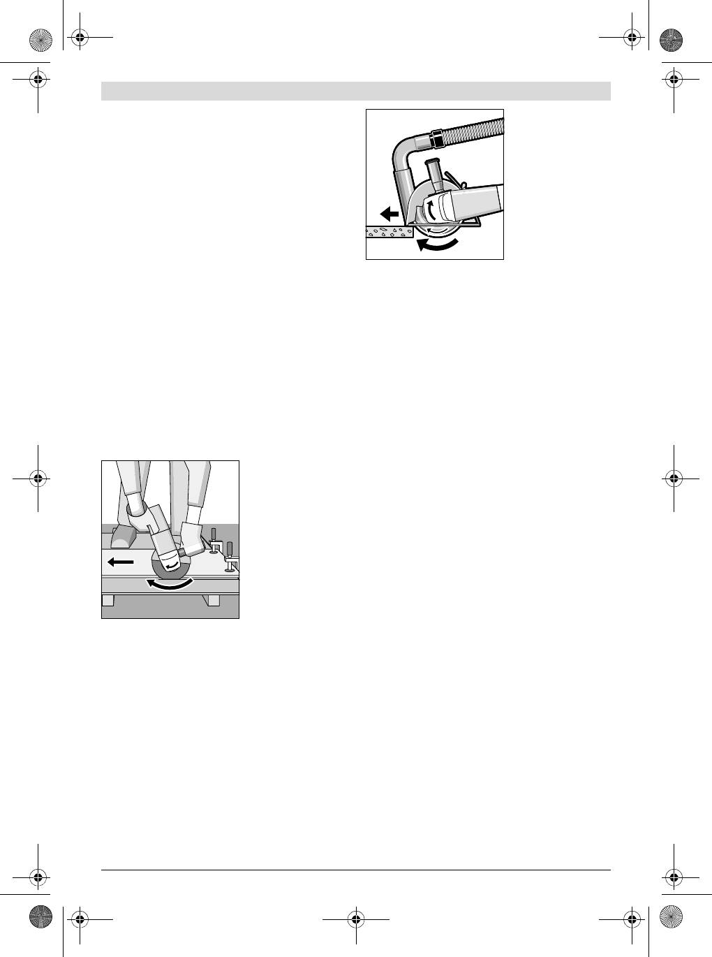
The machine must al-
These regulations are to be observed under all circumstanc-
ways work in an up-
es. Before beginning work, consult the responsible structural
grinding motion. Other-
engineer, architect or the construction supervisor.
wise, the danger exists
of it being pushed un-
Maintenance and Service
controlled out of the
cut.
Maintenance and Cleaning
Before any work on the machine itself, pull the mains
plug.
For safe and proper working, always keep the machine
and ventilation slots clean.
In extreme conditions, always use dust extraction as
far as possible. Blow out ventilation slots frequently
When cutting profiles and square bar, it is best to start at the
and install a residual current device (RCD). When work-
smallest cross section.
ing metals, conductive dust can settle in the interior of the
Cutting Stone
power tool. The total insulation of the power tool can be im-
Provide for sufficient dust extraction when cutting
paired.
stone.
Please store and handle the accessory(-ies) carefully.
Wear a dust respirator.
If the replacement of the supply cord is necessary, this has to
The machine may be used only for dry cutting/grinding.
be done by Bosch or an authorized Bosch service agent in or-
der to avoid a safety hazard.
For cutting stone, it is best to use a diamond cutting disc.
When using the cutting guide with dust extraction protection
After-sales Service and Application Service
guard 24, the vacuum cleaner must be approved for vacuum-
Our after-sales service responds to your questions concern-
ing masonry dust. Suitable vacuum cleaners are available
ing maintenance and repair of your product as well as spare
from Bosch.
parts. Exploded views and information on spare parts can al-
so be found under:
www.bosch-pt.com
Bosch’s application service team will gladly answer questions
concerning our products and their accessories.
Bosch Power Tools 1 609 92A 0B8 | (5.8.13)
