Sony SDM-S205FB: инструкция
Раздел: Компьютерная техника, комплектующие, аксессуары
Тип: Монитор
Инструкция к Монитору Sony SDM-S205FB
2-649-019-
04
(1)
© 2005 Sony Corporation
SDM-S205
取扱説明書
お買い上げいただきありがとうございます。
電気製品は安全のための注意事項を守らないと、
火災や人身事故になることがあります。
この取扱説明書には、事故を防ぐための重要な注意事項と製品
の取り扱いかたを示しています。
この取扱説明書と別冊の「安全
のために」をよくお読みのうえ
、製品を安全にお使いください。
お読みになったあとは、いつでも見られるところに必ず保管し
てください。
2
(for the black model)
(for the silver model)
この装置は、情報処理装置等電波障害自主規制協議会(
VCCI
)
の基準に基づくクラス
B
情報技術装置です。この装置は、家
庭環境で使用することを目的としていますが、この装置がラジ
オやテレビジョン受信機に近接して使用されると、受信障害を
引き起こすことがあります。
取扱説明書に従って正しい取り扱いをしてください。
当社は国際エネルギースタープロ
グラムの参加事業者として、本製
品が国際エネルギースタープログ
ラムの基準に適合していると判断
します。
本製品は社団法人電子情報技術産業協会が定めた「表示装置の
静電気および低周波電磁界」に関するガイドラインに適合して
おります。
This monitor complies with
the TCO’99 guidelines.
This monitor complies with
the TCO’03 guidelines.
3
目次
• Macintosh
は、
Apple Computer,
Inc.
の米国およびその他の国にお
ける登録商標です。
• Windows
®
は、米国
Microsoft
Corporation
の米国およびその他
の国における登録商標です。
• IBM PC/AT
と
VGA
は、
IBM
Corporation
の登録商標です。
• VESA
と
DDC
™
は、
Video
Electronics Standards
Association
の商標です。
•
E
NERGY
S
TAR
®
マークは、米国
環境保護局の商標です。
• Adobe
、
Acrobat
は
Adobe
Systems Incorporated
(アドビ
システムズ社)の商標です。
•
この取扱説明書に表記されている
上記以外の製品名は、それぞれの
会社の商標または登録商標です。
•
この取扱説明書では、「
®
」と「
™
」
については一部表記を省略してい
ます。
http://www.sony.co.jp/
使用上のご注意
. . . . . . . . . . . . . . . . . . . . . . . . . . . . . . . . . . 4
ディスプレイの型名を確認する
. . . . . . . . . . . . . . . . . . . . . . . 5
各部の名前とはたらき
. . . . . . . . . . . . . . . . . . . . . . . . . . . . . . 5
接続と設定
. . . . . . . . . . . . . . . . . . . . . . . . . . . . . . . . . . . . . .6
準備
1
:スタンドを組み立てる
. . . . . . . . . . . . . . . . . . . . . . . 6
準備
2
:ビデオ信号ケーブルをつなぐ
. . . . . . . . . . . . . . . . . . . 7
準備
3
:
USB
マウスや
USB
キーボードなどをつなぐ
(
USB
端子があるモデルのみ)
. . . . . . . . . . . . . . . . . . 8
準備
4
:オーディオ接続コードをつなぐ
. . . . . . . . . . . . . . . . . 9
準備
5
:電源コードをつなぐ
. . . . . . . . . . . . . . . . . . . . . . . . . 9
準備
6
:コード類をまとめて端子カバーを閉める
. . . . . . . . . . . 9
準備
7
:電源を入れる
. . . . . . . . . . . . . . . . . . . . . . . . . . . . . 10
準備
8
:ディスプレイの向きと高さを変える
. . . . . . . . . . . . . 11
画面を縦
/
横に切り換えて使う
(ピボットスタンド付きモデルのみ)
. . . . . . . . . . . . . . . . . . . 12
入力を切り換えるには
(
INPUT1/INPUT2
)
. . . . . . . . . . . . . 12
調整する
. . . . . . . . . . . . . . . . . . . . . . . . . . . . . . . . . . . . . .13
メニュー操作のしかた
. . . . . . . . . . . . . . . . . . . . . . . . . . . . . 13
メニュー一覧
. . . . . . . . . . . . . . . . . . . . . . . . . . . . . . . . . . . 14
画質調整メニュー
. . . . . . . . . . . . . . . . . . . . . . . . . . . . . 15
画調整メニュー(アナログ
RGB
信号のみ)
. . . . . . . . . . . 15
ズームメニュー
. . . . . . . . . . . . . . . . . . . . . . . . . . . . . . 16
メニュー位置メニュー
. . . . . . . . . . . . . . . . . . . . . . . . . . 16
自動入力センサーメニュー
. . . . . . . . . . . . . . . . . . . . . . . 16
LANGUAGE
メニュー
. . . . . . . . . . . . . . . . . . . . . . . . . 17
0
リセットメニュー(お買い上げ時の設定に戻す)
. . . . . . . . 17
メニューロック
. . . . . . . . . . . . . . . . . . . . . . . . . . . . . . 17
オプションメニュー
. . . . . . . . . . . . . . . . . . . . . . . . . . . 17
機能
. . . . . . . . . . . . . . . . . . . . . . . . . . . . . . . . . . . . . . . . .17
省電力機能(パワーセーブ機能)
. . . . . . . . . . . . . . . . . . . . . 17
節電しながら使う(
ECO
モード)
. . . . . . . . . . . . . . . . . . . . 17
自動輝度調整機能(ライトセンサー)
. . . . . . . . . . . . . . . . . . 18
自動画質調整機能(アナログ
RGB
信号のみ)
. . . . . . . . . . . . 18
KVM
機能(
Keyboard-Video-Mouse
機能)
. . . . . . . . . . . . 18
故障かな?と思ったら
. . . . . . . . . . . . . . . . . . . . . . . . . . . . .19
表示メッセージについて
. . . . . . . . . . . . . . . . . . . . . . . . . . . 19
本機の症状と対処のしかた
. . . . . . . . . . . . . . . . . . . . . . . . . 20
保証書とアフターサービス
. . . . . . . . . . . . . . . . . . . . . . . . . .22
保証書
. . . . . . . . . . . . . . . . . . . . . . . . . . . . . . . . . . . . . . . 22
アフターサービスについて
. . . . . . . . . . . . . . . . . . . . . . . . . 22
主な仕様
. . . . . . . . . . . . . . . . . . . . . . . . . . . . . . . . . . . . . .23
TCO’99 Eco-document (for the black model) . . . . . . . . . . . i
TCO’03 Eco-document (for the silver model) . . . . . . . . . . .ii
4
使用上のご注意
電源について
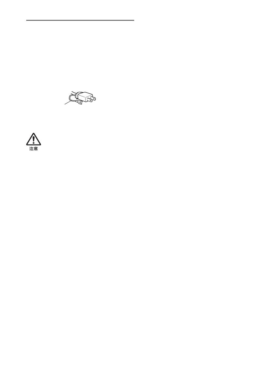
付属の電源コードをお使いください。別売りの電源コード
をお使いになる場合は、下図のプラグ形状例を参考にして
ください。
安全のため、電源コードにはアース線がついています。電
源コンセントにプラグを差し込む前に、必ずアース接続を
行ってください。電源コードを抜くときは、先にプラグを
抜いてからアース線をはずしてください。
アースキャップおよびケーブルキャップは幼児の手
の届かないところへ保管する
お子様が誤って飲むと、窒息死するおそれがあ
ります。
万一誤って飲み込まれた場合は、ただちに医師
に相談してください。
特に小さいお子様にはご注意ください。
使用・設置場所について
次のような場所での使用・設置はおやめください。
•
異常に高温になる場所
炎天下や夏場の窓を閉め切った自動車内はとくに高温に
なり、放置すると変形したり、故障したりすることがあ
ります。
•
直射日光のあたる場所、熱器具の近くなど、温度の高い
場所
変形したり、故障したりすることがあります。
•
振動の多い場所
•
強力な磁気のある場所
•
砂地、砂浜などの砂ぼこりの多い場所
海辺や砂地、あるいは砂ぼこりが起こる場所などでは、
砂がかからないようにしてください。故障の原因になる
ばかりか、修理できなくなることがあります。
背面上部の通風孔は熱くなりますので触らないようにご
注意ください。
液晶画面について
•
液晶画面を太陽に向けたままにすると、液晶画面を傷め
てしまいます。窓際や室外に置くときなどはご注意くだ
さい。
•
液晶画面を強く押したり、ひっかいたり、上にものを置
いたりしないでください。画面にムラが出たり、液晶パ
ネルの故障の原因になります。
•
寒いところでご使用になると、画像が尾を引いて見えた
り、画面が暗く見えたりすることがありますが、故障で
はありません。温度が上がると元に戻ります。
•
静止画を継続的に表示した場合、残像を生じることがあ
りますが、時間の経過とともに元に戻ります。
•
使用中に画面やキャビネットがあたたかくなることがあ
りますが、故障ではありません。
液晶ディスプレイパネルについて
本機の液晶ディスプレイパネルは非常に精密度の高い技
術でつくられていますが、黒い点が現れたり、赤と青、緑
の点が消えないことがあります。また、見る角度によって
すじ状の色むらや明るさのムラが見える場合があります。
これらは、液晶ディスプレイの構造によるもので、故障で
はありません。
これらの点をご了承のうえ、本機をお使いください。
お手入れについて
•
お手入れをする前に、必ず電源プラグをコンセントから
抜いてください。
•
液晶の画面は特殊加工がされていますので、なるべく画
面に触れないようにしてください。また画面の汚れをふ
きとるときは、乾いた柔らかい布でふきとってください。
•
アルコール、シンナー、ベンジンなどは使わないでくだ
さい。変質したり、塗装がはげたりすることがあります。
•
化学ぞうきんをご使用の際は、その注意書きに従ってく
ださい。
•
殺虫剤のような揮発性のものをかけたり、ゴムやビニー
ル製品に長時間接触させると、変質したり、塗装がはげ
たりすることがあります。
搬送するときは
•
本機を運ぶときは、本機に接続されているケーブル等を
すべてはずし、高さ調整スタンドをお使いの際は、液晶
ディスプレイを一番上まで上げてから、画面を傷つけな
いよう注意し、液晶ディスプレイの両側をしっかりと
持ってください。落としたりするとけがや故障の原因と
なることがあります。
•
修理や引っ越しなどで本機を運ぶ場合は、お買い上げ時
に本機が入っていた箱と、クッション材を使ってくださ
い。高さ調整スタンドをお使いの際は、ストッパーピンで
液晶ディスプレイを固定してください。
廃棄するときは
•
一般の廃棄物と一緒にしないでください。
ごみ廃棄場で処分されるごみの中にディスプレイを捨て
ないでください。
•
本機の蛍光管の中には水銀が含まれています。廃棄の際
は、地方自治体の条例または規則に従ってください。
AC100 V
用
アース線
プラグ形状例
5
ディスプレイの型名を確認する
はじめに、ディスプレイの型名を確認してください。
型名は、ディスプレイの後面の
ID
ラベルに記されていま
す(例:
SDM-S205F
のように記載されています)。
お使いのディスプレイによって、機能やメニューの一部が
使用できないことがありますのでご注意ください。
各部の名前とはたらき
使いかたについての詳しい説明は( )内のページをご覧
ください。
イラストは一例です。
お使いのディスプレイとは異なることがあります。
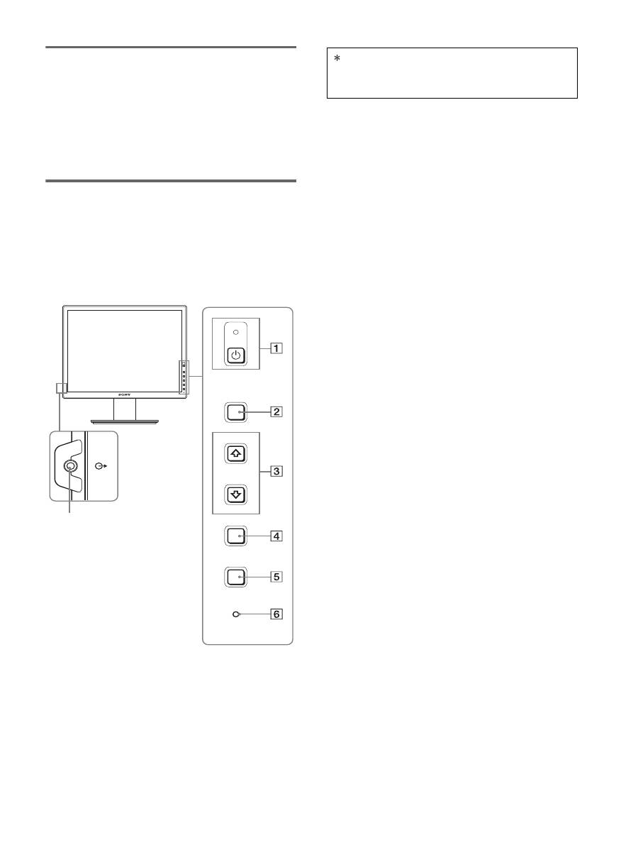
ディスプレイ前面
A
1
(電源)スイッチと
1
(電源)ランプ
(
10
、
17
ページ)
1
(電源)ランプが赤色に点灯しているときに押すと、
ディスプレイの電源が入ります。もう一度押すと、ディ
スプレイの電源が切れます。
1
(電源)ランプが消灯しているときは、
8
の
MAIN
POWER
(主電源)スイッチで主電源を入れてくださ
い。
B
MENU
(メニュー)ボタン(
13
ページ)
メニュー画面を出すときや、消すときに押します。
C
m
/
M
ボタン(
13
ページ)
メニュー画面でメニューや項目を選んだり、調整した
りするときに使います。
D
OK
ボタン(
13
ページ)
3
の
m
/
M
ボタンで選んだメニューや項目、調整値を決
定するときに押します。
INPUT
(
12
ページ)
また、メニュー画面が表示されていないときに押すと、
本 機 に 入 力 さ れ る 信 号 を 切 り 換 え て、見 た い コ ン
ピュータを選ぶことができます。
E
ECO
ボタン
(
17
ページ)
節電するときに押します。
また、メニュー画面が表示されていないとき、このボ
タンを
3
秒以上押し続けると画質を自動的に調整する
ことができます(ワンタッチオートアジャスト機能)。
(ただしアナログ
RGB
信号のみ)
F
ライトセンサー(
18
ページ)
周囲の明るさを検知するためのセンサーです。セン
サーをおおわないようにしてください。
G
音声出力端子(
9
ページ)
スピーカーや他のオーディオ機器へ音声を出力すると
きに使います。
MENU
INPUT
ECO
OK
7
マークが付いている内容は、モデルにより異なりま
す。詳しくは「主な仕様」(23 ページ)でご確認くだ
さい。
6
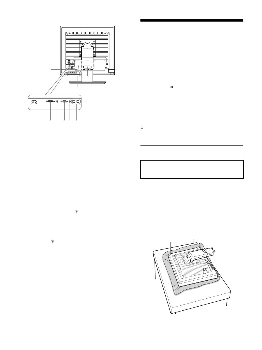
ディスプレイ後面
H
MAIN POWER
(主電源)スイッチ(
10
ページ)
ディスプレイの主電源を入
/
切します。
I
電源入力端子(
9
ページ)
電源コードをつなぎます。
J
DVI-D
入力端子(デジタル
RGB
)(
8
ページ)
DVI Rev. 1.0
準拠のデジタル
RGB
信号を入力します。
K
HD15
(
RGB
)入力端子(アナログ
RGB
)
(
8
ページ)
アナログ
RGB
の映像信号(
0.700 Vp-p
、正極性)と
同期信号を入力します。
L
コード留め(
9
ページ)
ケーブルやコード類をまとめます。
M
USB
ダウンストリーム端子(
USB
端子があるモ
デルのみ)(
8
ページ)
USB
マウスと
USB
キーボードを本機につなぐことに
より、
2
台までのコンピュータを本機で入力を切り換
えながら使うことができます。
N
USB
アップストリーム端子(
USB
端子があるモ
デルのみ)
USB
ケーブルをコンピュータと本機につなぎます。
O
盗難防止用ロック
キーケーブルロックなど、市販の盗難防止用ケーブル
をつなぐことができます。
盗難防止用ケーブルについての連絡先は、日本ポラデ
ジタル(株)営業部です。
P
INPUT1
用音声入力端子
INPUT1
に接続されたコンピュータ、または他のオー
ディオ機器の音声出力端子につないで、音声信号を入
力します。
Q
INPUT2
用音声入力端子
INPUT2
に接続されたコンピュータ、または他のオー
ディオ機器の音声出力端子につないで、音声信号を入
力します。
接続と設定
本機をお使いになる前に、下記のものがそろっていること
をご確認ください。
•
液晶ディスプレイ
•
電源コード
•
スタンドベース
• HD15-HD15
ビデオ信号ケーブル(アナログ
RGB
)
• DVI-D
ビデオ信号ケーブル(デジタル
RGB
)
•
オーディオ接続コード(ステレオミニプラグ)
• USB
ケーブル
• CD-ROM
(
Windows/Macintosh
ユーティリティ
/
取
扱説明書など)
•
保証書
•
クイックセットアップガイド
•
安全のために
•
ソニーご相談窓口のご案内
マークが付いている内容は、モデルにより異なります。
詳しくは「主な仕様」(
23
ページ)でご確認ください。
準備
1
:スタンドを組み立てる
x
付属のスタンドを使うとき
1
箱を開けてスタンドベースを取り出す。
2
部品を確認する。
•
スタンドベース(裏にネジがついています。)
3
机などの上に柔らかいマットなどを敷く。
直に本機を置くと、ディスプレイの液晶画面や本体を
傷つけるおそれがあります。
4
ディスプレイ本体を箱から取り出し、マットなどの上
にディスプレイの下端と机の端をそろえて置く。
qg
qs
qd
8
9
q; qh qaqj qf
本機を机などに置いたり、立てたりするときは、液晶画
面を強く押さないでください。画面の色むらや液晶パネ
ルの故障の原因になります。
ディスプレイ
スタンド
柔らかいマットなど
7
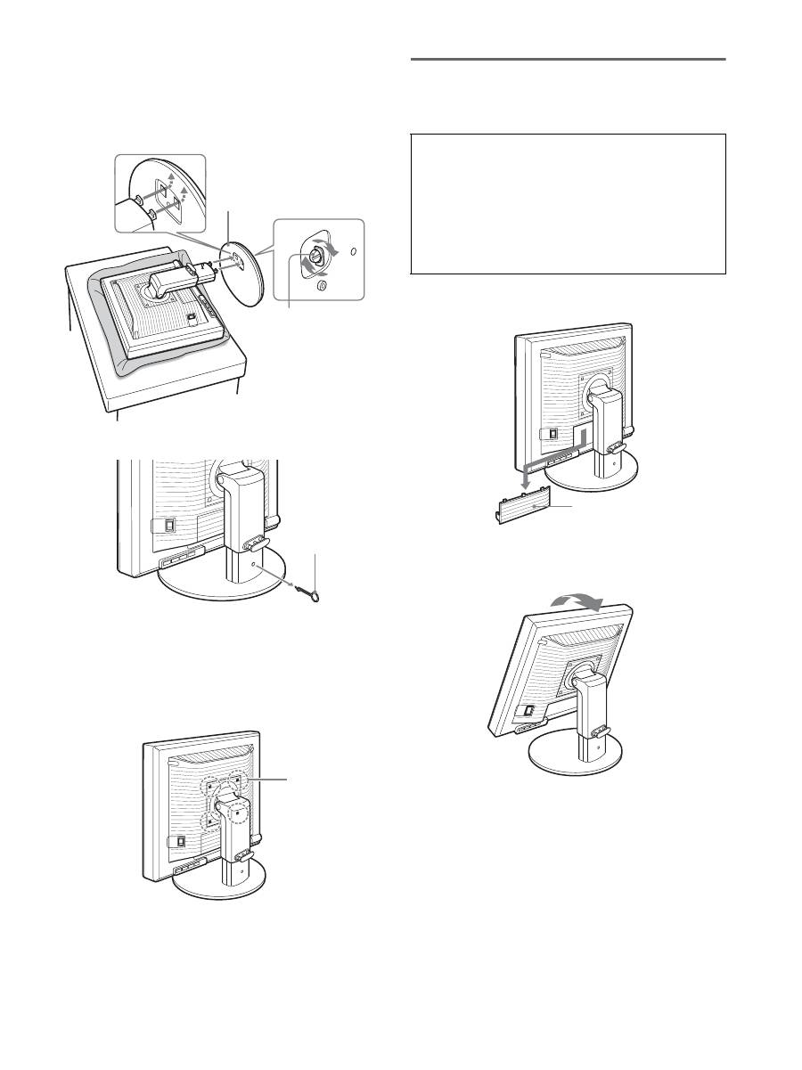
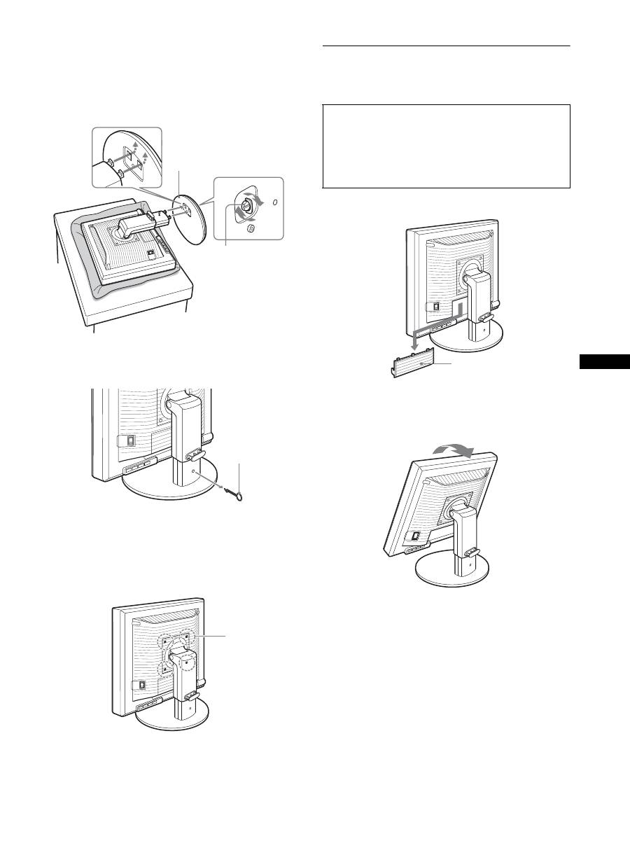
5
スタンドのツメをスタンドベースの穴に引っかけて、
スタンドベースを取り付ける。
1
スタンドベースの裏側にあるネジのハンドルを持ち上
げて、しっかり締める。
2
ネジがしっかり締まっていることを確かめて、ハンド
ルを倒す。
6
本機を立ててから、ストッパーピンを抜く。
ご注意
横にしたままストッパーピンを抜かないでください。
スタンドが勢いよく引き伸ばされ、本機が身体に当たったり落下
したりして、けがや故障の原因となることがあります。
x
VESA
スタンドを使うとき
ディスプレイ本体についているスタンドをはずすことに
より、市販の
VESA
スタンドを取り付けることができます。
準備
2
:ビデオ信号ケーブルを
つなぐ
1
端子カバーを引き下げる。
2
ディスプレイを上に傾ける。
さらにディスプレイの位置を上に移動させる。
1
スタンドベース
2
ネジ
ストッパー
ピン
VESA
対応
ネジ(
4
本)
本機とコンピュータの電源を切った状態でつないでく
ださい。
ご注意
•
ビデオ信号ケーブルのピンに、直接手を触れないでくださ
い。
•
ビデオ信号ケーブルのピンが曲がることを防ぐため端子の
向きをご確認ください。
端子カバー
8
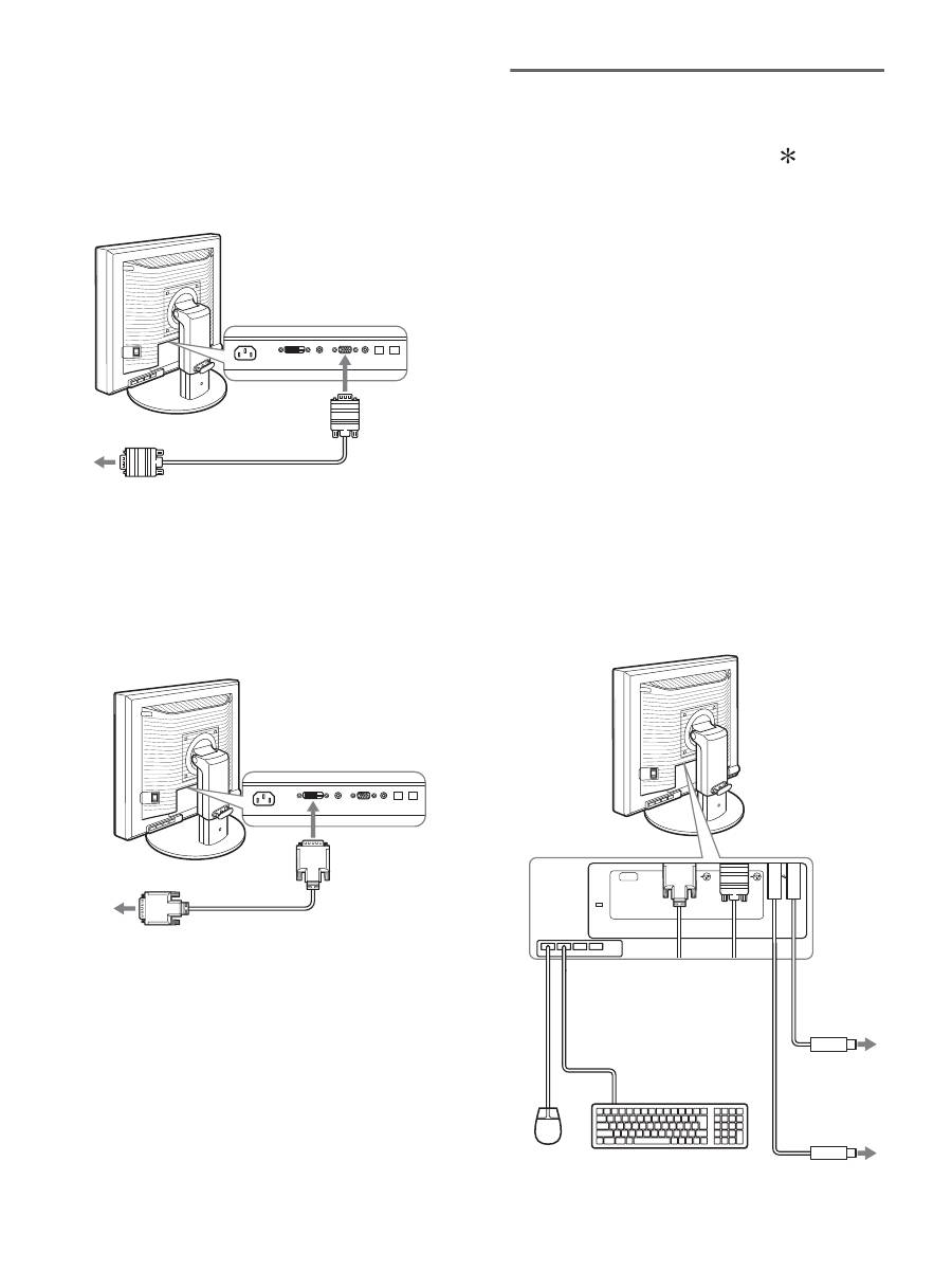
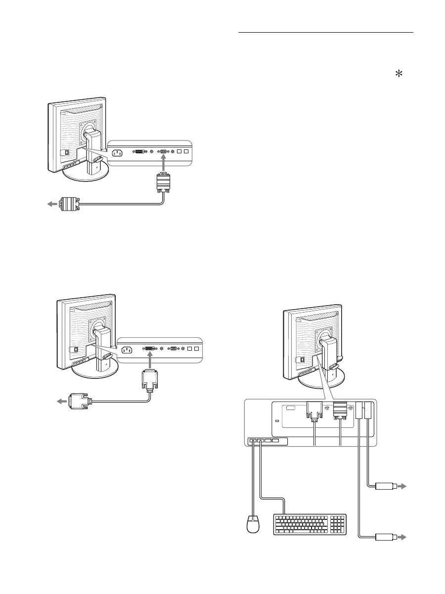
3
本機にビデオ信号ケーブルをつなぐ。
x
HD15
出力端子(アナログ
RGB
)のあるコン
ピュータをつなぐ
コンピュータを本機の
HD15
入力端子(アナログ
RGB
)
に、付属の
HD15-HD15
ビデオ入力信号ケーブル(ア
ナログ
RGB
)でつなぐ。
x
DVI
出力端子(デジタル
RGB
)のあるコン
ピュータをつなぐ
コンピュータを本機の
DVI-D
入力端子(デジタル
RGB
)に、付属の
DVI-D
ビデオ信号ケーブル(デジ
タル
RGB
)でつなぐ。
準備
3
:
USB
マウスや
USB
キーボードなどをつなぐ(
USB
端子があるモデルのみ)
USB
マウスや
USB
キーボードなどを本機につなぐことに
より、
2
台までのコンピュータを本機で入力を切り換えな
がら使うことができます(
KVM
機能)。
詳しくは、「
KVM
機能」(
18
ページ)をご覧ください。
USB
マウスや
USB
キーボードなどを本機で使わない場合
は、準備
4
へ進んでください。
1
付属の
USB
ケーブルで本機とコンピュータをつなぐ。
2
本機に
USB
マウスや
USB
キーボードなどをつなぐ。
Macintosh
をお使いのときは
USB
ダウンストリーム端子に、パワーボタンのある
Macintosh
用キーボードをつなぐと、キーボードのパ
ワーボタンが働きません。このときは、
Macintosh
本
体のパワーボタンで電源を入れるか、コンピュータに
直にキーボードをつないで電源を入れた後、
USB
ダウ
ンストリーム端子につないでください。
ご注意
•
本機の
USB
端子は
Windows2000 / Windows XP Professional
/ Windows XP Home edition / Macintosh
に対応しています。
•
すでにお使いのコンピュータに
USB
マウスや
USB
キーボード
などがつながっているときは、いったん取りはずしてください。
•
この方法で使用できるのは、コンピュータおよび
OS
が
USB
に対応しているときのみです。詳しくは、コンピュータまたは
OS
の取扱説明書をご覧ください。
コンピュータの
HD15
出力端子
(アナログ
RGB
)へ
HD15-HD15
ビデオ信号ケーブル
(アナログ
RGB
)(付属)
HD15
入力端子
(アナログ
RGB
)
へ
DVI-D
入力端子
(デジタル
RGB
)
コンピュータの
DVI
出力端子
(デジタル
RGB
)へ
DVI-D
ビデオ信号ケーブル(デジタル
RGB
)(付属)
AC IN
DVI-D
HD15
1
2
2
1
コンピュータの
USB
端子へ
USB
キーボード
USB
マウス
USB
ケーブル
(付属)
コンピュータの
USB
端子へ
USB
ケーブル(付属)
2
2
1
1
9
準備
4
:オーディオ接続コード
をつなぐ
音声を出力しないときは、この接続は不要です。
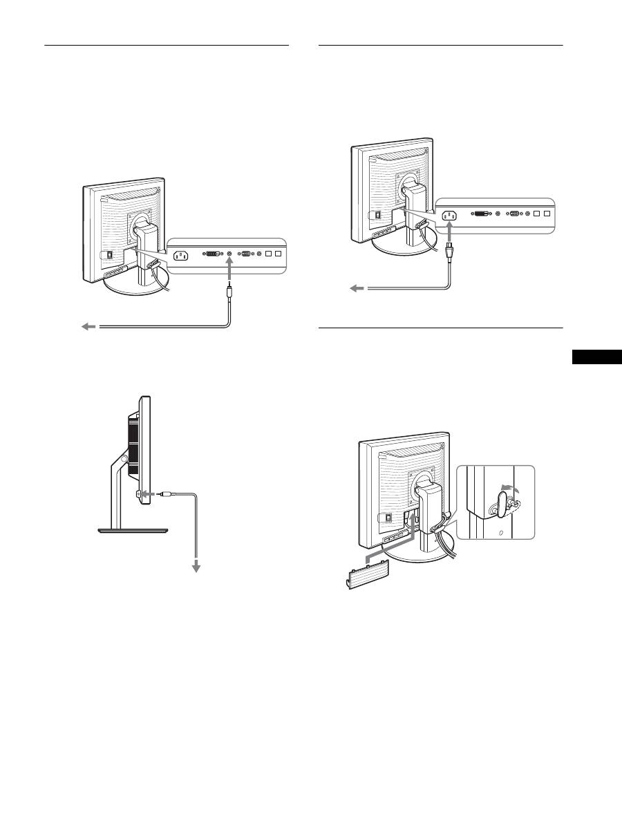
1
コンピュータまたはオーディオ機器と本機の音声入力
端子を、付属のオーディオ接続コードでつなぐ。
2
本機の音声出力端子に、オーディオジャックを突き当
たるまで差し込む。
本機の音声入力端子と音声出力端子の接続を完了するこ
とで、音声出力を切り換えることができます。
本機の音声入力端子には仕様で記された入力の範囲内で
オーディオ機器を接続してください。過大入力により故障
の原因となることがあります。
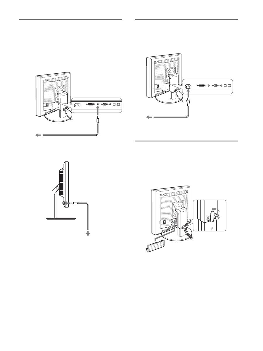
準備
5
:電源コードをつなぐ
1
本機に電源コードを突き当たるまで差し込む。
2
電源コンセントへ突き当たるまで差し込む。
準備
6
:コード類をまとめて端
子カバーを閉める
1
図のようにコードとケーブルをケーブルホルダーに通
す。
2
端子カバーを閉める。
ご注意
コード類は、長さに余裕を持たせて、たるむようにまとめてくだ
さい。ディスプレイの向きを変えたときに、コード類が引っ張ら
れると、はずれたり、断線の故障の原因となることがあります。
音声入力
端子へ
コンピュータまたはその他のオー
ディオ機器の音声出力端子へ
オーディオ接続コード(付属)
音声出力端子へ
オーディオ
ケーブル
(別売り)
電源入力端子へ
1
2
電源コンセントへ
電源コード(付属)
10
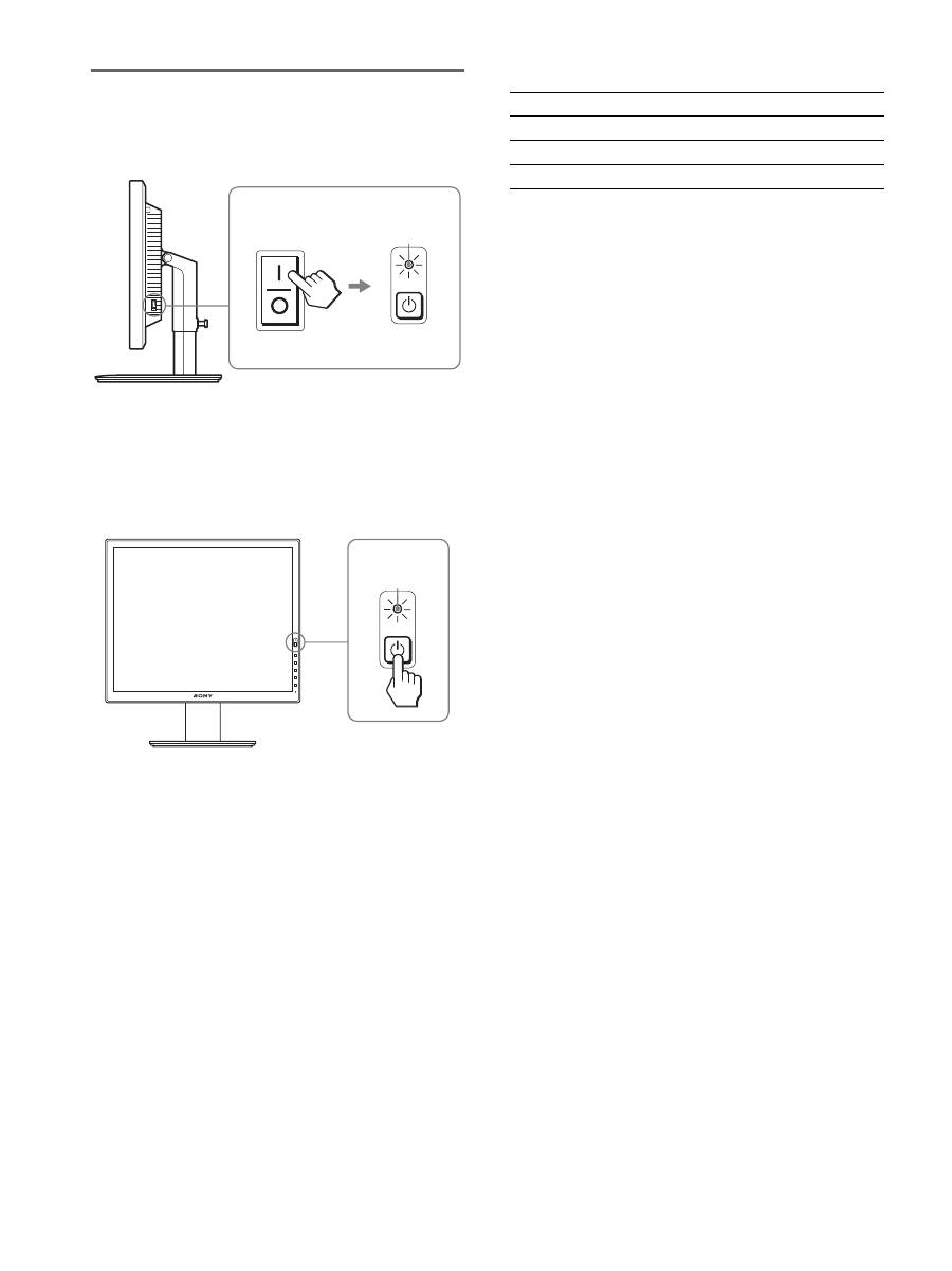
準備
7
:電源を入れる
1
1
(電源)ランプが赤色に点灯することを確認する。な
お、お買い上げ時の状態では、
[
側に設定されています。
ご注意
本機右側面の
MAIN POWER
(主電源)スイッチがお買い上げ時
に
[
側になっていない場合は、スイッチを
[
側に押して
1
(電源)
ランプが赤色に点灯することを確認してください。
2
本機正面右側の
1
(電源)スイッチを押す。
1
(電源)ランプが緑色に点灯します。
3
コンピュータの電源を入れる。
本機の電源を入れても画面に画像が出ないときは
•
ビデオ信号ケーブルや電源コードを正しくつないでいる
か確認する。
•
「
NO INPUT SIGNAL
」と表示されているとき
−コンピュータが省電力状態になっている。キーボードの
キーのどれかを押してみるか、マウスを動かしてみる。
−
OK
ボタンを押して、入力切り換えが正しいか確認す
る(
12
ページ)。
•
「
CABLE DISCONNECTED
」と表示されているとき
−ビデオ信号ケーブルを正しくつないでいるか確認する。
−
OK
ボタンを押して、入力切り換えが正しいか確認す
る(
12
ページ)。
•
「
OUT OF RANGE
」と表示されているとき
本機をつなぐ前につないでいたディスプレイがあるとき
は、そのディスプレイにつなぎ換えて、画像が出るか確
認する。
画像が出たら、コンピュータで以下の範囲に設定する。
詳しくは、「本機の症状と対処のしかた」(
20
ページ)を
ご覧ください。
モニタ用のドライバは不要です
本機はプラグ
&
プレイ機能(
DDC
)を搭載しており、
Windows
のプラグ
&
プレイ機能によりモニタの情報が自動的に認識されま
す。このため、モニタ用の特別なドライバは通常不要です。本機
とコンピュータをはじめて起動したとき、設定用のウィザードが
表示される場合は、その手順に従ってください。プラグ
&
プレイ
モニタが自動的に選ばれて、使える状態になります。
これで自動的に垂直周波数は
60 Hz
になります。
本機ではちらつきは目立ちませんので、このままの垂直周波数で
お使いいただけます。垂直周波数を上げる必要はありません。
MAIN POWER
赤く点灯
緑に点灯
アナログ
RGB
デジタル
RGB
水平周波数
28
〜
92 kHz
28
〜
75 kHz
垂直周波数
48
〜
85 Hz
60 Hz
解像度
1600
×
1200
以下
11
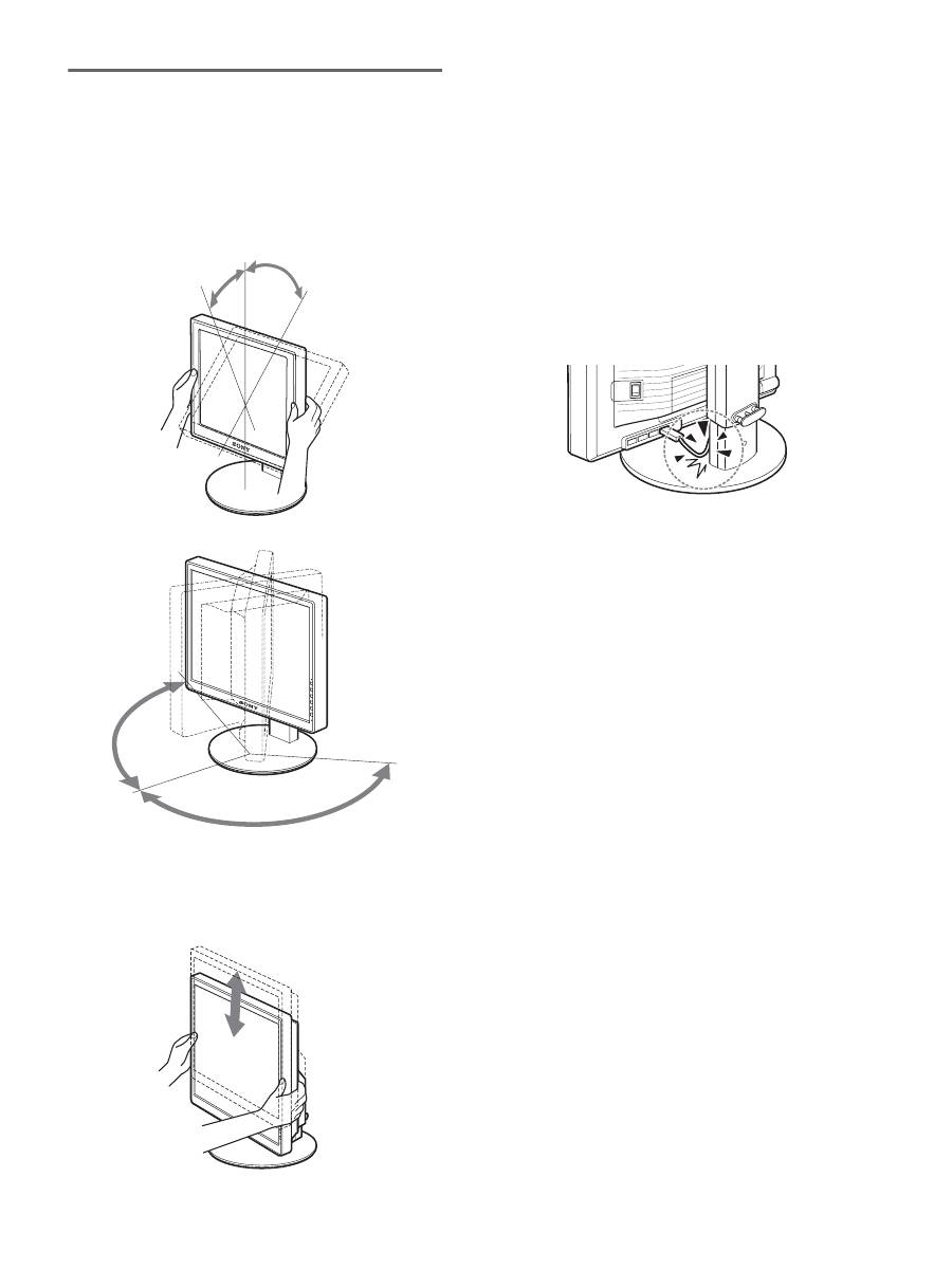
準備
8
:ディスプレイの向きと
高さを変える
下図の範囲でディスプレイの向きを変えられます。
ディスプレイ両側を持ち、ディスプレイの向きを調整す
る。
下図の範囲でディスプレイの高さを変えられます。
ディスプレイ両側を持ち、ディスプレイの高さを調整す
る。
ディスプレイをより快適にお使いいただくために
机や椅子の高さに合わせて、ディスプレイが反射しない見
やすい角度に調整してください。
ご注意
•
ディスプレイの向きを調整するときは、ディスプレイやケーブ
ル類および
USB
周辺機器を周りのものにぶつけないよう、静
かに動かしてください。
•
ディスプレイの高さを調整するときは、ディスプレイの下にも
のを置かないでください。誤ってぶつけると破損することがあ
ります。
• USB
機器または
USB
の周辺機器を取り付けた場合、スタンド
に当たらないように注意してください。大きさによっては、ディ
スプレイの向きや高さを変えると破損することがあります。
(
USB
端子があるモデルのみ)
約
5
°
約
20
°
約
175
°
約
175
°
高さ調整スタンド
約
110 mm
ピボットスタンド
約
130 mm
12
画面を縦
/
横に切り換えて使う
(ピボットスタンド付きモデルの
み)
お使いのコンピュータに、画像の縦
/
横を切り換える機能
があるときは、ディスプレイの向きを
90
度回転させて使
うことができます。
コンピュータ側で画像を切り換える設定を行ってから、
ディスプレイの向きを変えてください。
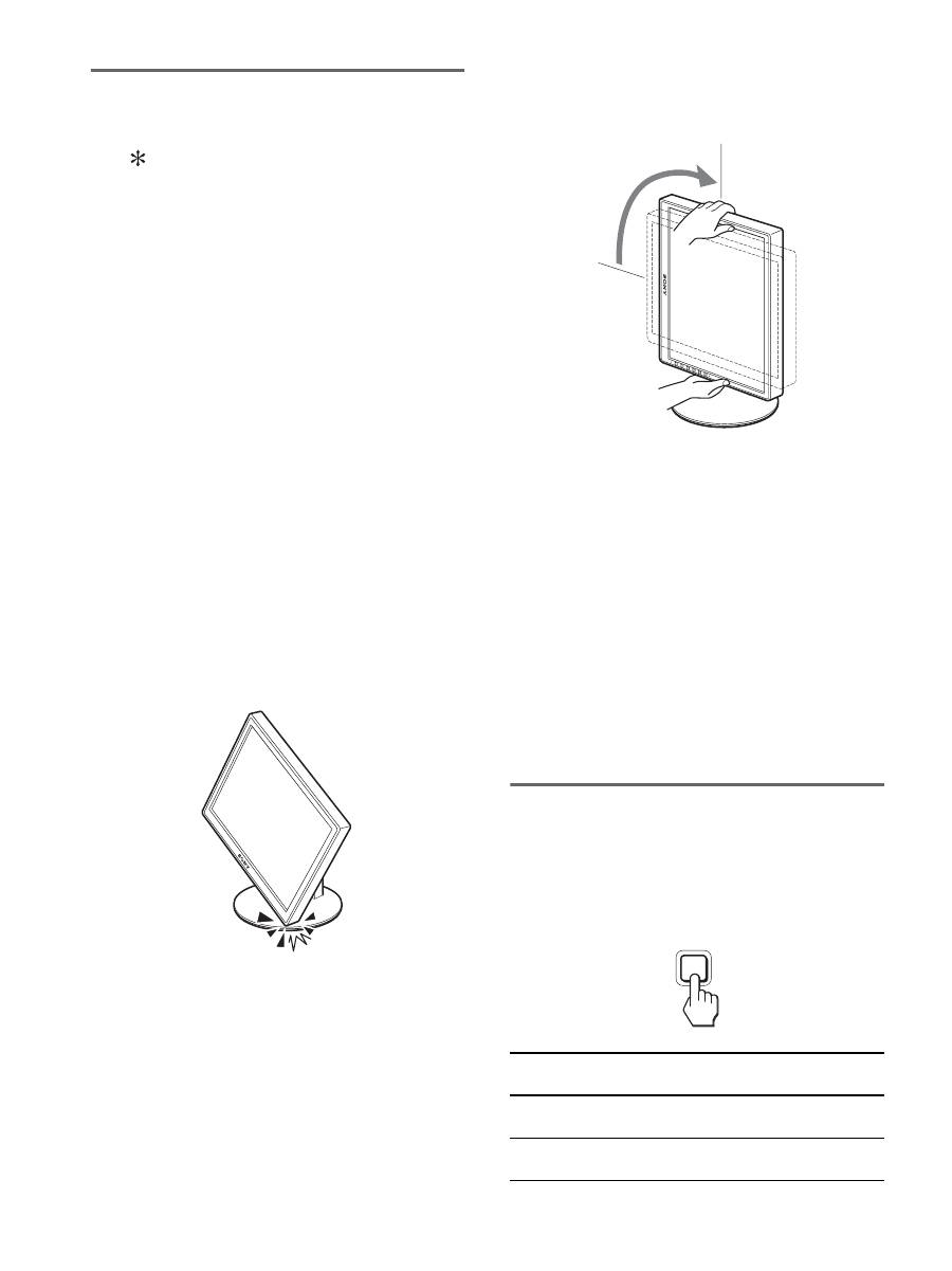
ディスプレイを縦向きで使うには
1
お使いのコンピュータ側で、画像を左回りに
90
度回転
させる設定をする。
2
ディスプレイのメニューボタンを押し、メニューの「オ
プション」から「メニュー回転機能」を選び、「縦」を
選ぶ。
メニュー表示の向きを、画面の向きに合わせて変更で
きます。
3
ディスプレイの両側を持ち、ゆっくりと一番上まで引
き上げる。
ご注意
•USB
機器または
USB
対応の周辺機器を取り付けたまま、
ディスプレイを回転させると、破損することがあります。
•
ディスプレイを回転させるときは、ディスプレイやケーブル
類および
USB
周辺機器を周りのものにぶつけないよう、静
かに動かしてください。
•
ディスプレイを回転させるときは、ケーブル類をケーブルホ
ルダーからいったん外し、ケーブルに力が加わらないよう、
注意しながら動かしてください。
4
ディスプレイの両側を持ち、ゆっくりと右回りに
90
度
回転させる。
90
度以上回転させることはできません。
5
ディスプレイの両側を持ち、ディスプレイの高さや向
きを調整する。
ディスプレイを横向きに戻すには
1
お使いのコンピュータ側で、画像を右回りに
90
度回転
させる設定をする。
2
ディスプレイのメニューボタンを押し、メニューの「オ
プション」から「メニュー回転機能」を選び、「横」を
選ぶ。
メニュー表示を横表示に戻します。
3
ディスプレイの両側を持ち、ゆっくりと一番上まで引
き上げる。
4
ディスプレイの両側を持ち、ゆっくりと左回りに
90
度
回転させる。
入力を切り換えるには
(
INPUT1/INPUT2
)
OK
ボタンを押す。
押すたびに、下表のように入力が切り換わります。
画面表示
(左上に約
5
秒表示)
以下につないだ入力に
切り換わります。
入力
1
:
DVI-D
INPUT1
用
DVI-D
入力端子
(デジタル
RGB
)
入力
2
:
HD15
INPUT2
用
HD15
入力端子
(アナログ
RGB
)
INPUT
OK
13
調整する
メニューを使って、いろいろな調整や設定ができます。
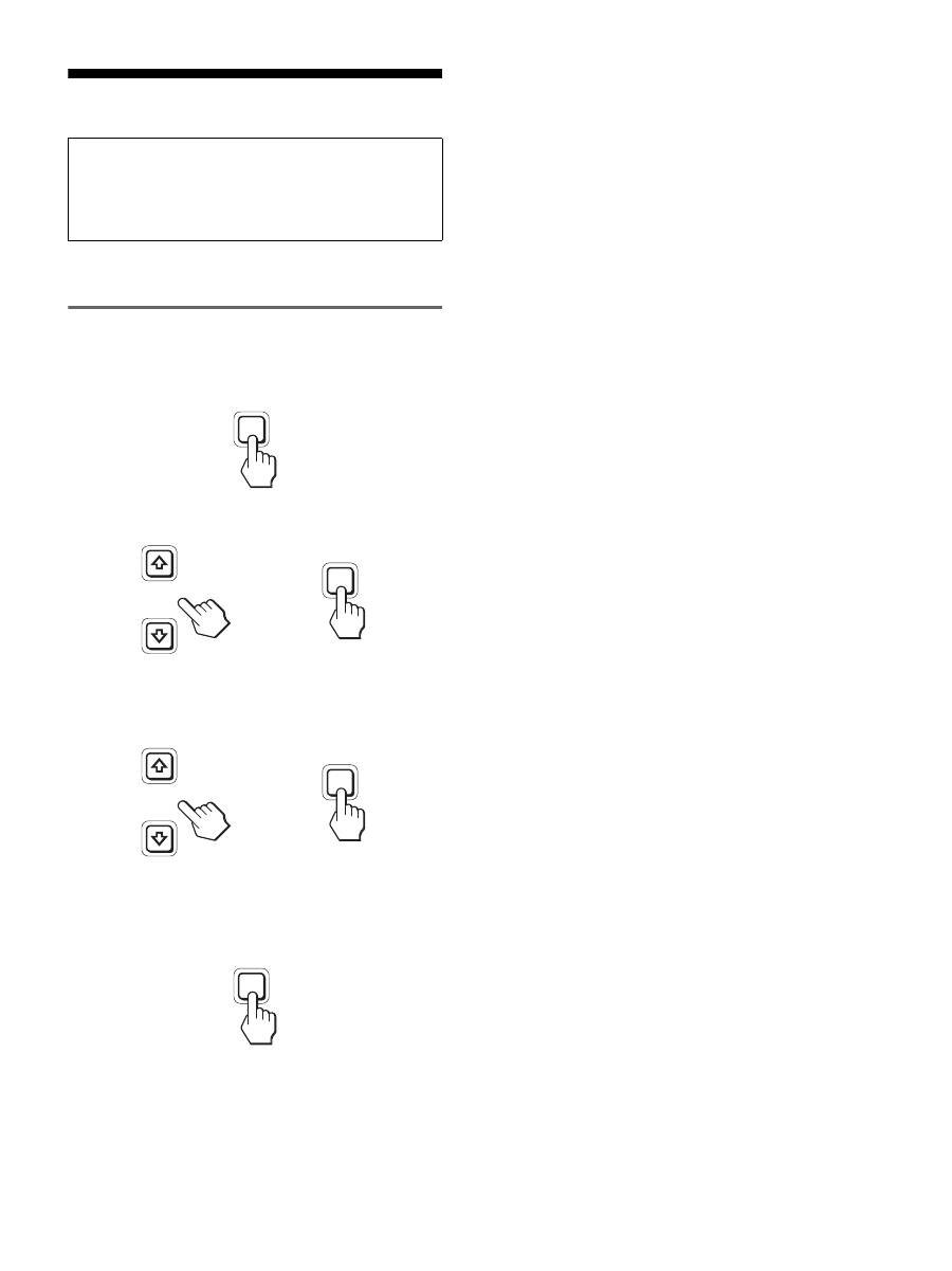
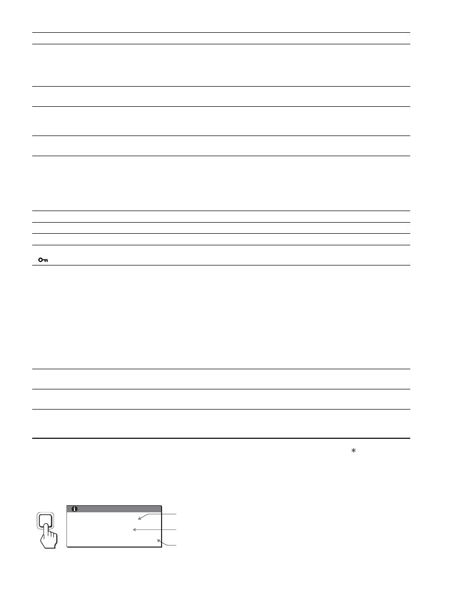
メニュー操作のしかた
1
メニュー画面を出す。
MENU
ボタンを押して、メニュー画面を出す。
2
調整したいメニューや項目を選ぶ。
m
/
M
ボタンを押して選び、
OK
ボタンを押して決定する。
3
調整する。
m
/
M
ボタンを押して調整し、
OK
ボタンを押す。
OK
ボタンを押すと、調整値が設定されて前の画面に
戻ります。
4
メニューを消す。
MENU
ボタンを押すと、メニュー画面が消える。
ボタンを押さなくても、調整後、約
45
秒たつと自動的
に消えます。
x
お買い上げ時の状態に戻す
リセット画面を使います。詳しくは、
0
(リセット)
(
17
ページ)をご覧ください。
調整を始める前に
本機とコンピュータをつなぎ、両方の電源を入れ、
30
分以上経過してから調整してください。最適な調整がで
きます。
MENU
INPUT
OK
,
,
INPUT
OK
MENU
14
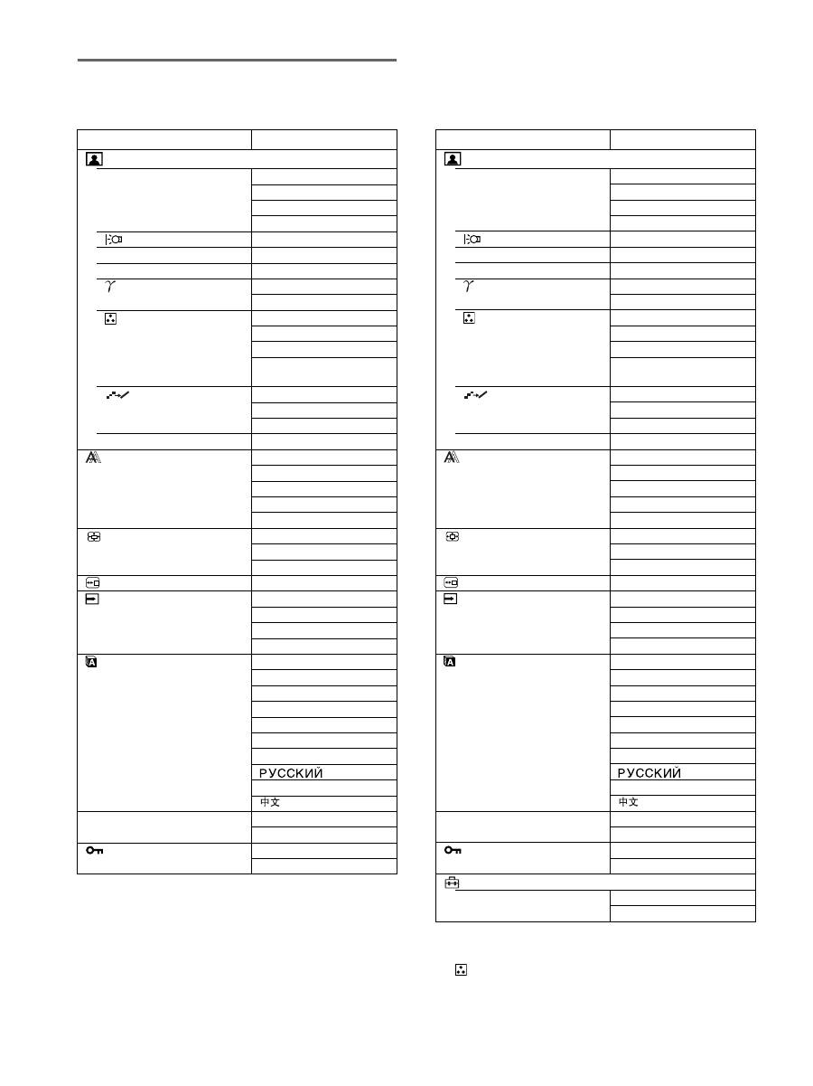
メニュー一覧
●のついたものは、そのモデルで使うことができる機能です。
1)
ECO
モードが「
AUTO
」に設定されているときは、バックラ
イト輝度は調整できません。
2)
(色温度)で
sRGB
が選択されているときは、コントラス
ト、ブライトネスおよびガンマは調整できません。
SDM-S205F
画質調整メニュー
MODE (ECO
モード)
HIGH
MIDDLE
LOW
AUTO
1)
バックライト輝度
●
1)
6
コントラスト
●
1) 2)
8
ブライトネス
●
2)
ガンマ
ユーザー
2)
CAL.
2)
色温度
9300K
6500K
sRGB
2)
ユーザー
(ゲインとバイアス)
スムージング
テキスト
スタンダード
グラフィック
0
モードリセット
●
画調整メニュー
オート
フェーズ
ピッチ
水平位置
垂直位置
ズームメニュー
フル
縦横比キープ
リアル
メニュー位置メニュー
●
自動入力センサー
メニュー
オン
入力
1
入力
2
オフ
LANGUAGE
メニュー
ENGLISH
FRANÇAIS
DEUTSCH
ESPAÑOL
ITALIANO
NEDERLANDS
SVENSKA
日本語
0
リセットメニュー
OK
キャンセル
メニューロックメニュー
オン
オフ
SDM-S205K
画質調整メニュー
MODE (ECO
モード)
HIGH
MIDDLE
LOW
AUTO
1)
バックライト輝度
●
1)
6
コントラスト
●
1) 2
)
8
ブライトネス
●
2
)
ガンマ
ユーザー
2
)
CAL.
2
)
色温度
9300K
6500K
sRGB
2
)
ユーザー
(ゲインとバイアス)
スムージング
テキスト
スタンダード
グラフィック
0
モードリセット
●
画調整メニュー
オート
フェーズ
ピッチ
水平位置
垂直位置
ズームメニュー
フル
縦横比キープ
リアル
メニュー位置メニュー
●
自動入力センサー
メニュー
オン
入力
1
入力
2
オフ
LANGUAGE
メニュー
ENGLISH
FRANÇAIS
DEUTSCH
ESPAÑOL
ITALIANO
NEDERLANDS
SVENSKA
日本語
0
リセットメニュー
OK
キャンセル
メニューロックメニュー
オン
オフ
オプションメニュー
メニュー回転
横
縦
15
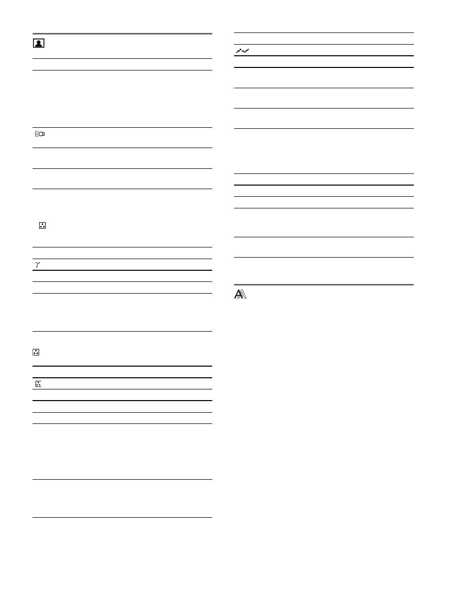
画質調整メニュー
ご注意
•
ECO
モードが「
AUTO
」に設定されているときは、バックラ
イト輝度は調整できません。
•
(色温度)で
sRGB
が選択されているときは、コントラス
ト、ブライトネスは調整できません。
ご注意
(色温度)で
sRGB
が選択されているときは、ガンマは調整できません。
1)
つないでいるコンピュータやその他の機器が
sRGB
に対応して
いないときは、
sRGB
カラー設定に調整されません。
「
sRGB
」を選ぶと、コントラスト、ブライトネス、ガンマは調
整できません。
ECO
モードが「
AUTO
」に設定されていると、
「
sRGB
」は選
べません。
ご注意
解像度が
1600
×
1200
の信号では、スムージング機能は働きま
せん。
画調整メニュー(アナログ
RGB
信号のみ)
x
自動画質調整機能
本機は、信号を受信したときに、自動的に画像の位置と鮮
明さ(フェーズ
/
ピッチ)を調整して、最適な画像を表示
します(
18
ページ)。
ご注意
自動画質調整機能が働いている間は、
1
(電源)スイッチ以外は
操作できません。
自動画質調整機能で完全に調整されていないと感じたと
きは
現在入力中の信号に合わせて再度自動で調整し直せます
(下記のオート)。
さらに微調整したいときは
手動で、鮮明さ(フェーズ
/
ピッチ)や位置(水平位置
/
垂直位置)を調整し直せます。
「オート」や「フェーズ
/
ピッチ」、「水平位置
/
垂直位置」
で設定した調整値は記憶されて、同じ信号が入力される
と、記憶した調整値になります。
メニュー項目
M
ボタンを押す
m
ボタンを押す
MODE
ECO
モードを設定します。
画面の明るさを
HIGH
、
MIDDLE
、
LOW
、
AUTO
から選べ、消費電力を
節約できます。さらに、入力ごとに異
なるモードを設定できます。
HIGH
MIDDLE
LOW
AUTO
バックライ
ト輝度
画面が明るくなり
ます。
画面が暗くなりま
す。
6
コントラスト 画像の明暗の差が
強くなります。
画像の明暗の差が
弱くなります。
8
ブライトネス 画像(黒レベル)
が明るくなります。
画像(黒レベル)
が暗くなります。
メニュー項目
ガンマ
選択項目
機能
ユーザー
画像の色合いを、調整できます。
CAL.
パネル自体のもつガンマカーブモード
です。お手持ちのカラーマネジメント
ツールをお使いいただくことで最適な
カラー設定が可能です。
メニュー項目
色温度
選択項目
機能
9300K
青みがかかった白色
6500K
赤みがかかった白色
sRGB
1
)
「
sRGB
」を選ぶと、色合いは
sRGB
カ
ラー設定に調整されます。(
sRGB
カ
ラー設定は、業界標準のコンピュータ機
器用色空間プロトコルです。)「
sRGB
」
を選んだ場合、お使いのコンピュータも
sRGB
プロファイルにしてください。
ユーザー
画面の明るい部分(ゲイン:白レベル)
と暗い部分(バイアス:黒レベル)を
微調整できます。また、調整した値は
記憶されます。
メニュー項目
スムージング
選択項目
機能
テキスト
文字を鮮明に表示します(ワープロや
表計算ソフト用)。
スタンダード
標準的なスムージング効果で表示しま
す。
グラフィック
画像をよりなめらかに表示します(写
真やイラスト用)。
メニュー項目
0
モードリセット
選択項目
機能
OK
バックライト輝度、コントラスト、ブ
ライトネス、ガンマおよび色温度をお
買い上げ時の設定に戻します。
キャンセル
リセットが実行されないまま、メニュー
画面に戻ります。
16
コンピュータをつなぎ換えるなどで入力信号を変えたと
きには、もう一度調整が必要になることがあります。
x
手動で鮮明さや画像の位置を調整し直す
文字や画像が鮮明でないとき、画像が真ん中に出ないとき
に調整します。この調整は、コンピュータがディスプレイ
の
HD15
入力端子(アナログ
RGB
)に接続されていると
きに有効です。
1
解像度をコンピュータ側で
1600
×
1200
に設定する。
2 CD-ROM
を入れる。
3 CD-ROM
を起動して、テストパターンを表示する。
Windows
の場合
CD-ROM
が自動で起動したとき
1
地域とモデルを選んで、「ディスプレイアジャストメン
トツール(
Utility
)」をクリックする。
2
「
Adjust
」をクリックし、解像度を確認して「
Next
」を
クリックする。
ピッチ、フェーズ、水平位置・垂直位置の順にテストパ
ターンが出ます。
CD-ROM
が自動で起動しないとき
1
マイ・コンピュータを開き、
CD-ROM
アイコンを右ク
リックして「エクスプローラ」から
CD-ROM
を開く。
2
[Utility]
を開いて、
[Windows]
を選ぶ。
3
[Win_Utility.exe]
を起動する。
テストパターンが出ます。
Macintosh
の場合
1
[Utility]
を開き、
[Mac]
を選ぶ。
2
[Mac_Utility.exe]
を起動する。
テストパターンが出ます。
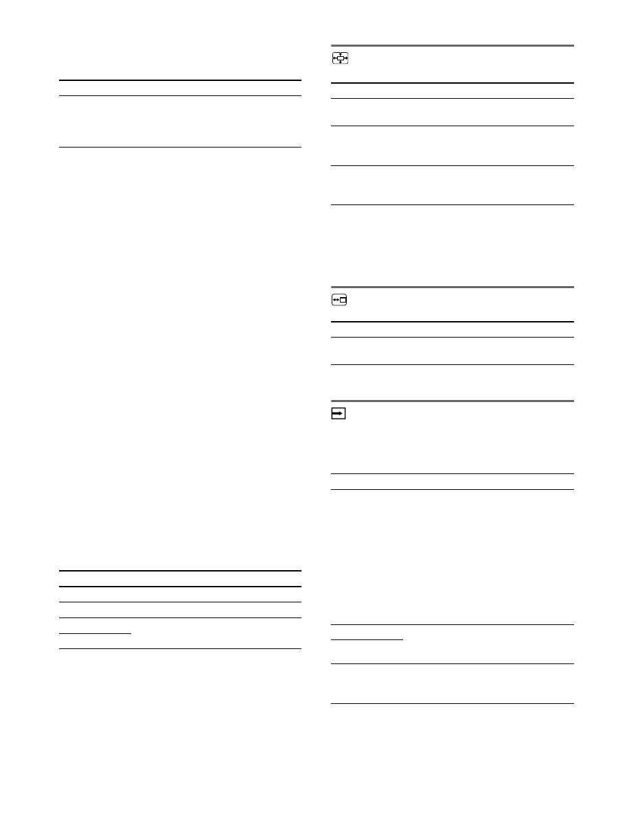
ズームメニュー
ご注意
解像度が
1600
×
1200
の信号では、この設定はできません。
常に画面いっぱいに表示されます。
メニュー位置メニュー
自動入力センサーメニュー
入力信号の有無を検知して、自動的に入力を切り換えるこ
とができます。
メニュー項目
機能
オート
フェーズ、ピッチ、水平位置、垂直位
置の設定を、現在入力されている信号
に最適な調整値にして、その調整値を
記憶します。
メニュー項目
m
/
M
ボタンを押す
フェーズ
横縞を最少になるように調整します。
ピッチ
縦縞を最少になるように調整します。
水平位置
テストパターンの外周の枠が全部、画
面に入るように調整します。
垂直位置
メニュー項目
機能
フル
信号の種類や解像度にかかわらず、画
像を画面いっぱいに表示します。
縦横比キープ
信号の縦横比で拡大表示します。
信号によっては、画面上下の端に黒い
帯がでます。
リアル
信号本来の解像度で表示します。
1600
×
1200
未満の信号は画面の中央に表
示され、周囲は黒い枠になります。
メニュー項目
m
/
M
ボタンを押す
メニュー位置
メニューの表示位置を変えられます。
9
か所があらかじめ設定されています。
メニュー項目
機能
オン
選んでいる入力端子への入力信号がな
いときや、
OK
ボタンで入力信号がな
い入力端子を選んだときは、画面に表
示メッセージが出て(
19
ページ)、他
の入力端子への入力信号があるかを自
動的に確認し、入力を自動的に切り換
えます。
入力が切り換わると、切り換わった入
力が画面の左上に表示されます。
入力信号がない場合は、本機は省電力
状態になります。
入力
1
電源を入れたときに、入力1または入
力2が優先的に表示されます(自動入
力センサーは働きません)。
入力
2
オフ
入力は自動的に切り換わりません。
OK
ボタンを押して、入力を切り換え
てください。
17
LANGUAGE
メニュー
0
リセットメニュー(お買い上
げ時の設定に戻す)
メニューロック
オプションメニュー
機能
省電力機能(パワーセーブ機能)
本機は、
VESA
、
NUTEK
および
E
NERGY
S
TAR
のパ
ワーセービングガイドラインに対応しています。アナロ
グ入力では
DPMS
(
Display Power Management
Standard
)、デジタル入力では
DMPM
(
DVI Digital
Monitor Power Management
)に対応しているコン
ピュータやグラフィックボードにつなぐと、操作をして
いないときは自動的に次のような省電力状態になります。
1)
コンピュータが省電力状態になると、信号が入力されなくなる
ため、アクティブオフ状態になる前に「
NO INPUT SIGNAL
」
と表示が出ます。約
5
秒後、本機も省電力状態になります。
「デ ィ ー プ ス リ ー プ」は、
EPA
(
Environmental Protection
Agency
)の定めた待機時の消費電力抑制状態です。
節電しながら使う
(
ECO
モード)
本機前面にある
ECO
ボタンをくり返し押すと、画面の明
るさが変わります。
各設定が表示されて、画面の明るさが変わります。表示は
約
5
秒後に消えます。
HIGH
→
MIDDLE
→
LOW
の順番に画面の明るさが落
ち、消費電力を節約できます。
お買い上げ時の状態では、画面の明るさは「
HIGH
」に設
定されています。
メニュー項目
m
/
M
ボタンを押す
ENGLISH
FRANÇAIS
DEUTSCH
ESPAÑOL
ITALIANO
NEDERLANDS
SVENSKA
日本語
英語
フランス語
ドイツ語
スペイン語
イタリア語
オランダ語
スウェーデン語
ロシア語
中国語
メニュー項目
機能
OK
すべての調整値をお買い上げ時の設定に
戻します。ただし、(
LANGUAGE
メ
ニュー)の設定はリセットされません。
キャンセル
リセットが実行されないまま、メニュー
画面に戻ります。
メニュー項目
機能
オン
1
(電源)スイッチ以外の操作は、
「
」マークが出て操作できなくなり
ます。
オフ
「オン」を解除するときに選びます。
「オン」のときに
MENU
ボタンを押す
と、 (メニューロック)が自動的に選
択されます。
メニュー項目
メニュー回転
選択項目
機能
横
画面が横向き表示になります。
縦
画面が縦向き表示になります。
本機の状態
1
(電源)ランプ
通常動作時
緑点灯
アクティブオフ
1)
(ディープスリープ)
オレンジ点灯
1
(電源):切
赤点灯
主電源:切
消灯
E C O
L OW
:
E C O
AU TO
:
E C O
H I G H
:
E C O
M I D D L E
:
5 0
ECO
,

18
自動輝度調整機能
(ライトセンサー)
本機には、周囲の明るさに応じて画面の明るさを自動調整
する機能があります。本機前面の
ECO
ボタン、または
MENU
の画質調整メニューで、
ECO
モードを「
AUTO
」
にすることにより、画面の明るさを自動的に最適な状態に
調整します。お買い上げ時の状態では、画面の明るさは
「
HIGH
」に設定されています。さらに、本機前面の
ECO
ボタンから、
ECO
モードを「
AUTO
」に設定したときに
表示される調節バーを
m
/
M
ボタンで変更することにより、
お好みに応じた自動調整のレベル(明るめ、暗めなど)を
調整可能範囲内において設定することができます。
自動画質調整機能
(アナログ
RGB
信号のみ)
本機は、信号を受信したときに、自動的に画像の位
置と鮮明さ(フェーズ
/
ピッチ)を調整して、最適
な画像を表示します。
お買い上げ時に設定されている表示モード
本機には、入力信号に合わせて最適な画質で表示できるよ
うに、代表的な表示モードがお買い上げ時に設定されてい
ます。信号が表示モードと同じであれば、自動的にあらか
じめ設定された最適な調整値で表示されます。
表示モード以外の信号のときは
下記の周波数の間であれば、信号をはじめて受信したとき
に自動画質調整機能が働いて、きれいな画像を表示しま
す。
水平周波数:
28
〜
92 kHz
(アナログ
RGB
)
28
〜
75 kHz
(デジタル
RGB
)
垂直周波数:
48
〜
85 Hz
(アナログ
RGB
)
60 Hz
(デジタル
RGB
)
信号を初めて受信したときには、画面表示までに通常より
時間がかかることがありますが、この調整値は自動的に本
機に記憶され、次からは表示モードの信号と同様に動作す
るようになります。
手動でフェーズやピッチ、画像の位置を調整したと
きは
入力信号によって自動調整機能だけでは完全に調整でき
ないときは、手動で調整できます(
16
ページ)。手動で調
整すると、すべての表示モードにおいて、手動で調整した
調整値がユーザーモードとして記憶され、同じ信号が入力
されるたびに、その調整値が選ばれるようになります。
ご注意
自動画質調整機能が働いている間は、
1
(電源)スイッチ以外は
操作できません。
KVM
機能
(
Keyboard-Video-Mouse
機能)
USB
マウスと
USB
キーボードを本機につなぐこ
とにより、
2
台までのコンピュータを
INPUT/OK
ボタン(
8
ページ)で切り換えながら使うことがで
きます。
USB
端子について
•
本機の
USB
端子には、
USB
マウスと
USB
キーボード
をつなぐことを推奨します。それ以外の機器を本機につ
ないでも、正しく動作しない場合があります。また、
Bluetooth
対応の機器は、正しく動作しないことがあり
ます。
•
本機の
USB
端子は、
USB Full-Speed (Max 12 Mbps)
に対応しています。
ご注意
•
INPUT/OK
ボタンを押しても、すぐにコンピュータが切り換
わらない場合があります。
•
最新の
USB
ドライバをインストールして使用してください。
古いドライバのままでは、
USB
機器が動作しないことがあり
ます。
•
USB
ハブを使用するときは、自動入力センサーメニューでオ
フに設定してください。
19
故障かな?と思ったら
お買い上げ店などにご相談いただく前に、次の事項をご確
認ください。
表示メッセージについて
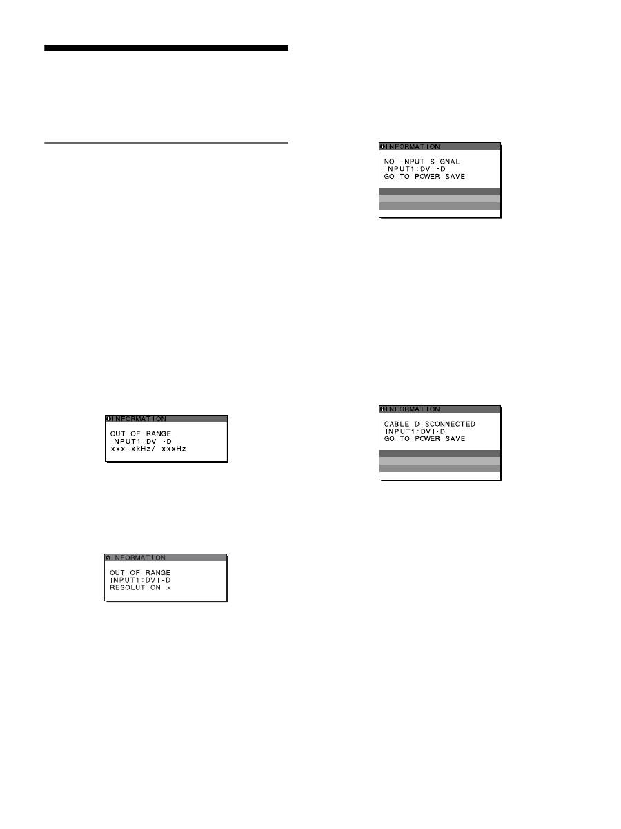
入力信号が正しくないときは、画面に次のような表示メッ
セージが出ます。この場合は、「本機の症状と対処のしか
た」(
20
ページ)に従ってください。
「
OUT OF RANGE
」
と表示されている場合
入力信号の周波数が、本機の仕様に合っていません。以下
を確認してください。
詳しくは、「本機の症状と対処のしかた」(
20
ページ)を
ご覧ください。
xxx.x kHz / xxx Hz
と表示されている場合
水平または垂直周波数が、本機の仕様に合っていませ
ん。
数字の部分に現在入力されている信号の水平
/
垂直周波
数が表示されます。
例:
RESOLUTION
>
1600
×
1200
と表示されている場合
解像度が、本機の仕様(
1600
×
1200
以下)に合っていま
せん。
例:
「
NO INPUT SIGNAL
」
と表示されている場合
現在選んでいる入力端子の入力信号がありません。
自動入力センサー(
16
ページ)がオンに設定されている
ときは、他の入力端子からの入力信号をさがし、自動的に
入力を切り換えます。
例:
入力信号が見つからないときは、
「
GO TO POWER SAVE
」
というメッセージが表示されてから約
5
秒後に省電力
状態に入ります。
「
CABLE DISCONNECTED
」
と表示されている場合
現在選んでいる入力端子のビデオ信号ケーブルがはずれ
ています。
自動入力センサー(
16
ページ)がオンに設定されている
ときは、他の入力端子からの入力信号をさがし、自動的に
入力を切り換えます。
例:
入力信号が見つからないときは、
「
GO TO POWER SAVE
」
というメッセージが表示されてから約
45
秒後に省電力
状態に入ります。
1 6 0 0 X 1 2 0 0

20
本機の症状と対処のしかた
本機以外(コンピュータなど)が原因の場合は、接続機器の取扱説明書をご覧ください。
こんなときは
原因と対処のしかた
画像が出ない。
1
(電源)ランプが点灯し
ていない。または、
1
(電
源)スイッチを押しても
1
(電源)ランプが点灯し
ない
°
•
電源コードをつなぎ直す。
•
主電源を入れる(
10
ページ)
1
(電源)ランプが赤色ま
たはオレンジ色に点灯し
ている。
•
1
(電源)スイッチで電源を入れる。
「
CABLE
DISCONNECTED
」とい
う警告表示が出ている。
•
ビデオ信号ケーブルを正しくつなぐ(
7
ページ)。
•
ビデオ信号ケーブルのピンが曲がっている。まっすぐに直すか、別のケーブルを使う。
•
入力切り換えが正しいか確認する(
12
ページ)。
•
付属品ではないビデオ信号ケーブルを使っている。付属品ではないビデオ信号ケーブル
を使っていると、「
CABLE DISCONNECTED
」と表示が出ることがあります。故障
ではありません。
「
NO INPUT SIGNAL
」
という警告表示が出てい
る。または
1
(電源)ラン
プがオレンジ色に点灯し
ている。
•
ビデオ信号ケーブルを正しくつなぐ(
7
ページ)。
•
ビデオ信号ケーブルのピンが曲がっている。まっすぐに直すか、別のケーブルを使う。
•
入力切り換えが正しいか確認する(
12
ページ)。
x
本機以外(コンピュータなど)が原因の場合
•
コンピュータが省電力状態になっている。キーボードのキーのどれかを押してみるか、
マウスを動かしてみる。
•
コンピュータのグラフィックボードが正しくバススロットに差し込まれているか確認す
る。
•
コンピュータの電源を入れる。
•
コンピュータを再起動する。
「
OUT OF RANGE
」とい
う警告表示が出ている
(
19
ページ)。
x
本機以外(コンピュータなど)が原因の場合
•
入力信号の周波数が、本機の仕様に合っていない。本機をつなぐ前につないでいたディ
スプレイがあるときは、そのディスプレイにつなぎ換えて、画像が出るか確認する。画
像が出たら、コンピュータで以下の範囲に設定する。
水平周波数:
28
〜
92 kHz
(アナログ
RGB
)、
28
〜
75 kHz
(デジタル
RGB
)
垂直周波数:
48
〜
85 Hz
(アナログ
RGB
)、
60 Hz
(デジタル
RGB
)
解像度:
1600
×
1200
以下
Windows
を使用してい
る。
•
本機をつなぐ前につないでいたディスプレイがあるときは、そのディスプレイにつなぎ
換えて、画像が出るか確認する。画像が出たら、以下を行う。
Windows
のデバイス選
択画面で製造元に
SONY
を選び、本機の型名を選ぶ。本機の型名が表示されないとき
は、「プラグ
アンド
プレイ」を選ぶ。
Macintosh
とつないでい
る。
•
必要に応じて市販のアダプタをお使いください。アダプタは、先にコンピュータに差し
込んでから、ビデオ信号ケーブルにつなぎます。
画像が乱れる、ゆれる、ちら
つく。
•
ピッチとフェーズを調整する(アナログ
RGB
信号のみ)(
16
ページ)。
•
離れたところにある他の電源につないでみる。
x
本機以外(コンピュータなど)が原因の場合
•
コンピュータのグラフィックボードで、本機が正しく設定されているかを確認する。
•
入力信号のグラフィックモード(
VESA
、
Macintosh19
"
カラーなど)と周波数が、本
機で使用できる範囲かを確認する。ただし本機で使用できる範囲でも、グラフィック
ボードによっては同期パルス幅が合わないため、きれいに画像を映せないことがありま
す。
•
本機はインターレース信号には対応していません。プログレッシブ信号になるように設
定してください。
•
コンピュータのリフレッシュレート(垂直周波数)を、最適な画面になるように設定す
る。
21
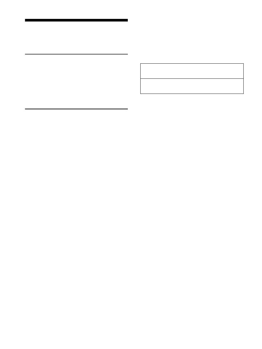
本機の情報(インフォメーション)を表示する
信号を入力しているときに、
INFORMATION
画面が出る
まで
MENU
ボタンを
5
秒以上押したままにする。
もう一度、
MENU
ボタンを押すと消えます。
例:
本機の安全規格上の型名は
SDM-S205
ですが、販売上の
型名および取扱説明書での型名は
SDM-S205F/S205K
と
なります。
故障のときは、お買い上げ店またはソニーサービス窓口にご連絡く
ださい。また、お問い合わせのときは次のことをお知らせください。
•
型名:
•
製造番号:
•
故障の状態:できるだけ詳しく
•
購入年月日:
•
つないでいるコンピュータ、およびグラフィックボードの仕様
と名前:
•
入力信号の種類(アナログ
RGB/
デジタル
RGB
):
こんなときは
原因と対処のしかた
画像がくっきりしていない。
•
コントラストやブライトネスを調整する(
15
ページ)。
•
ピッチとフェーズを調整する(アナログ
RGB
信号のみ)(
16
ページ)。
x
本機以外(コンピュータなど)が原因の場合
•
コンピュータで解像度を
1600
×
1200
に設定する。
画像が二重、三重になる。
•
ビデオ信号ケーブルの延長コードやスイッチャーボックスの使用をやめる。
•
接続ケーブルを端子にしっかりと差し込む。
画像の位置がずれている、または画
像の大きさが正しくない。(アナログ
RGB
信号のみ)
•
ピッチとフェーズを調整する(
16
ページ)。
•
画像の位置を調整する(
16
ページ)。入力信号やグラフィックボードによって
は、画像が画面全体に広がらないことがあります。
画像が小さい。
x
本機以外(コンピュータなど)が原因の場合
•
コンピュータで解像度を
1600
×
1200
に設定する。
画像が暗い。
•
バックライトを調整する(
15
ページ)。
•
ブライトネスを調整する(
15
ページ)。
•
ガンマを調整する(
15
ページ)。
•
電源を入れたあと、画面が明るくなるまでしばらく時間がかかります。
• ECO
ボタンを押した後は、
ECO
モードの設定によっては、画面が暗くなるこ
ともあります。
画面に波模様や縦縞が出る。
•
ピッチとフェーズを調整する(アナログ
RGB
信号のみ)(
16
ページ)。
色むらがある。
•
ピッチとフェーズを調整する(アナログ
RGB
信号のみ)(
16
ページ)。
白色が白く見えない。
•
色温度を調整する(
15
ページ)。
本機のボタンが働かない。
(
マークが画面に出る)
•
「メニューロック」が「オン」になっている。「オフ」にする(
17
ページ)。
USB
ケーブルでつないだ機器が動作
しない。
• USB
ケーブル(付属)を正しくつないでいるか確認する(
8
ページ)。
•
主電源スイッチおよび
1
(電源)スイッチを押して、本機の電源を入れる。
x
コンピュータなど本機につないでいる機器が原因の場合
•
つないでいる機器の電源が入っているか確認する。
•
最新の
USB
ドライバをコンピュータにインストールし直す。詳しくは、つない
だ機器のメーカーにお問い合わせください。
•
キーボードやマウスでコンピュータを操作できないときは、キーボードやマウス
をコンピュータに直接つなぎ、コンピュータを再起動してから
USB
接続の設定
をする。その後、本機につなぎ直す。本機の
USB
端子を経由してコンピュー
タ、キーボード、マウスをつなぐと、最初にコンピュータを起動したときに、コ
ンピュータをマウスやキーボードから操作できないことがあります。
しばらくすると、ディスプレイの電
源が切れてしまう。
x
コンピュータなど本機につないでいる機器が原因の場合
•
コンピュータの省電力設定をオフにする。
メニュー画面上の解像度表示が正し
くない。
•
グラフィックボードの設定によっては、メニュー画面上の解像度表示とコン
ピュータでの設定が一致しないことがあります。
主電源を切っても、
1
(電源)ラン
プがしばらく点灯している。
•
主電源が入っていて
1
(電源)スイッチを押していない状態、または省電力状態
のときに、
MAIN POWER
(主電源)スイッチを切ると、
1
(電源)ランプがす
ぐに消灯しない場合があります。故障ではありません。
INFORMATION
MODEL : SDM-S205F
SER. NO : 1234567
MANUFACTURED : 2005-52
MENU
機種名
製造番号
製造年と週
22
保証書とアフターサー ビス
保証書
•
この製品は保証書が添付されていますので、お買い上げ
の際、お買い上げ店でお受け取りください。
•
所定事項の記入および記載内容をお確かめのうえ、大切
に保存してください。
•
保証期間は、お買い上げ日より
3
年間です。
アフターサービスについて
調子が悪いときはまずチェックを
b
「故障かな?と思ったら」の項を参考にして、故障かどう
かをお調べください。
それでも具合が悪いときはサービス窓口へ
b
お買い上げ店、または添付の「ソニーご相談窓口のご案
内」にある、お近くのソニーサービス窓口にご相談くだ
さい。
保証期間中の修理は
b
保証書の記載内容に基づいて修理させていただきます。
くわしくは保証書をご覧ください。
保証期間経過後の修理は
b
修理によって機能が維持できる場合は、ご要望により有
料で修理させていただきます。
部品の保有期間について
当社では、コンピュータディスプレイの補修用性能部品
(製品の機能を維持するために必要な部品)を、製造打ち
切り後
8
年間保有しています。この部品保有期間を修理可
能の期間とさせていただきます。
保有期間が経過した後も、故障箇所によっては、修理可能
の場合がありますので、お買い上げ店か、サービス窓口に
ご相談ください。
ご相談になるときは次のことをお知らせください。
型名:ディスプレイが梱包されていた箱や本体後面の
ID
ラベルをご覧になり、お使いのディスプレイの型名をご確
認ください。
製造番号:
故障の状態:できるだけ詳しく
購入年月日:
This display is designed for use in Japan only and
cannot be used in any other country.
お買い上げ店
TEL.
お近くのサービスステーション
TEL.
23
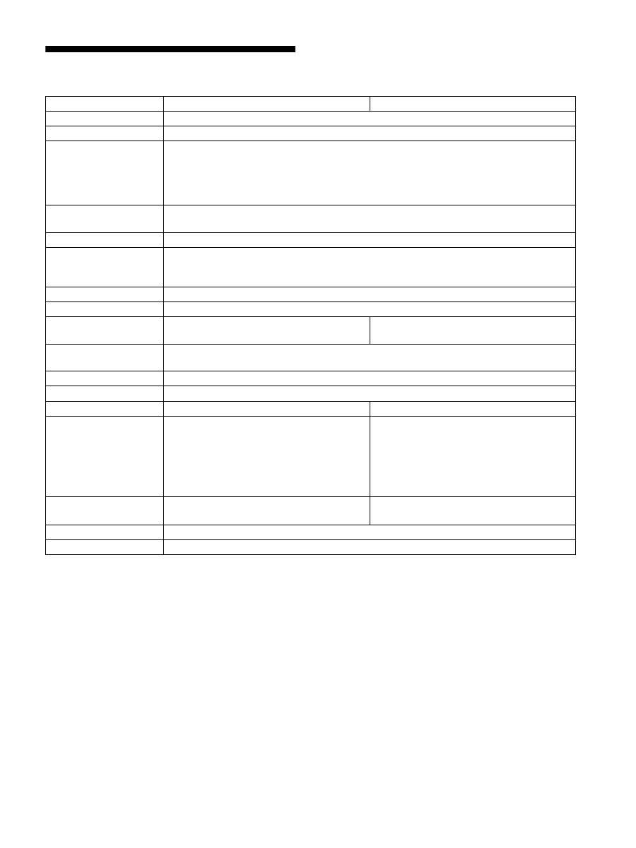
主な仕様
1)
推奨周波数タイミング
•
水平同期幅率:水平周波数のタイミングの合計の
4.8%
以上、
または
0.8
mμs のどちらか大きい方
•
水平ブランキング幅:
2.5
μs 以上
•
垂直ブランキング幅:
450
μs 以上
本機の仕様および外観は、改良のため予告なく変更するこ
とがありますが、ご了承ください。
型名
SDM-S205F
SDM-S205K
LCD
パネル
a-Si TFT
アクティブマトリックス
画面サイズ
20.1
インチ(
51 cm
)
入力信号フォーマット
RGB
動作周波数
1)
水平:
28
〜
92 kHz
(アナログ
RGB
)
28
〜
75 kHz
(デジタル
RGB
)
垂直:
48
〜
85 Hz
(アナログ
RGB
)
60 Hz
(デジタル
RGB
)
解像度
水平:最大
1600
ドット
垂直:最大
1200
ライン
入力信号の種類
デジタル×
1
アナログ×
1
入力信号レベル
アナログ
RGB
信号:
0.7 Vp-p
、
75
Ω
、正極性
同期信号:
TTL
レベル、
2.2
kΩ
、極性自由
デジタル
RGB
(
DVI
)信号:
TMDS
(
Single link
)
音声入力
ステレオミニジャック、
0.5 Vrms
音声出力
ステレオミニジャック
USB
端子
−
USB Full-Speed (Max12 Mbps)
A
ポート×
4
、
B
ポート×
2
、
電源
AC100
〜
240 V/50-60 Hz
最大
1.2 A
消費電力量
最大
55 W
動作温度
5
〜
35
℃
スタンドの種類
高さ調整スタンド
ピボットスタンド
最大外形寸法
(幅
/
高さ
/
奥行き)
約
441.5
×
410.5 - 520.5
×
277.5 mm
(
スタンド付
)
約
441.5
×
356.5
×
74 mm
(
スタンドなし
)
約
441.5
×
421 - 551
×
277.5 mm
(
スタンド付
(
標準使用時
))
約
356.5
×
470.5 - 600.5
×
277.5 mm
(
スタンド付
(
回転使用時
))
約
441.5
×
356.5
×
74 mm
(
スタンドなし
)
質量
約
9.6 kg (
スタンド付
)
約
6.0 kg (
スタンドなし
)
約
9.9 kg (
スタンド付
)
約
6.1 kg (
スタンドなし
)
プラグ
&
プレイ機能
DDC2B
付属品
6
ページをご覧ください。

i
TCO’99 Eco-document (for the black
model)
x
Congratulations!
You have just purchased a TCO’99 approved and labelled product! Your
choice has provided you with a product developed for professional use.
Your purchase has also contributed to reducing the burden on the
environment and also to the further development of environmentally
adapted electronics products.
x
Why do we have environmentally labelled com-
puters?
In many countries, environmental labelling has become an established
method for encouraging the adaptation of goods and services to the
environment. The main problem, as far as computers and other electronics
equipment are concerned, is that environmentally harmful substances are
used both in the products and during their manufacture. Since it is not so
far possible to satisfactorily recycle the majority of electronics equipment,
most of these potentially damaging substances sooner or later enter nature.
There are also other characteristics of a computer, such as energy
consumption levels, that are important from the viewpoints of both the
work (internal) and natural (external) environments. Since all methods of
electricity generation have a negative effect on the environment (e.g.
acidic and climate-influencing emissions, radioactive waste), it is vital to
save energy. Electronics equipment in offices is often left running
continuously and thereby consumes a lot of energy.
x
What does labelling involve?
This product meets the requirements for the TCO’99 scheme which
provides for international and environmental labelling of personal
computers. The labelling scheme was developed as a joint effort by the
TCO (The Swedish Confederation of Professional Employees), Svenska
Naturskyddsforeningen (The Swedish Society for Nature Conservation)
and Statens Energimyndighet (The Swedish National Energy
Administration).
Approval requirements cover a wide range of issues: environment,
ergonomics, usability, emission of electric and magnetic fields, energy
consumption and electrical and fire safety.
The environmental demands impose restrictions on the presence and use
of heavy metals, brominated and chlorinated flame retardants, CFCs
(freons) and chlorinated solvents, among other things. The product must
be prepared for recycling and the manufacturer is obliged to have an
environmental policy which must be adhered to in each country where the
company implements its operational policy.
The energy requirements include a demand that the computer and/or
display, after a certain period of inactivity, shall reduce its power
consumption to a lower level in one or more stages. The length of time to
reactivate the computer shall be reasonable for the user.
Labelled products must meet strict environmental demands, for example,
in respect of the reduction of electric and magnetic fields, physical and
visual ergonomics and good usability.
Below you will find a brief summary of the environmental requirements
met by this product. The complete environmental criteria document may
be ordered from:
TCO Development
SE-114 94 Stockholm, Sweden
Fax: +46 8 782 92 07
Email (Internet): development@tco.se
Current information regarding TCO’99 approved and labelled
products may also be obtained via the Internet, using the address:
http://www.tco-info.com/
x
Environmental requirements
Flame retardants
Flame retardants are present in printed circuit boards, cables, wires,
casings and housings. Their purpose is to prevent, or at least to delay the
spread of fire. Up to 30% of the plastic in a computer casing can consist
of flame retardant substances. Most flame retardants contain bromine or
chloride, and those flame retardants are chemically related to another
group of environmental toxins, PCBs. Both the flame retardants
containing bromine or chloride and the PCBs are suspected of giving rise
to severe health effects, including reproductive damage in fish-eating
birds and mammals, due to the bio-accumulative* processes. Flame
retardants have been found in human blood and researchers fear that
disturbances in foetus development may occur.
The relevant TCO’99 demand requires that plastic components weighing
more than 25 grams must not contain flame retardants with organically
bound bromine or chlorine. Flame retardants are allowed in the printed
circuit boards since no substitutes are available.
Cadmium
**
Cadmium is present in rechargeable batteries and in the colour-generating
layers of certain computer displays. Cadmium damages the nervous
system and is toxic in high doses. The relevant TCO’99 requirement states
that batteries, the colour-generating layers of display screens and the
electrical or electronics components must not contain any cadmium.
Mercury
**
Mercury is sometimes found in batteries, relays and switches. It damages
the nervous system and is toxic in high doses. The relevant TCO’99
requirement states that batteries may not contain any mercury. It also
demands that mercury is not present in any of the electrical or electronics
components associated with the labelled unit.
CFCs (freons)
The relevant TCO’99 requirement states that neither CFCs nor HCFCs
may be used during the manufacture and assembly of the product. CFCs
(freons) are sometimes used for washing printed circuit boards. CFCs
break down ozone and thereby damage the ozone layer in the stratosphere,
causing increased reception on earth of ultraviolet light with e.g. increased
risks of skin cancer (malignant melanoma) as a consequence.
Lead
**
Lead can be found in picture tubes, display screens, solders and
capacitors. Lead damages the nervous system and in higher doses, causes
lead poisoning. The relevant TCO’99 requirement permits the inclusion of
lead since no replacement has yet been developed.
*
Bio-accumulative is defined as substances which accumulate within
living organisms.
** Lead, Cadmium and Mercury are heavy metals which are Bio-
accumulative.

ii
TCO’03 Eco-document (for the silver
model)
x
Congratulations!
The display you have just purchased carries the TCO’03
Displays label. This means that your display is designed,
manufactured and tested according to some of the strictest
quality and environmental requirements in the world. This
makes for a high performance product, designed with the
user in focus that also minimizes the impact on our natural
environment.
x
Ergonomics
• Good visual ergonomics and image quality in order to
improve the working environment for the user and to
reduce sight and strain problems. Important parameters
are luminance, contrast, resolution, reflectance, colour
rendition and image stability.
x
Energy
• Energy-saving mode after a certain time – beneficial
both for the user and the environment
• Electrical safety
x
Emissions
• Electromagnetic fields
• Noise emissions
x
Ecology
• The product must be prepared for recycling and the
manufacturer must have a certified environmental
management system such as EMAS or ISO 14 001
• Restrictions on
- chlorinated and brominated flame retardants and
polymers
- heavy metals such as cadmium, mercury and lead.
The requirements included in this label have been
developed by TCO Development in co-operation with
scientists, experts, users as well as manufacturers all over
the world. Since the end of the 1980s TCO has been
involved in influencing the development of IT equipment
in a more user-friendly direction. Our labelling system
started with displays in 1992 and is now requested by users
and IT-manufacturers all over the world.
For more information, please visit
www.tcodevelopment.com
Recycling Information
x
Customer in Europe
The collection and recycling of this product has been planned
according to your country’s relevant legislation. To ensure that
this product will be collected and recycled in way that minimizes
the impact on the environment, please do the following:
1. If you purchased this product for private use, contact your
municipality or the waste collection system and bring the
product to this collection point / have the product be picked up
by the waste collection system. Alternatively, your retailer
might take back this if you purchase new equivalent equipment;
please check with your retailer whether he will take back this
product before bringing it. For information on your country’s
recycling arrangements, please contact the Sony representation
in your country (contact details at: www.sony-europe.com).
Further details on specific recycling systems can be found at the
following addresses:
- Belgium: www.recupel.be
- Netherlands: www.nvmp.nl (consumer electronics)
www.ictmilieu.nl (IT equipment)
- Norway: www.elretur.no
- Sweden: www.el-kretsen.se
- Switzerland: www.swico.ch
2. If you use this product professionally, check the product’s
delivery contract for take back / recycling arrangements and
follow the procedures described therein. Alternatively, follow
the procedures described under point 1.
x
Customer in USA
We Sony as a member of EIA recommends to visit URL below
http://www.eiae.org/
x
Customer in Asia
http://www.sony.co.jp/SonyInfo/Environment/recycle/3R.html

2-649-019-
04
(1)
© 2005 Sony Corporation
TFT LCD Color Computer Display
SDM-S205
2
Owner’s Record
The model and serial numbers are located at the rear of the unit.
Record these numbers in the spaces provided below. Refer to them
whenever you call upon your dealer regarding this product.
Model No. Serial No.
To reduce the risk of fire or electric shock, do not
expose this apparatus to rain or moisture.
Dangerously high voltages are present inside the
unit. Do not open the cabinet. Refer servicing to
qualified personnel only.
FCC Notice
This equipment has been tested and found to comply with the limits
for a Class B digital device, pursuant to Part 15 of the FCC Rules.
These limits are designed to provide reasonable protection against
harmful interference in a residential installation. This equipment
generates, uses, and can radiate radio frequency energy and, if not
installed and used in accordance with the instructions, may cause
harmful interference to radio communications. However, there is no
guarantee that interference will not occur in a particular installation.
If this equipment does cause harmful interference to radio or
television reception, which can be determined by turning the
equipment off and on, the user is encouraged to try to correct the
interference by one or more of the following measures:
– Reorient or relocate the receiving antenna.
– Increase the separation between the equipment and receiver.
– Connect the equipment into an outlet on a circuit different from
that to which the receiver is connected.
– Consult the dealer or an experienced radio/TV technician for help.
You are cautioned that any changes or modifications not expressly
approved in this manual could void your authority to operate this
equipment.
Be sure to confirm the carton that came with your display. The ID
label of your display model is located at the rear of the display.
(for the black model)
(for the silver model)
WARNING
IMPORTANTE
Para prevenir cualquier mal funcionamiento y evitar daños, por
favor, lea detalladamente este manual de instrucciones antes
de conectar y operar este equipo.
If you have any questions about this product, you may call;
Sony Customer Information Services Center 1-800-222-7669
or http://www.sony.com/
Declaration of Conformity
Trade Name
: SONY
Model
: SDM-S205
Note
: means any number or alphanumeric
character.
Responsible Party
: Sony Electronics Inc.
Address
: 16530 Via Esprillo, San Diego, CA
92127 U.S.A.
Telephone Number : 858-942-2230
This device complies with part 15 of the FCC rules. Operation is
subject to the following two conditions: (1) This device may not
cause harmful interference, and (2) this device must accept any
interference received, including interference that may cause
undesired operation.
NOTICE
This notice is applicable for USA/Canada only.
If shipped to USA/Canada, install only a UL LISTED/CSA
LABELLED power supply cord meeting the following
specifications:
SPECIFICATIONS
Plug Type
Nema-Plug 5-15p
Cord
Type SVT or SJT, minimum 3
×
18 AWG
Length
Maximum 15 feet
Rating
Minimum 7 A, 125 V
NOTICE
Cette notice s’applique aux Etats-Unis et au Canada
uniquement.
Si cet appareil est exporté aux Etats-Unis ou au Canada, utiliser
le cordon d’alimentation portant la mention UL LISTED/CSA
LABELLED et remplissant les conditions suivantes:
SPECIFICATIONS
Type de fiche
Fiche Nema 5-15 broches
Cordon
Type SVT ou SJT, minimum 3
×
18 AWG
Longueur
Maximum 15 pieds
Tension
Minimum 7 A, 125 V
As an
E
NERGY
S
TAR Partner, Sony
Corporation has determined that this
product meets the
E
NERGY
S
TAR
guidelines for energy efficiency.
This monitor complies with the
TCO’99 guidelines.
This monitor complies with the
TCO’03 guidelines.

Table of Contents
• Macintosh is a trademark licensed to
Apple Computer, Inc., registered in the
U.S.A. and other countries.
• Windows
®
is registered trademarks of
Microsoft Corporation in the United
States and other countries.
• IBM PC/AT and VGA are registered
trademarks of IBM Corporation of the
U.S.A.
• VESA and DDC
™
are trademarks of the
Video Electronics Standards
Association.
•
E
NERGY
S
TAR is a U.S. registered
mark.
• Adobe and Acrobat are trademarks of
Adobe Systems Incorporated.
• All other product names mentioned
herein may be the trademarks or
registered trademarks of their respective
companies.
• Furthermore, “
™
” and “
®
” are not
mentioned in each case in this manual.
3
GB
http://www.sony.net/
Precautions. . . . . . . . . . . . . . . . . . . . . . . . . . . . . . . . . . . . . . . . . . . . 4
Checking the model name of the display . . . . . . . . . . . . . . . . . . . . . 5
Identifying parts and controls . . . . . . . . . . . . . . . . . . . . . . . . . . . . . . 5
Setup . . . . . . . . . . . . . . . . . . . . . . . . . . . . . . . . . . . . . . . . . .6
Setup 1:
Assemble the stand . . . . . . . . . . . . . . . . . . . . . . . . . . . . . . 6
Setup 2:
Connect the video signal cables . . . . . . . . . . . . . . . . . . . . 7
Setup 3:
Connect the USB mouse or the USB keyboard
or other devices (USB port-equipped models only). . . . . . 8
Setup 4:
Connect the audio cords . . . . . . . . . . . . . . . . . . . . . . . . . . 9
Setup 5:
Connect the power cord . . . . . . . . . . . . . . . . . . . . . . . . . . 9
Setup 6:
Secure the cords and close the connector cover . . . . . . . 9
Setup 7:
Turn on the display and computer . . . . . . . . . . . . . . . . . . 10
Setup 8:
Adjust the tilt and height . . . . . . . . . . . . . . . . . . . . . . . . . 11
Switching your picture to portrait/landscape
(For the Pivot Stand attached models only) . . . . . . . . . . . . . . . . . . 12
Selecting the input signal (INPUT1/INPUT2) . . . . . . . . . . . . . . . . . 12
Customizing Your Display . . . . . . . . . . . . . . . . . . . . . . .13
Navigating the menu. . . . . . . . . . . . . . . . . . . . . . . . . . . . . . . . . . . . 13
Menu options list. . . . . . . . . . . . . . . . . . . . . . . . . . . . . . . . . . . . . . . 14
PICTURE ADJUST menu. . . . . . . . . . . . . . . . . . . . . . . . . . . . . 15
SCREEN menu (analog RGB signal only) . . . . . . . . . . . . . . . 15
ZOOM menu . . . . . . . . . . . . . . . . . . . . . . . . . . . . . . . . . . . . . . 16
MENU POSITION menu . . . . . . . . . . . . . . . . . . . . . . . . . . . . . 16
INPUT SENSING menu . . . . . . . . . . . . . . . . . . . . . . . . . . . . . . 16
LANGUAGE menu . . . . . . . . . . . . . . . . . . . . . . . . . . . . . . . . . . 17
0
RESET menu (reset to the default setting) . . . . . . . . . . . . . . . 17
MENU LOCK menu . . . . . . . . . . . . . . . . . . . . . . . . . . . . . . . . . 17
OPTION menu . . . . . . . . . . . . . . . . . . . . . . . . . . . . . . . . . . . . 17
Technical Features . . . . . . . . . . . . . . . . . . . . . . . . . . . . .17
Power saving function. . . . . . . . . . . . . . . . . . . . . . . . . . . . . . . . . . . 17
Reducing the power consumption (ECO mode) . . . . . . . . . . . . . . . 17
Automatic brightness adjustment function (light sensor) . . . . . . . . 18
Automatic picture quality adjustment function
(analog RGB signal only) . . . . . . . . . . . . . . . . . . . . . . . . . . . . . . . . 18
KVM function (Keyboard-Video-Mouse function) . . . . . . . . . . . . . . 18
Troubleshooting. . . . . . . . . . . . . . . . . . . . . . . . . . . . . . . .19
On-screen messages . . . . . . . . . . . . . . . . . . . . . . . . . . . . . . . . . . . 19
Trouble symptoms and remedies . . . . . . . . . . . . . . . . . . . . . . . . . . 20
Specifications. . . . . . . . . . . . . . . . . . . . . . . . . . . . . . . . . .23
TCO’99 Eco-document (for the black model) . . . . . . . . . . . . . . . . . . .i
TCO’03 Eco-document (for the silver model) . . . . . . . . . . . . . . . . . . ii
4
Precautions
Warning on power connections
• Use the supplied power cord. If you use a different power cord,
be sure that it is compatible with your local power supply.
For the customers in the U.S.A.
If you do not use the appropriate cord, this display will not
conform to mandatory FCC standards.
For the customers in the UK
If you use the display in the UK, be sure to use the appropriate
UK power cord.
Installation
Do not install or leave the display:
• In places subject to extreme temperatures, for example near a
radiator, heating vent, or in direct sunlight. Subjecting the
display to extreme temperatures, such as in an automobile
parked in direct sunlight or near a heating vent, could cause
deformations of the casing or malfunctions.
• In places subject to mechanical vibration or shock.
• Near any equipment that generates a strong magnetic field,
such as a TV or various other household appliances.
• In places subject to inordinate amounts of dust, dirt, or sand, for
example near an open window or an outdoor exit. If setting up
temporarily in an outdoor environment, be sure to take
adequate precautions against airborne dust and dirt. Otherwise
irreparable malfunctions could occur.
Be careful not to touch the air vents on the upper rear of the
display, since they become heated.
Handling the LCD screen
• Do not leave the LCD screen facing the sun as it can damage
the LCD screen. Take care when you place the display by a
window.
• Do not push on or scratch the LCD screen. Do not place a heavy
object on the LCD screen. This may cause the screen to lose
uniformity or cause LCD panel malfunctions.
• If the display is used in a cold place, a residual image may
appear on the screen. This is not a malfunction. The screen
returns to normal as the temperature rises to a normal operating
level.
• If a still picture is displayed for a long time, a residual image
may appear for a while. The residual image will eventually
disappear.
• The LCD panel becomes warm during operation. This is not a
malfunction.
Note on the LCD (Liquid Crystal Display)
Please note that the LCD screen is made with high-
precision technology. However, black points or bright
points of light (red, blue, or green) may appear
constantly on the LCD screen, and irregular colored
stripes or brightness may appear on the LCD screen.
This is not malfunction.
(Effective dots: more than 99.99%)
Maintenance
• Be sure to unplug the power cord from the power outlet before
cleaning your display.
• Clean the LCD screen with a soft cloth. If you use a glass
cleaning liquid, do not use any type of cleaner containing an
anti-static solution or similar additive as this may scratch the
LCD screen’s coating.
• Clean the cabinet, panel, and controls with a soft cloth lightly
moistened with a mild detergent solution. Do not use any type
of abrasive pad, scouring powder, or solvent, such as alcohol or
benzine.
• Do not rub, touch, or tap the surface of the screen with sharp or
abrasive items such as a ballpoint pen or screwdriver. This type
of contact may result in a scratched picture tube.
• Note that material deterioration or LCD screen coating
degradation may occur if the display is exposed to volatile
solvents such as insecticide, or if prolonged contact is
maintained with rubber or vinyl materials.
Transportation
• Disconnect all the cables from the display. If you use a height
adjustable stand adjust its height to the highest position and
hold both sides of the LCD display securely. Be careful not to
scratch the screen when transporting. If you drop the display,
you may injured or the display may be damaged.
• When you transport this display for repair or shipment, use the
original carton and packing materials.
• Replace the stopper pin for the height adjustable stand to fix the
stand during the transportation.
Disposal of the display
• Do not dispose of this display with general
household waste.
• The fluorescent tube used in this display contains
mercury. Disposal of this display must be carried out
in accordance to the regulations of your local
sanitation authority.
For customers in the United States
This product contains mercury. Disposal of this product may be
regulated if sold in the United States. For disposal or recycling
information, please contact your local authorities or the
Electronics Industries Alliance (http://www.eiae.org).
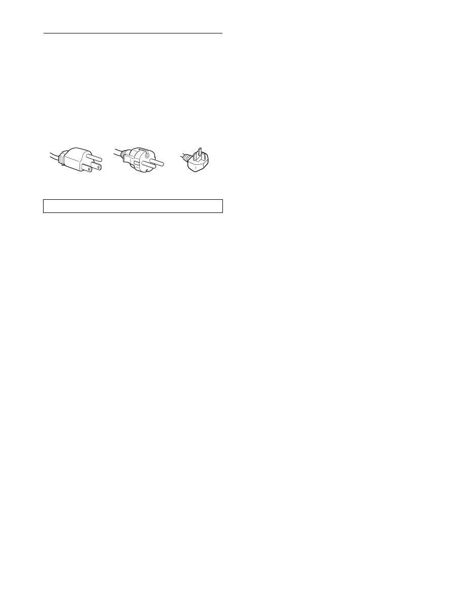
The equipment should be installed near an easily accessible outlet.
Example of plug types
for 100 to 120 V AC
for 200 to 240 V AC
for 240 V AC only
5
GB
Checking the model name of the
display
Check the model name of the display first.
The model name is located at the rear of the display (Example:
SDM-S205F).
You cannot use some of the functions or menu options for
certain display models.
Identifying parts and controls
See the pages in parentheses for further details.
The illustration only shows one of all the models that are available
for this display.
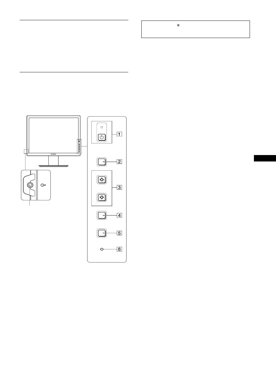
1
1
(Power) switch and
1
(power) indicator
(pages 10, 17)
This switch turns the display on when
1
(power) indicator is
red. To turn the display off, press this switch again.
If the
1
(power) indicator fails to light, press the MAIN
POWER switch (
8
).
2
MENU button (page 13)
This button turns the menu screen on and off.
3
m
/
M
buttons (page 13)
These buttons are used to select the menu items and make
adjustments.
4
OK button (page 13)
This button activates the selected menu item and adjustments
made using the
m
/
M
buttons (
3
).
INPUT
(page 12)
These buttons switch the video input signal between INPUT1
and INPUT2 when two computers are connected to the
display. (Only available when menu is turned off.)
5
ECO button (page 17)
This button is used to reduce the power consumption.
When the menu screen is not displayed, you can also
automatically adjust the picture quality for the current input
signal while keeping pressing this button for more than 3
seconds (One touch Auto adjust). (analog RGB signal only)
6
Light sensor (page 18)
This sensor measures the brightness of the area surrounding
the display. Be sure not to cover the sensor with paper, etc.
7
Audio output jack (page 9)
This jack outputs audio signals to speakers or other audio
equipment.
MENU
INPUT
ECO
OK
7
Front of the display
The contents with mark for specifications vary
depending on the models. For details, see “Specifications”
(page 23).

6
Rear of the display
8
MAIN POWER switch (page 10)
This switch is to turn the MAIN POWER button of the display
on and off.
9
AC IN connector (page 9)
This connector connects the power cord (supplied).
0
DVI-D input connector (digital RGB) (page 8)
This connector inputs digital RGB video signals that comply
with DVI Rev.1.0.
qa
HD15 input connector (analog RGB) (page 8)
This connector inputs analog RGB video signals (0.700 Vp-p,
positive) and sync signals.
qs
Cable holder (page 9)
This part secures cables and cords to the display.
qd
USB downstream port (USB port-equipped models
only) (page 8)
Connecting the USB mouse and USB keyboard to the display,
you can connect up to two computers to the display switching
the input back and forth.
qf
USB upstream port (USB port-equipped models only)
Connect the USB cable to your computer and display.
qg
Security lock hole
The Kensington Micro Saver Security System should be used
for the security lock hole.
Micro Saver Security System is a trademark of Kensington.
qh
Audio Jack for INPUT1
This jack inputs audio signals when connected to the audio
output jack of a computer or other audio equipment connected
to INPUT1.
qj
Audio Jack for INPUT2
This jack inputs audio signals when connected to the audio
output jack of a computer or other equipment connected to
INPUT2.
Setup
Before using your display, check that the following items are
included in your carton:
• LCD display
• Power cord
• Stand Base
• HD15-HD15 video signal cable (analog RGB)
• DVI-D video signal cable (digital RGB)
• Audio cord (stereo miniplug)
• USB cable
• CD-ROM (utility software for Windows/Macintosh, Operating
Instructions, etc.)
• Warranty card
• Quick Setup Guide
The contents with mark for specifications vary depending on
the models. For details, see “Specifications” (page 23).
Setup 1: Assemble the stand
x
When using supplied stand
1
Open the carton and take out the stand base.
2
Confirm the supplied items.
• With a screw attached to the bottom of Stand Base.
3
Put a soft mat or a like on a desk or a like.
You may damage the LCD screen and the display itself, if
putting the display directly on the desk.
4
Take the display out from the carton and then place
the frame of the laid display along the edge of the
desk.
qg
qs
qd
8
9
q; qh qaqj qf
Do not press the LCD screen when placing or raising
the display straight on a desk or a like.
It may affect the uniformity of the screen or damage
the LCD display.
Display
Stand
Soft mat or a like
7
GB
5
Hook the Stand Base holes onto the prongs of stand
to attach.
1
Lift the handle of screw to screw the stand base
securely.
2
Be sure that the screw is secured and turn the screw
handle back.
6
Remove the stopper pin after raising the height
adjustable stand straight.
Note
Do not remove the stopper pin while the stand is laid. It may fall or injure
you by the stand neck coming off from the Stand Base impetuously.
x
When using VESA Stand
You can attach a VESA stand in other brand by removing the
supplied stand attached to the display.
Setup 2: Connect the video signal
cables
1 Slide down the connector cover.
2 Tilt the display up.
And then move the display’s angle higher.
1
Stand Base
2
Screw
Stopper Pin
Screws
compatible with
VESA stand (4)
• Turn off the display and computer before connecting.
Notes
• Do not touch the pins of the video signal cable connector as this
might bend the pins.
• Check the alignment of the connector to avoid bending the pins of
the video signal cable connector.
Connector cover
8
3 Connect the video signal cables to the display.
x
Connect a computer equipped with an HD15
output connector (analog RGB)
Using the supplied HD15-HD15 video signal cable (analog
RGB), connect the computer to the display’s HD 15 input
connector (analog RGB).
x
Connect a computer equipped with a DVI
output connector (digital RGB)
Using the supplied DVI-D video signal cable (digital RGB),
connect the computer to the display’s DVI-D input connector
(digital RGB).
Setup 3: Connect the USB mouse
or the USB keyboard or
other devices (USB port-
equipped models only)
By connecting the USB mouse or the USB keyboard or other
devices, you can switch inputs back and forth (KVM function).
For more details, see “KVM function” (page 18).
If you are not using the USB mouse or the USB keyboard or other
devices on your display, go to Setup 4.
1
Connect the supplied cable between the display and
the computer.
2
Connect the USB mouse or the USB keyboard or
other devices to the display.
For Macintosh User:
If you connect the USB Downstream port to a Macintosh
keyboard with a power button, the power button on the
keyboard may fail to turn on. Turn on the power button on
your computer or connect the keyboard directly to your
computer and turn it on, and then connect the USB
Downstream port to the keyboard.
Notes
• The USB port of this display is compatible with Windows 2000 /
Windows XP Professional / Windows XP Home edition / Macintosh.
• If the USB mouse or the USB keyboard or other devices have already
connected to your computer, remove them once.
• This Setup is only designed for those computers and OS that are USB
compatible. For more details, refer to the operating instruction of your
computer or OS.
to the computer’s HD15 output
connector (analog RGB)
HD15-HD15 video signal
cable (analog RGB)
(supplied)
to the HD 15 input
connector (analog
RGB)
to the computer’s DVI output
connector (digital RGB)
DVI-D video signal cable
(digital RGB) (supplied)
to the DVI-D input
connector (digital RGB)
AC IN
DVI-D
HD15
1
2
2
1
To USB port to
Computer
To USB port to
Computer
USB cable
(supplied)
USB cable (supplied)
USB Mouse
USB
keyboard
2
2
1
1
9
GB
Setup 4: Connect the audio cords
If you are not intended to output audio, you do not need
this connection.
1
Connect the display’s audio input jack and audio
output jack of the computer or other audio
equipment using the supplied audio cord.
2
Connect the audio cable (not supplied) securely to
the display’s audio output jack.
Audio output will be changed when the display’s audio input and
audio output connection has been completed.
Connect audio equipment that is within the input range shown in
the display’s audio input specifications. Too high of an input may
cause damage to the display.
Setup 5: Connect the power cord
1
Connect the supplied power cord securely to the
display’s AC IN connector.
2
Connect the other end securely to a power outlet.
Setup 6: Secure the cords and
close the connector cover
1
Draw the cords and cables through the cable holder
as illustrated.
2
Close the connector cover.
Note
When bounding the cords and cables, be sure to loosen them a little. If
they get pulled hard they may come off from the connectors/plugs as you
adjust the display angle. If you stretch the cords and cables too hard they
may get damaged.
to the audio
input
to audio output of
the computer or
other audio
equipment
audio cord (supplied)
to the audio output
audio cable
(not supplied)
to AC IN
to a power outlet
power cord (supplied)
1
2
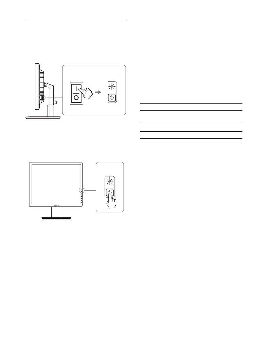
10
Setup 7: Turn on the display and
computer
1
Make sure that the
1
(power) Indicator blinks red. At
the time of your purchase, the MAIN POWER switch
is set to the
\
side.
Note
When the MAIN POWER switch on the right side of your display is not
set to the
\
side, press the
\
side and check that the
1
(power) indicator
blinks red.
2
Press the
1
(power) switch located on the front
right of the display.
The
1
(power) indicator lights up in green.
3
Turn on the computer.
If no picture appears on your screen
• Check that the power cord and the video signal cables are
properly connected.
• If “NO INPUT SIGNAL”
appears on the screen:
– The computer is in the power saving mode. Try pressing any
key on the keyboard or moving the mouse.
– Check that the input signal setting is correct by pressing the
OK button (page 12).
• If “CABLE DISCONNECTED”
appears on the screen:
– Check that the video signal cables are properly connected.
– Check that the input signal setting is correct by pressing the
OK button (page 12).
•
If “OUT OF RANGE”
appears on the screen:
Reconnect the old display. Then adjust the computer’s graphics
board within the following ranges.
For more information about the on-screen messages, see “Trouble
symptoms and remedies” on page 20.
No need for specific drivers
The display complies with the “DDC” Plug & Play standard and
automatically detects all the display’s information. No specific driver
needs to be installed to the computer.
The first time you turn on your computer after connecting the display, the
setup Wizard may appear on the screen. If this is the case, follow the on-
screen instructions. The Plug & Play display is automatically selected so
that you can use this display.
The vertical frequency turns to 60 Hz.
Since flickers are unobtrusive on the display, you can use it as is. You do
not need to set the vertical frequency to any particular high value.
MAIN POWER
lights in red
lights in green
Analog RGB
Digital RGB
Horizontal
frequency
28–92 kHz
28–75 kHz
Vertical
frequency
48–85 Hz
60 Hz
Resolution
1600
×
1200 or less
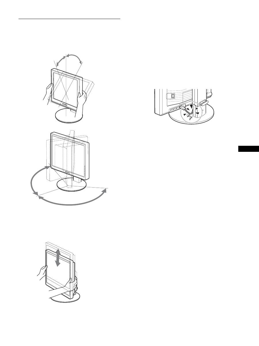
11
GB
Setup 8: Adjust the tilt and height
This display can be adjusted within the angles shown below.
Hold both sides of the LCD display, then adjust display
angles.
When you use the height adjustable stand, the height adjust is also
available as below.
Hold both sides of the LCD display, and then adjust the
display height.
To use the display comfortably
Adjust the viewing angle of your display according to the height
of your desk and chair so that light is not reflected from the
display to your eyes.
Notes
• When you adjust the display position, do not crash the display or cables
or other USB devices against objects around it. Be sure to move the
display quietly.
• Do not put any objects under the display when you adjust the height of
stand. It may get damaged by accident.
• When connecting USB products or USB devices to the display, be sure
not to crash them against the Stand Base. As adjusting the tilt and
height of the display, the display might get damaged depending on the
size of the products or devices. (USB port-equipped models only)
approx. 5°
approx. 20°
approx. 175°
approx.
175°
Height Adjustable Stand
approx. 110 mm
(4
11
/
32
inches)
Pivot Stand
approx. 130 mm
(5
1
/
8
inches)
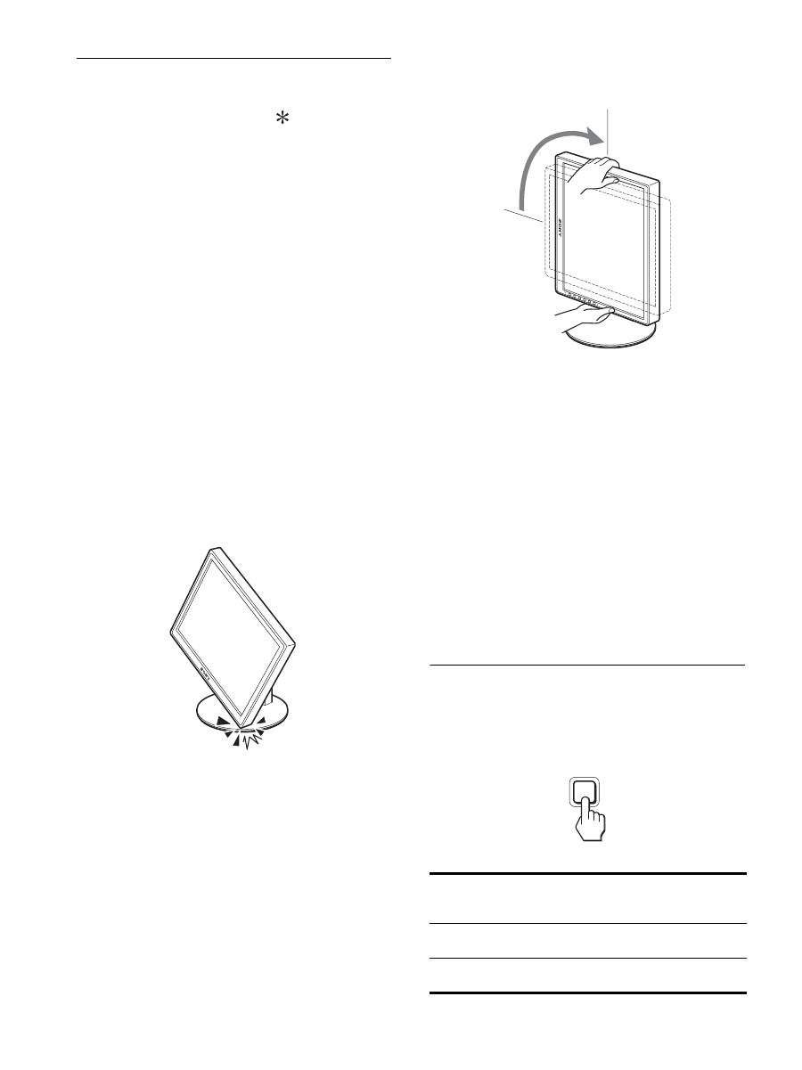
12
Switching your picture to portrait/
landscape (For the Pivot Stand
attached models only)
If your computer has a function to switch the screen to portrait/
landscape, you can rotate the screen 90
°
.
Adjust your setting to switch images on your computer first, then
rotate the screen.
Rotating the display to portrait
1
Adjust the setting on your computer to rotate the
screen 90° anti-clockwise.
2
Press the MENU button of the display, and then
select “MENU ROTATION” from the OPTION Menu,
and select “PORTRAIT.”
You can change the menu display position according to the
screen position.
3
Hold both sides of the display and raise it slowly to
the highest position.
Notes
• If you rotate the display connected to the USB device or the USB
compatible products, you may damage the display.
• If you rotate the display, do not crash the display or cables or other
USB devices against objects around it. Be sure to move the display
quietly.
• When you rotate your display remove all the cables from the cable
holder, then move them carefully without pulling them hard.
4
Hold both sides of the display, and rotate it 90°
clockwise slowly.
You cannot rotate the display larger than 90
°
.
5
Hold both sides of the display, and adjust the height
and tilt of the display.
To set back the display to the flat position
1
Adjust the setting on your computer to rotate the
screen 90° clockwise.
2
Press the MENU button of the display, and then
select “MENU ROTATION” from the OPTION Menu,
and select “LANDSCAPE.”
Set back the menu display to the flat position.
3
Hold both sides of the display and raise it to the
highest position slowly.
4
Hold both sides of the display, and rotate it 90°
anti-clockwise slowly.
Selecting the input signal (INPUT1/
INPUT2)
Press the OK button.
The input signal changes every time you press the OK button.
On-screen message
(Appears about 5 seconds on
the upper left corner.)
Input signal configuration
INPUT1 : DVI-D
DVI-D input connector
(digital RGB) for INPUT1
INPUT2 : HD15
HD15 input connector
(analog RGB) for INPUT2
INPUT
OK

13
GB
Customizing Your Display
You can make numerous adjustments to your display using the
on-screen menu.
Navigating the menu
1
Display the main menu.
Press the MENU button to display the main menu on your
screen.
2
Select the menu you want to adjust.
Press the
m
/
M
buttons to display the desired menu. Press the
OK button to select the menu item.
3
Adjust the item.
Press the
m
/
M
buttons to make an adjustment, then press the
OK button.
When you press the OK button, the setting is stored, then the
display returns to the previous menu.
4
Close the menu.
Press the MENU button once to return to normal viewing. If
no buttons are pressed, the menu closes automatically after
about 45 seconds.
x
Resetting the adjustments to the default
settings
You can reset the adjustments using the RESET menu. For more
information about resetting the adjustments, see
0
(RESET) on
page 17.
Before making adjustments
Connect the display and the computer, and turn them on.
For the best results, wait for at least 30 minutes before making
any adjustments after display is connected to the computer and
turned on.
MENU
INPUT
OK
,
INPUT
OK
,
MENU
14
Menu options list
1)
When the ECO mode is set to “AUTO,” you cannot adjust
BACKLIGHT.
2)
CONTRAST, BRIGHTNESS, and GAMMA are not adjustable when
“sRGB” selected.
SDM-S205F
PICTURE ADJUST menu
MODE (ECO mode)
HIGH
MIDDLE
LOW
AUTO
1)
BACKLIGHT
;
1)
6
CONTRAST
;
1) 2)
8
BRIGHTNESS
;
2)
GAMMA
USER
2)
CAL.
2)
COLOR
9300K
6500K
sRGB
2)
USER (GAIN and BIAS)
SMOOTHING
TEXT
STANDARD
GRAPHICS
0
MODE RESET
;
SCREEN
AUTO
PHASE
PITCH
H CENTER
V CENTER
ZOOM
FULL
ASPECT KEEP
REAL
MENU POSITION
;
INPUT SENSING
AUTO ON
INPUT1
INPUT2
AUTO OFF
LANGUAGE
ENGLISH
FRANÇAIS
DEUTSCH
ESPAÑOL
ITALIANO
NEDERLANDS
SVENSKA
0
RESET
OK
CANCEL
MENU LOCK
ON
OFF
SDM-S205K
PICTURE ADJUST menu
MODE (ECO mode)
HIGH
MIDDLE
LOW
AUTO
1)
BACKLIGHT
;
1)
6
CONTRAST
;
1) 2)
8
BRIGHTNESS
;
2)
GAMMA
USER
2)
CAL.
2)
COLOR
9300K
6500K
sRGB
2)
USER (GAIN and BIAS)
SMOOTHING
TEXT
STANDARD
GRAPHICS
0
MODE RESET
;
SCREEN
AUTO
PHASE
PITCH
H CENTER
V CENTER
ZOOM
FULL
ASPECT KEEP
REAL
MENU POSITION
;
INPUT SENSING
AUTO ON
INPUT1
INPUT2
AUTO OFF
LANGUAGE
ENGLISH
FRANÇAIS
DEUTSCH
ESPAÑOL
ITALIANO
NEDERLANDS
SVENSKA
0
RESET
OK
CANCEL
MENU LOCK
ON
OFF
OPTION
MENU ROTATION
LANDSCAPE
PORTRAIT
15
GB
PICTURE ADJUST menu
Notes
• When the ECO mode is set to “AUTO,” you cannot adjust
BACKLIGHT.
• If you select “sRGB,” you cannot adjust CONTRAST and
BRIGHTNESS.
Note
If you select “sRGB,” you cannot adjust GAMMA.
1)
If a computer or other equipment connected to the display is not sRGB-
compliant, color cannot be adjusted to the sRGB profile.
When you select “sRGB,” you cannot adjust CONTRAST,
BRIGHTNESS, and GAMMA.
If you have set the ECO mode to “AUTO,” you cannot select “sRGB.”
Note
You cannot use the SMOOTHING feature when the signal at resolution is
1600 × 1200.
SCREEN menu (analog RGB
signal only)
x
Automatic picture quality adjustment
function
When the display receives an input signal, it
automatically adjusts the picture’s position and
sharpness (phase/pitch). This ensures that a clear
picture appears on the screen (page 18).
Note
While the automatic picture quality adjustment function is activated, only
the
1
(power) switch is operable.
If the automatic picture quality adjustment function of
this display did not seem to adjust the picture
completely
You can make further automatic adjustment of the picture quality
for the current input signal. (See AUTO below.)
If you still need to make subtle adjustments to your
picture quality
You can manually adjust the picture’s sharpness (phase/pitch) and
position (horizontal/vertical position).
These adjustments are stored in memory and automatically
recalled when the display receives the same input signal. These
Items
Press the
M
button Press the
m
button
MODE
Set the ECO mode.
Select the brightness of your display from
HIGH, MIDDLE, LOW, and AUTO to save
power consumption.
You can set a variety of mode by setting an
input.
HIGH
MIDDLE
LOW
AUTO
BACKLIGHT Brightens the screen. Darkens the screen.
6
CONTRAST
Sharpens the picture
contrasts.
Blurs the picture
contrasts.
8
BRIGHTNESS Brightens the picture
(Black level).
Darkens the picture
(Black level).
Items
GAMMA
Options
Features
USER
Adjust the colors of images.
CAL.
This mode sets the display to a raw
gamma condition for the LCD. This
mode should be set when using an
external color calibration system for the
best calibration results.
Items
COLOR
Options
Features
9300K
Bluish hue
6500K
Reddish hue
sRGB
1)
When you select “sRGB” your coloring
is adjusted to the sRGB profile. (The
sRGB color setting is an industry-
standard color space protocol designed
for computer products.) When you select
“sRGB,” the color settings of your
computer must be set to the sRGB
profile.
USER
You can make additional adjustments to
lighter areas (GAIN: white level) and
darker areas (BIAS: black level). Also,
you can store the set color in memory.
Items
SMOOTHING
Options
Features
TEXT
To make the characters appear clear
(This mode is suited for text-based
applications).
STANDARD
Standard smoothing effect.
GRAPHICS
To make the pictures appear clean (This
mode is suited for photo images or
illustrations).
Items
0
MODE RESET
Options
Features
OK
You can reset BACKLIGHT,
CONTRAST, BRIGHTNESS, GAMMA
and COLOR to the default setting.
CANCEL
To cancel resetting and return to the
menu.
16
settings may have to be repeated if you change the input signal
after reconnecting your computer.
x
Adjust the picture’s sharpness and position
manually (PHASE/PITCH/H CENTER/V CENTER)
You can adjust the picture’s sharpness and position as follows.
1
Set the resolution to 1600 × 1200, on the computer.
2
Load the CD-ROM.
3
Start the CD-ROM and display the test pattern.
For Windows User
When Auto run operates:
1
Click “DISPLAY ADJUSTMENT TOOL (UTILITY).”
2
Click “Adjust” and confirm the resolution and then click
“Next.”
Test pattern for PITCH, PHASE, H CENTER and V
CENTER appears in order.
When Auto run fails to operate:
1
Open “My Computer” and right click the CD-ROM icon.
Go to “Explorer” and open the CD-ROM icon.
2
Open [Utility] and then select [Windows].
3
Start [Win_Utility.exe].
Test pattern appears.
For Macintosh user
1
Open [Utility] and then select [Mac].
2
Start [Mac_Utility.exe].
Test pattern appears.
ZOOM menu
Note
You cannot use this feature when the signal at resolution is 1600
× 1200. The picture is displayed on the screen in full.
MENU POSITION menu
INPUT SENSING menu
You can search any input signals, switching the signals back and
forth automatically.
Items
Features
AUTO
Make the appropriate adjustments of the
screen’s phase, pitch and horizontal/
vertical position for the current input
signal and save them.
Items
Press the
m
/
M
buttons
PHASE
Minimize the horizontal stripes on the
screen.
PITCH
Vertical stripes become vanished.
H CENTER
Adjust the picture position when your
picture does not appear on the center of
the screen.
V CENTER
Items
Features
FULL
The input signal is displayed on the
screen in full, irrespective of the
picture’s mode or resolution.
ASPECT KEEP
The input signal is displayed on the
screen at its actual aspect ratio.
Therefore, black bands may appear at the
top and bottom of the picture, depending
on the signal.
REAL
The input signal is displayed on the
screen at its actual resolution. Sub-1600
× 1200 signals are displayed at the center
of the screen surrounded by a black
frame.
Items
Press the
m
/
M
buttons
MENU POSITION
You can change the menu displayed
position on the screen. You can choose
one of 9 positions.
Items
Features
AUTO ON
When the selected input has no signal, or
when you select an input with the OK
button and if it has no input signal, an
on-screen message appears (page 19).
Then the display checks the input signal
and switch to other input automatically.
When an input is changed, the selected
input is displayed on the upper left
corner of the screen.
When there still is no input signal, the
display goes into the power saving mode.
INPUT 1
When turning on the display, INPUT1 or
INPUT2 will be displayed as priority
setting (INPUT SENSING will not
function).
INPUT 2
AUTO OFF
The input is not changed automatically.
Press the OK button to change the input.
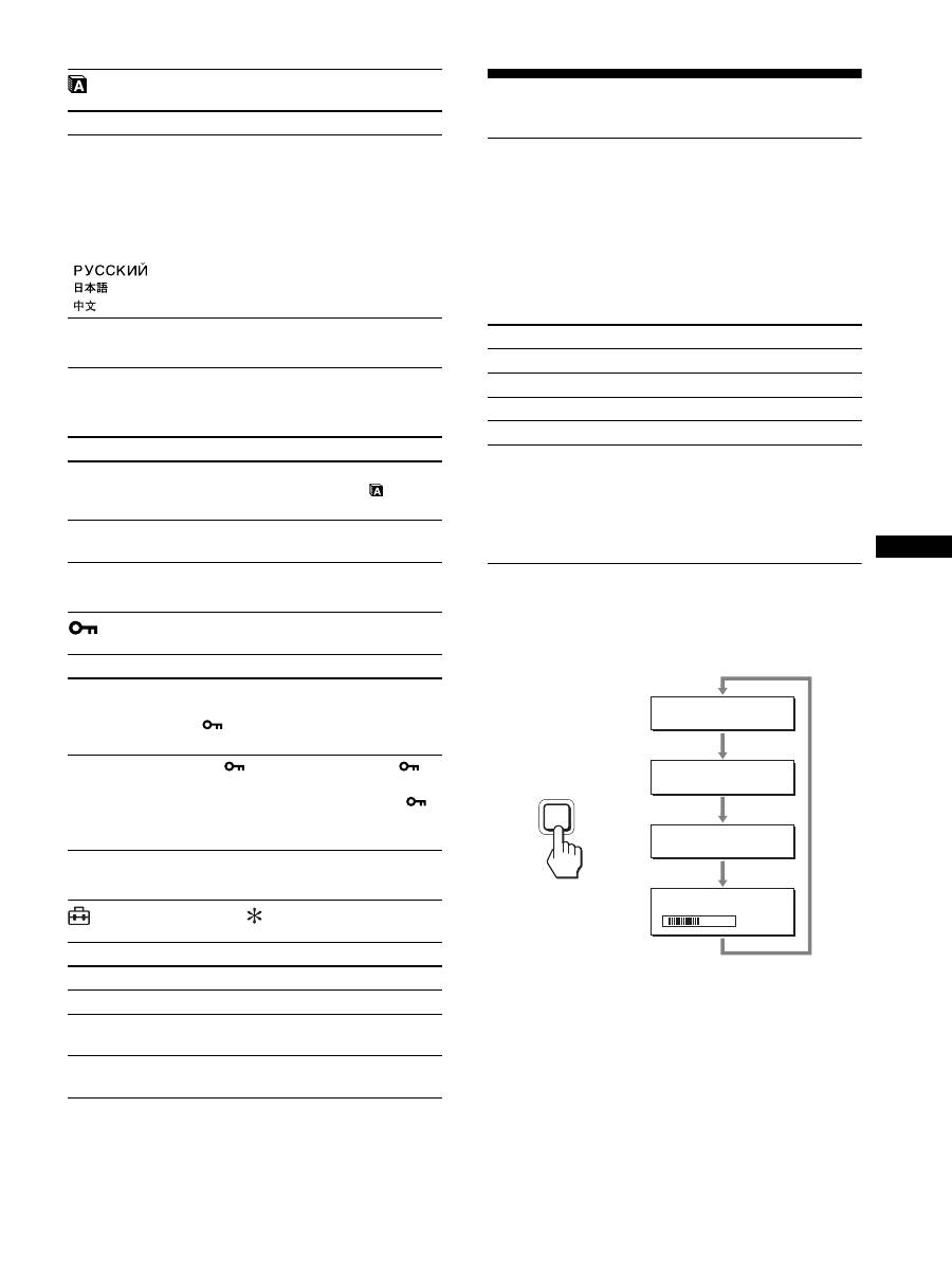
17
GB
LANGUAGE menu
0
RESET menu (reset to the
default setting)
MENU LOCK menu
OPTION menu
Technical Features
Power saving function
This display meets the power saving guidelines set by VESA,
E
NERGY
S
TAR, and NUTEK. If the display is connected to a
computer or video graphics board that is DPMS (Display Power
Management Standard) for Analog input / DMPM (DVI Digital
Monitor Power Management) for Digital input compliant, the
display will automatically reduce power consumption as shown
below.
1)
When your computer enters the “active off” mode, the input signal is
cut and NO INPUT SIGNAL appears on the screen. After 5 seconds,
the display enters the power saving mode.
“deep sleep” is the power saving mode defined by the Environmental
Protection Agency.
Reducing the power consumption
(ECO mode)
If you press the ECO button on the front of the display repeatedly,
you can select the screen brightness.
Each mode appears on the screen and the screen brightness is
reduced according to the mode. The menu automatically
disappears after about 5 seconds.
Screen brightness and power consumption are reduced as the
mode changes from HIGH to MIDDLE to LOW.
The default setting of the screen brightness is set to HIGH.
Items
Press the
m
/
M
buttons
ENGLISH
FRANÇAIS
DEUTSCH
ESPAÑOL
ITALIANO
NEDERLANDS
SVENSKA
French
German
Spanish
Italian
Dutch
Swedish
Russian
Japanese
Chinese
Items
Features
OK
To reset all the adjustment data to the
default setting except for the
(LANGUAGE) menu setting.
CANCEL
To cancel resetting and return to the
menu screen.
Items
Features
ON
Only the
1
(power) switch will operate.
If you attempt any other operation, the
(MENU LOCK) icon appears on the
screen.
OFF
Set
(MENU LOCK) to off. If
(MENU LOCK) has been set to ON,
when you press the MENU button,
(MENU LOCK) is automatically
selected.
Items
MENU ROTATION
Options
Features
LANDSCAPE
Displays the screen in the landscape
position.
PORTRAIT
Displays the screen in the portrait
position.
Power mode
1
(power) indicator
normal operation
green
active off
1)
(deep sleep)
orange
power off
red
main power off
off
E C O
L OW
:
E C O
AU TO
:
E C O
H I G H
:
E C O
M I D D L E
:
5 0
ECO
,

18
Automatic brightness adjustment
function (light sensor)
This display is provided with a feature to automatically adjust the
screen brightness according to the brightness of the surroundings.
The brightness of the screen is set to the most appropriate level by
setting the ECO mode to AUTO with the ECO button on the front
of the display, or in the PICTURE ADJUST menu. The default
setting of the brightness of the screen is set to HIGH. Also, when
you set the ECO mode to “AUTO” with the ECO button on the
front of the display, the adjustment bar is also displayed. You can
adjust the bar with the
m
/
M
buttons. Screen brightness changes
according to the level you set.
Automatic picture quality
adjustment function (analog RGB
signal only)
When the display receives an input signal, it
automatically adjusts the picture’s position and
sharpness (phase/pitch), and ensures that a clear
picture appears on the screen.
The factory preset mode
When the display receives an input signal, it automatically
matches the signal to one of the factory preset modes stored in the
display’s memory to provide a high quality picture at the center of
the screen. If the input signal matches the factory preset mode, the
picture appears on the screen automatically with the appropriate
default adjustments.
If input signals do not match one of the factory
preset modes
When the display receives an input signal that does not match one
of the factory preset modes, the automatic picture quality
adjustment function of this display is activated to ensure that a
clear picture always appears on the screen (within the following
display frequency ranges):
Horizontal frequency: 28–92 kHz (analog RGB)
28–75 kHz (digital RGB)
Vertical frequency:
48–85 Hz (analog RGB)
60 Hz (digital RGB)
Consequently, the first time the display receives input signals that
do not match one of the factory preset modes, the display may
take a longer time than normal to display the picture on the screen.
This adjustment data is automatically stored in memory so that,
the display will function in the same way as when the display
receives the signals that match one of the factory preset modes
next time.
If you adjust the phase, pitch, and picture position
manually
For some input signals, the automatic picture quality adjustment
function of this display may not completely adjust the picture
position, phase, and pitch. In this case, you can set these
adjustments manually (page 16). If you set these adjustments
manually, they are stored in memory as user modes and
automatically recalled whenever the display receives the same
input signals.
Note
While the automatic picture quality adjustment function is activated, only
the
1
(power) switch will operate.
KVM function (Keyboard-Video-
Mouse function)
You can use up to two computers connecting between the USB
mouse and USB keyboard switching INPUT/OK button (page 8)
back and forth.
About USB port
• We recommend that you connect the USB mouse and the USB
keyboard to the USB port of the display. If you connect the
devices other than the above, the display might fail to operate
properly. Or, the devices that are compatible with Bluetooth
might fail to operate properly.
• The USB port on the display is compatible with USB Full-
Speed (Max 12 Mbps).
Notes
• Even when you press INPUT/OK button, the computers may not be
able to switch back and forth promptly.
• Install the latest USB driver to use the USB devices. The older USB
driver may not operate properly.
• When using a USB hub, set the input signals to the AUTO OFF with
INPUT SENSING menu.
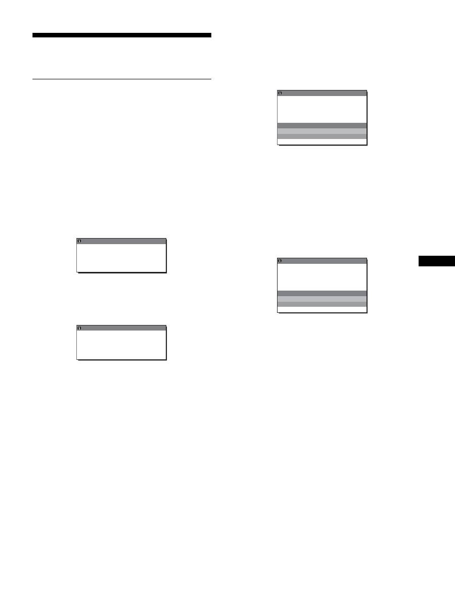
19
GB
Troubleshooting
Before contacting technical support, refer to this section.
On-screen messages
If there is something wrong with the input signal, one of the
following messages appears on the screen. To solve the problem,
see “Trouble symptoms and remedies” on page 20.
If “OUT OF RANGE” appears on the screen
This indicates the input signal is not supported by the display’s
specifications. Check the following items.
For more information about on-screen messages, see “Trouble
symptoms and remedies” on page 20.
If “xxx.x kHz/xxx Hz” is displayed
This indicates either the horizontal or vertical frequency is not
supported by the display’s specifications.
The figures indicate the horizontal and vertical frequencies of
the current input signal.
If “RESOLUTION > 1600
×
1200” is displayed
This indicates that the resolution is not supported by the
display’s specifications (1600
×
1200 or less).
If “NO INPUT SIGNAL” appears on the screen
This indicates that no signal is being input via the currently
selected connector.
When INPUT SENSING (page 16) is set to ON, the display finds
another input signal and changes the input automatically.
When input signals cannot be found,
“GO TO POWER SAVE”
message appears. About 5 seconds later, the power saving
mode starts.
If “CABLE DISCONNECTED” appears on the
screen
This indicates that the video signal cable has been disconnected
from the currently selected connector.
When INPUT SENSING (page 16) is set to ON, the display finds
another input signal and changes the input automatically.
When input signals cannot be found,
“GO TO POWER SAVE”
message appears. About 45 seconds later, the power saving
mode starts.
OUT OF RANGE
I NPUT 1 DV I - D
x x x . x k H z /
x x x H z
I NFORMA T I ON
:
Example
OUT OF RANGE
RESOL UT I ON >
6
1
0 0 X 1
0
0
2
I NFORMA T I ON
I NPUT 1 : DV I - D
Example
I NFORMA T I ON
NO
I NPUT S I GNA L
GO TO POWER SAVE
I NPUT 1 DV I - D
:
Example
CAB L E D I SCONNECT ED
I NFORMA T I ON
I NPUT 1 DV I - D
:
GO TO POWER SAVE
Example

20
Trouble symptoms and remedies
If a problem occurs as a result of a connected computer or other equipment, refer to the connected computer/equipment’s instruction manual.
Symptom
Check these items
No picture
If the
1
(power) indicator is not lit,
or if the
1
(power) indicator will not
light up when the
1
(power) switch
is pressed:
• Check that the power cord is properly connected.
• Check that the MAIN POWER switch on the display is turned on (page 10).
If the
1
(power) indicator turns on
in red:
• Check that the
1
(power) switch is on.
If “CABLE DISCONNECTED”
appears on the screen:
• Check that the video signal cable is properly connected and all plugs are firmly seated in
their sockets (page 7).
• Check that the video input connector’s pins are not bent or pushed in.
• Check that the input select setting is correct (page 12).
• A non-supplied video signal cable is connected. If you connect a non-supplied video
signal cable, CABLE DISCONNECTED may appear on the screen. This is not a
malfunction.
“NO INPUT SIGNAL” warning
message appears on the screen, or
1
(power) indicator turns orange:
• Check that the video signal cable is properly connected and all plugs are firmly seated in
their sockets (page 7).
• Check that the video input connector’s pins are not bent or pushed in.
• Check that the input select setting is correct (page 12).
x
Problems caused by a computer or other equipment connected, and not
caused by the display
• The computer is in the power saving mode. Try pressing any key on the keyboard or
moving the mouse.
• Check that your graphics board is installed properly.
• Check that the computer’s power is on.
• Restart the computer.
If “OUT OF RANGE” appears on
the screen (page 19):
x
Problems caused by a computer or other equipment connected, and not
caused by the display
• Check that the video frequency range is within that specified for the display. If you
replaced an old display with this display, reconnect the old display and adjust the
computer’s graphics board within the following ranges:
Horizontal: 28 – 92 kHz (analog RGB), 28 – 75 kHz (digital RGB)
Vertical: 48 – 85 Hz (analog RGB), 60 Hz (digital RGB)
Resolution: 1600
×
1200 or less
If using Windows:
• If you replaced an old display with this display, reconnect the old display and do the
following. Select “SONY” from the “Manufacturers” list and select the desired model
name from the “Models” list in the Windows device selection screen. If the model name of
this display does not appear in the “Models” list, try “Plug & Play.”
If using a Macintosh system:
• When connecting a Macintosh computer, use an adapter (not supplied) if necessary.
Connect that adapter to the computer before connecting the video signal cable.
Picture flickers, bounces,
oscillates, or is scrambled
• Adjust the pitch and phase (analog RGB signal only) (page 16).
• Try plugging the display into a different AC outlet, preferably on a different circuit.
x
Problems caused by a computer or other equipment connected, and not
caused by the display
• Check your graphics board manual for the proper display setting.
• Confirm that the graphics mode (VESA, Macintosh 19" Color, etc.) and the frequency of
the input signal are supported by this display. Even if the frequency is within the proper
range, some graphics boards may have a sync pulse that is too narrow for the display to
sync correctly.
• This display does not process interlace signals. Set for progressive signals.
• Adjust the computer’s refresh rate (vertical frequency) to obtain the best possible picture.
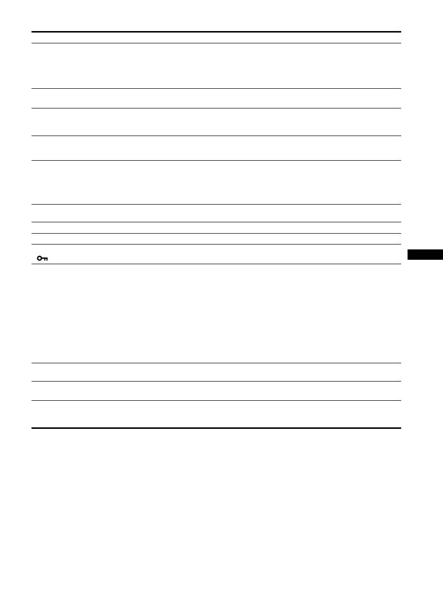
21
GB
Picture is fuzzy
• Adjust the brightness and contrast (page 15).
• Adjust the pitch and phase (analog RGB signal only) (page 16).
x
Problems caused by a computer or other equipment connected, and not
caused by the display
• Set the resolution to 1600
×
1200 on your computer.
Picture is ghosting
• Eliminate the use of video cable extensions and/or video switch boxes.
• Check that all plugs are firmly seated in their sockets.
Picture is not centered or sized
properly (analog RGB signal only)
• Adjust the pitch and phase (page 16).
• Adjust the picture position (page 16). Note that some video modes do not fill the screen to
the edges.
Picture is too small
x
Problems caused by a computer or other equipment connected, and not
caused by the display
• Set the resolution to 1600
×
1200 on your computer.
Picture is dark
• Adjust the backlight (page 15).
• Adjust the brightness (page 15).
• Adjust the gamma using GAMMA menu (page 15).
• It takes a few minutes for the display to become bright after turning on the display.
• The screen might turn darker, depends on ECO mode you selected.
Wavy or elliptical pattern (moire)
is visible
• Adjust the pitch and phase (analog RGB signal only) (page 16).
Color is not uniform
• Adjust the pitch and phase (analog RGB signal only) (page 16).
White does not look white
• Adjust the color temperature (page 15).
Display buttons do not operate
(
appears on the screen)
• If MENU LOCK is set to ON, set it to OFF (page 17).
The device connecting through
the USB cable fails to operate
• Check the USB cable (supplied) is connected properly (page 8).
• Press the MAIN POWER switch and the
1
(power) indicator to turn on the display.
x
Problems caused by your computer or other connected device
• Check if your device has been turned on.
• Reinstall the updated USB driver. For more information, contact the manufacture of your
product.
• If you fail to operate your computer with the keyboard or mouse attached to the display,
connect the keyboard or mouse to your computer directly. After restarting your computer,
reset the USB connection. After having completed this process, connect the keyboard or
mouse back to the display. When the display is connected to a computer, keyboard, or
mouse via the USB port, you might not be able to operate your computer with them as you
restart the computer.
The display turns off after a while
x
Problems caused by the connected computer or other equipment
• Set the computer’s power saving setting to off.
Resolution displayed on the menu
screen is incorrect
• Depending on the graphics board setting, the resolution displayed on the menu screen may
not coincide with the one set on the computer.
After turning off the main power,
the
1
(power) indicator stays
bright for a while
• When the main power is on but the
1
(power) switch is not pressed, or when the display is
in the power saving mode, if you turn the MAIN POWER switch off, the
1
(power)
indicator may not turn off right away. This is not a malfunction.
Symptom
Check these items
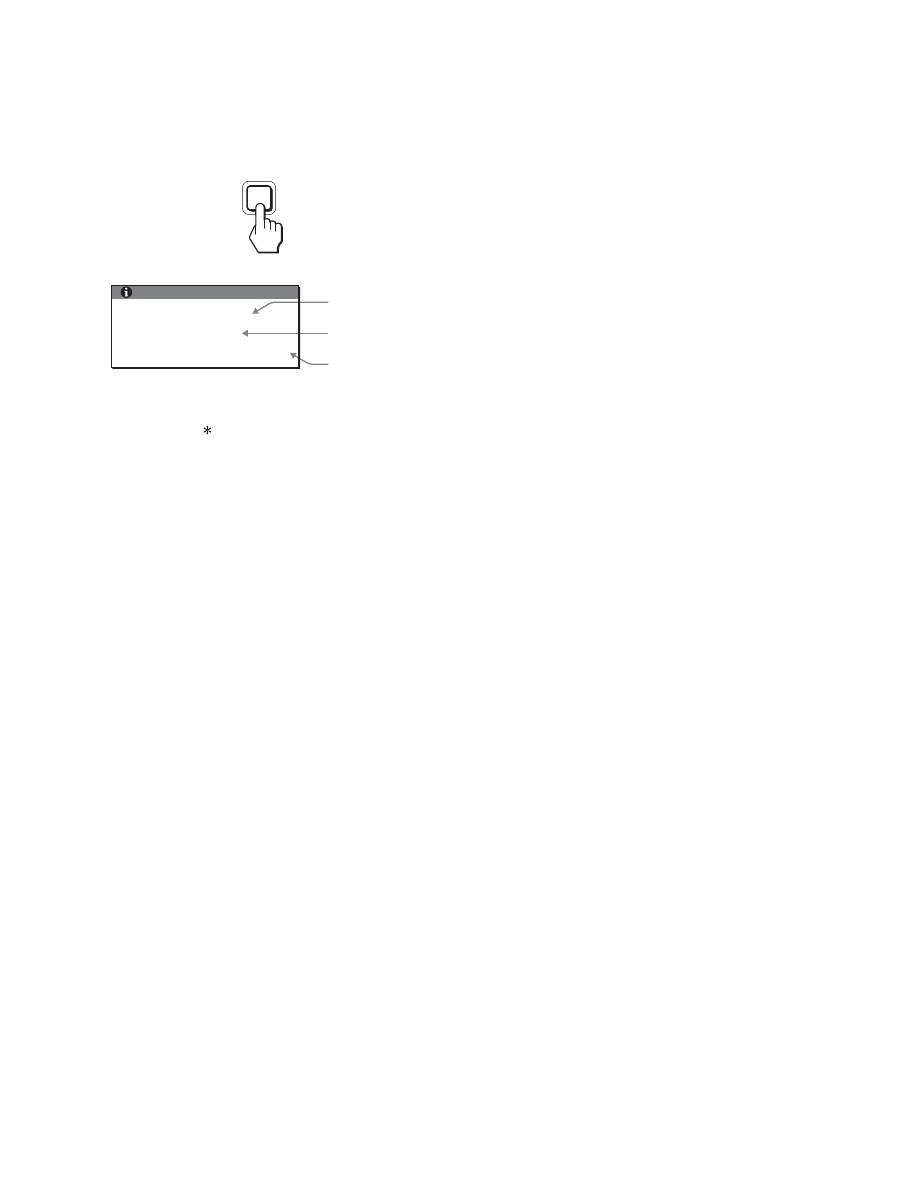
22
Displaying this display’s information
While the display is receiving a video signal, press and
hold the MENU button for more than 5 seconds until the
information box appears.
Press the MENU button again to make the box disappear.
Although the safety standard registered model name of this
display is SDM-S205 , the name of SDM-S205F/S205K is used
on sale.
If any problem persists, call your authorized Sony dealer and give
the following information:
• Model name
• Serial number
• Detailed description of the problem
• Date of purchase
• Name and specifications of your computer and graphics board
• Type of input signals (analog RGB/digital RGB)
MENU
Example
Model name
Serial number
Week and year
of manufacture
INFORMATION
MODEL : SDM-S205F
SER. NO : 1234567
MANUFACTURED : 2005-52
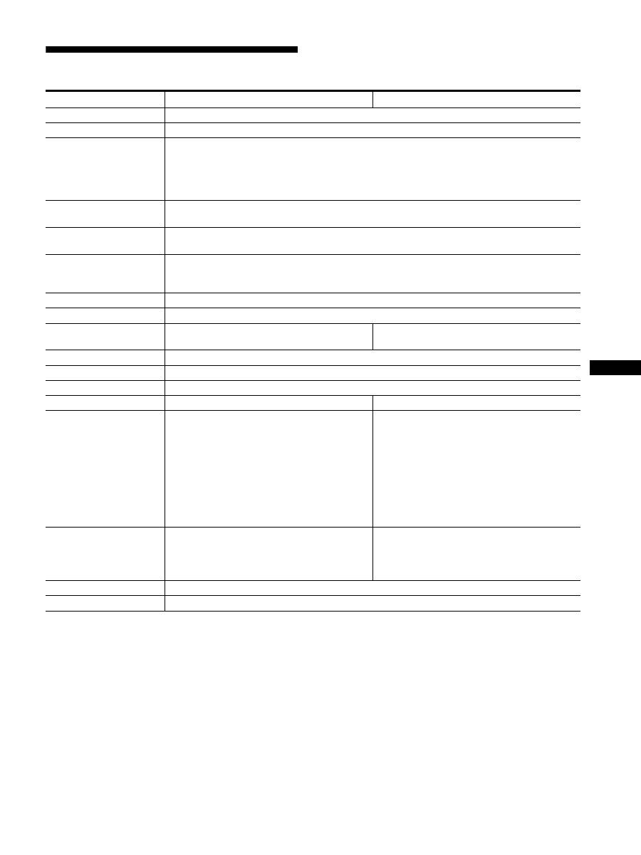
23
GB
Specifications
1)
Recommended horizontal and vertical timing condition
• Horizontal sync width duty should be more than 4.8% of total
horizontal time or 0.8 µs, whichever is larger.
• Horizontal blanking width should be more than 2.5 µsec.
• Vertical blanking width should be more than 450 µsec.
Design and specifications are subject to change without notice.
Model name
SDM-S205F
SDM-S205K
LCD panel
Panel type: a-Si TFT Active Matrix
Picture size: inch
20.1
Input signal format
RGB operating frequency
1)
Horizontal: 28 – 92 kHz (analog RGB)
28 – 75 kHz (digital RGB)
Vertical: 48 – 85 Hz (analog RGB)
60 Hz (digital RGB)
Resolution
Horizontal: Max.1600 dots
Vertical: Max.1200 lines
Type of input signal
(Digital/Analog)
Digital
×
1/Analog
×
1
Input signal levels
Analog RGB video signal 0.7 Vp-p, 75
Ω
, positive
SYNC signal TTL level, 2.2 k
Ω
, positive or negative
Digital RGB (DVI) signal TMDS (single link)
Audio input
Stereo minijack, 0.5 Vrms
Audio output
Stereo minijack
USB port
–
USB Full-Speed (Max12 Mbps)
A Port
×
4, B Port
× 2
Power requirements
100 – 240 V, 50 – 60 Hz, Max. 1.2 A
Power consumption
Max. 55 W
Operating temperature
5 – 35 °C
Type of the stand
Height adjust
Pivot
Dimensions (width/height/
depth)
Approx. 441.5
×
410.5 – 520.5
×
277.5 mm
(17
3
/
8
×
16
1
/
4
– 20
1
/
2
×
11 inches)
(with stand)
Approx. 441.5
×
356.5
×
74 mm
(17
3
/
8
×
14
1
/
8
×
2
7
/
8
inches)
(without stand)
Approx. 441.5
×
421 – 551
×
277.5 mm
(17
3
/
8
×
16
5
/
8
– 21
3
/
4
×
11 inches)
(with stand(normal condition))
Approx. 356.5
×
470.5 – 600.5
×
277.5 mm
(14
1
/
8
×
18
5
/
8
– 23
3
/
4
×
11 inches)
(with stand (pivoted condition))
Approx. 441.5
×
356.5
×
74 mm
(17
3
/
8
×
14
1
/
8
×
2
7
/
8
inches)
(without stand)
Mass
Approx. 9.6 kg (21 lb 2
3
/
8
oz)
(with stand)
Approx. 6.0 kg (13 lb 3
3
/
8
oz)
(without stand)
Approx. 9.9 kg (21 lb 12
3
/
16
oz)
(with stand)
Approx. 6.1 kg (13 lb 6
3
/
5
oz)
(without stand)
Plug & Play
DDC2B
Accessories
See page 6.

i
TCO’99 Eco-document (for the black
model)
x
Congratulations!
You have just purchased a TCO’99 approved and labelled product! Your
choice has provided you with a product developed for professional use.
Your purchase has also contributed to reducing the burden on the
environment and also to the further development of environmentally
adapted electronics products.
x
Why do we have environmentally labelled com-
puters?
In many countries, environmental labelling has become an established
method for encouraging the adaptation of goods and services to the
environment. The main problem, as far as computers and other electronics
equipment are concerned, is that environmentally harmful substances are
used both in the products and during their manufacture. Since it is not so
far possible to satisfactorily recycle the majority of electronics equipment,
most of these potentially damaging substances sooner or later enter nature.
There are also other characteristics of a computer, such as energy
consumption levels, that are important from the viewpoints of both the
work (internal) and natural (external) environments. Since all methods of
electricity generation have a negative effect on the environment (e.g.
acidic and climate-influencing emissions, radioactive waste), it is vital to
save energy. Electronics equipment in offices is often left running
continuously and thereby consumes a lot of energy.
x
What does labelling involve?
This product meets the requirements for the TCO’99 scheme which
provides for international and environmental labelling of personal
computers. The labelling scheme was developed as a joint effort by the
TCO (The Swedish Confederation of Professional Employees), Svenska
Naturskyddsforeningen (The Swedish Society for Nature Conservation)
and Statens Energimyndighet (The Swedish National Energy
Administration).
Approval requirements cover a wide range of issues: environment,
ergonomics, usability, emission of electric and magnetic fields, energy
consumption and electrical and fire safety.
The environmental demands impose restrictions on the presence and use
of heavy metals, brominated and chlorinated flame retardants, CFCs
(freons) and chlorinated solvents, among other things. The product must
be prepared for recycling and the manufacturer is obliged to have an
environmental policy which must be adhered to in each country where the
company implements its operational policy.
The energy requirements include a demand that the computer and/or
display, after a certain period of inactivity, shall reduce its power
consumption to a lower level in one or more stages. The length of time to
reactivate the computer shall be reasonable for the user.
Labelled products must meet strict environmental demands, for example,
in respect of the reduction of electric and magnetic fields, physical and
visual ergonomics and good usability.
Below you will find a brief summary of the environmental requirements
met by this product. The complete environmental criteria document may
be ordered from:
TCO Development
SE-114 94 Stockholm, Sweden
Fax: +46 8 782 92 07
Email (Internet): development@tco.se
Current information regarding TCO’99 approved and labelled
products may also be obtained via the Internet, using the address:
http://www.tco-info.com/
x
Environmental requirements
Flame retardants
Flame retardants are present in printed circuit boards, cables, wires,
casings and housings. Their purpose is to prevent, or at least to delay the
spread of fire. Up to 30% of the plastic in a computer casing can consist
of flame retardant substances. Most flame retardants contain bromine or
chloride, and those flame retardants are chemically related to another
group of environmental toxins, PCBs. Both the flame retardants
containing bromine or chloride and the PCBs are suspected of giving rise
to severe health effects, including reproductive damage in fish-eating
birds and mammals, due to the bio-accumulative
*
processes. Flame
retardants have been found in human blood and researchers fear that
disturbances in foetus development may occur.
The relevant TCO’99 demand requires that plastic components weighing
more than 25 grams must not contain flame retardants with organically
bound bromine or chlorine. Flame retardants are allowed in the printed
circuit boards since no substitutes are available.
Cadmium
**
Cadmium is present in rechargeable batteries and in the colour-generating
layers of certain computer displays. Cadmium damages the nervous
system and is toxic in high doses. The relevant TCO’99 requirement states
that batteries, the colour-generating layers of display screens and the
electrical or electronics components must not contain any cadmium.
Mercury
**
Mercury is sometimes found in batteries, relays and switches. It damages
the nervous system and is toxic in high doses. The relevant TCO’99
requirement states that batteries may not contain any mercury. It also
demands that mercury is not present in any of the electrical or electronics
components associated with the labelled unit.
CFCs (freons)
The relevant TCO’99 requirement states that neither CFCs nor HCFCs
may be used during the manufacture and assembly of the product. CFCs
(freons) are sometimes used for washing printed circuit boards. CFCs
break down ozone and thereby damage the ozone layer in the stratosphere,
causing increased reception on earth of ultraviolet light with e.g. increased
risks of skin cancer (malignant melanoma) as a consequence.
Lead
**
Lead can be found in picture tubes, display screens, solders and
capacitors. Lead damages the nervous system and in higher doses, causes
lead poisoning. The relevant TCO’99 requirement permits the inclusion of
lead since no replacement has yet been developed.
*
Bio-accumulative is defined as substances which accumulate within
living organisms.
** Lead, Cadmium and Mercury are heavy metals which are Bio-
accumulative.

ii
TCO’03 Eco-document (for the silver
model)
x
Congratulations!
The display you have just purchased carries the TCO’03
Displays label. This means that your display is designed,
manufactured and tested according to some of the strictest
quality and environmental requirements in the world. This
makes for a high performance product, designed with the
user in focus that also minimizes the impact on our natural
environment.
x
Ergonomics
• Good visual ergonomics and image quality in order to
improve the working environment for the user and to
reduce sight and strain problems. Important parameters
are luminance, contrast, resolution, reflectance, colour
rendition and image stability.
x
Energy
• Energy-saving mode after a certain time – beneficial
both for the user and the environment
• Electrical safety
x
Emissions
• Electromagnetic fields
• Noise emissions
x
Ecology
• The product must be prepared for recycling and the
manufacturer must have a certified environmental
management system such as EMAS or ISO 14 001
• Restrictions on
- chlorinated and brominated flame retardants and
polymers
- heavy metals such as cadmium, mercury and lead.
The requirements included in this label have been
developed by TCO Development in co-operation with
scientists, experts, users as well as manufacturers all over
the world. Since the end of the 1980s TCO has been
involved in influencing the development of IT equipment
in a more user-friendly direction. Our labelling system
started with displays in 1992 and is now requested by users
and IT-manufacturers all over the world.
For more information, please visit
www.tcodevelopment.com
Recycling Information
x
Customer in Europe
The collection and recycling of this product has been planned
according to your country’s relevant legislation. To ensure that
this product will be collected and recycled in way that minimizes
the impact on the environment, please do the following:
1. If you purchased this product for private use, contact your
municipality or the waste collection system and bring the
product to this collection point / have the product be picked up
by the waste collection system. Alternatively, your retailer
might take back this if you purchase new equivalent equipment;
please check with your retailer whether he will take back this
product before bringing it. For information on your country’s
recycling arrangements, please contact the Sony representation
in your country (contact details at: www.sony-europe.com).
Further details on specific recycling systems can be found at the
following addresses:
- Belgium: www.recupel.be
- Netherlands: www.nvmp.nl (consumer electronics)
www.ictmilieu.nl (IT equipment)
- Norway: www.elretur.no
- Sweden: www.el-kretsen.se
- Switzerland: www.swico.ch
2. If you use this product professionally, check the product’s
delivery contract for take back / recycling arrangements and
follow the procedures described therein. Alternatively, follow
the procedures described under point 1.
x
Customer in USA
We Sony as a member of EIA recommends to visit URL below
http://www.eiae.org/
x
Customer in Asia
http://www.sony.co.jp/SonyInfo/Environment/recycle/3R.html

2-649-019-
04
(1)
© 2005 Sony Corporation
TFT LCD Color Computer Display
SDM-S205
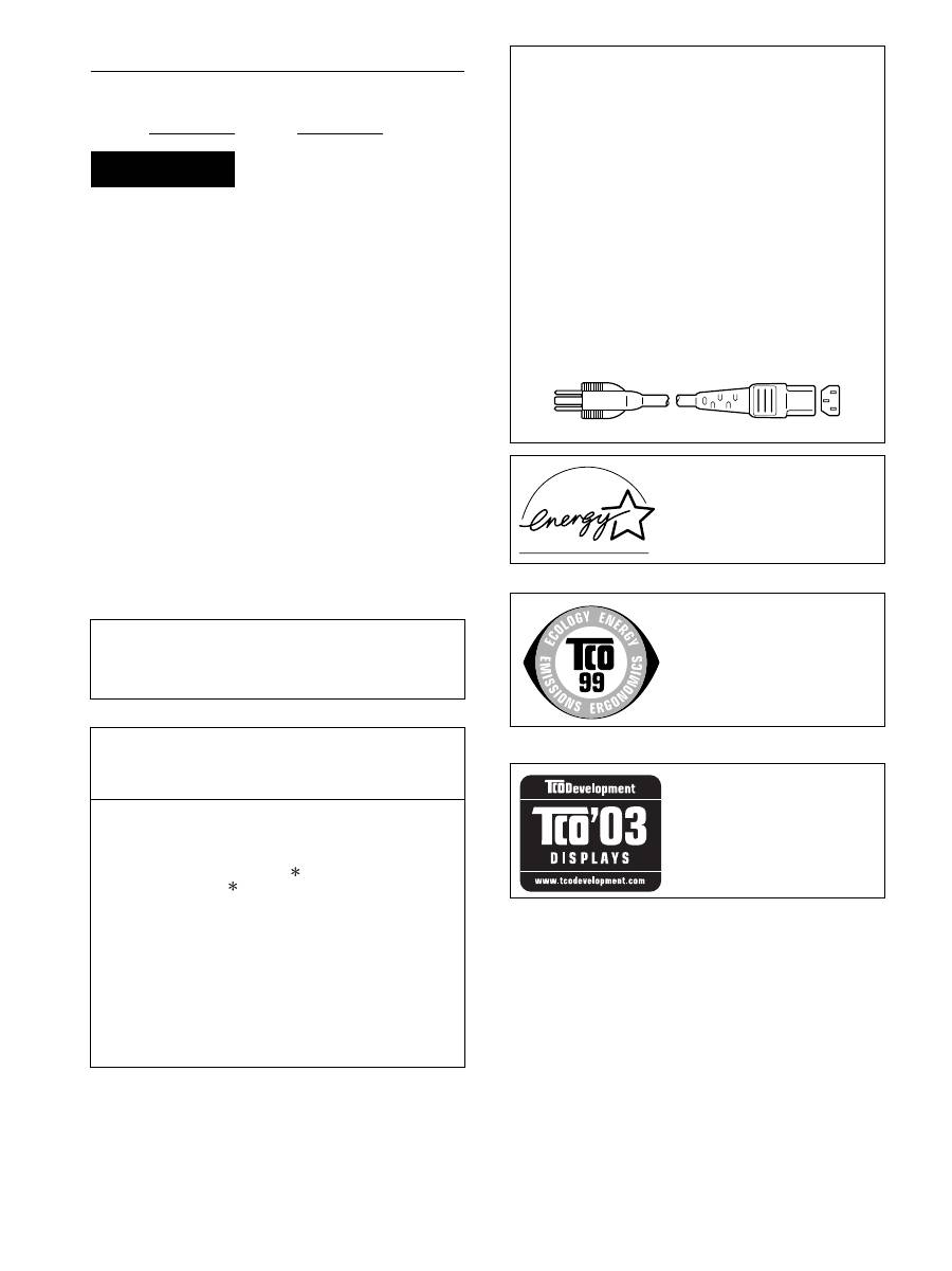
2
Owner’s Record
The model and serial numbers are located at the rear of the unit.
Record these numbers in the spaces provided below. Refer to them
whenever you call upon your dealer regarding this product.
Model No. Serial No.
To reduce the risk of fire or electric shock, do not
expose this apparatus to rain or moisture.
Dangerously high voltages are present inside the
unit. Do not open the cabinet. Refer servicing to
qualified personnel only.
FCC Notice
This equipment has been tested and found to comply with the limits
for a Class B digital device, pursuant to Part 15 of the FCC Rules.
These limits are designed to provide reasonable protection against
harmful interference in a residential installation. This equipment
generates, uses, and can radiate radio frequency energy and, if not
installed and used in accordance with the instructions, may cause
harmful interference to radio communications. However, there is no
guarantee that interference will not occur in a particular installation.
If this equipment does cause harmful interference to radio or
television reception, which can be determined by turning the
equipment off and on, the user is encouraged to try to correct the
interference by one or more of the following measures:
– Reorient or relocate the receiving antenna.
– Increase the separation between the equipment and receiver.
– Connect the equipment into an outlet on a circuit different from
that to which the receiver is connected.
– Consult the dealer or an experienced radio/TV technician for help.
You are cautioned that any changes or modifications not expressly
approved in this manual could void your authority to operate this
equipment.
N’oubliez pas de vérifier le carton fourni avec votre écran.
L’étiquette d’identification du modèle de votre écran figure à
l’arrière de celui-ci.
(for the black model)
(for the silver model)
WARNING
IMPORTANTE
Para prevenir cualquier mal funcionamiento y evitar daños, por
favor, lea detalladamente este manual de instrucciones antes
de conectar y operar este equipo.
If you have any questions about this product, you may call;
Sony Customer Information Services Center 1-800-222-7669
or http://www.sony.com/
Declaration of Conformity
Trade Name
: SONY
Model
: SDM-S205
Note
: means any number or alphanumeric
character.
Responsible Party
: Sony Electronics Inc.
Address
: 16530 Via Esprillo, San Diego, CA
92127 U.S.A.
Telephone Number : 858-942-2230
This device complies with part 15 of the FCC rules. Operation is
subject to the following two conditions: (1) This device may not
cause harmful interference, and (2) this device must accept any
interference received, including interference that may cause
undesired operation.
NOTICE
This notice is applicable for USA/Canada only.
If shipped to USA/Canada, install only a UL LISTED/CSA
LABELLED power supply cord meeting the following
specifications:
SPECIFICATIONS
Plug Type
Nema-Plug 5-15p
Cord
Type SVT or SJT, minimum 3
×
18 AWG
Length
Maximum 15 feet
Rating
Minimum 7 A, 125 V
NOTICE
Cette notice s’applique aux Etats-Unis et au Canada
uniquement.
Si cet appareil est exporté aux Etats-Unis ou au Canada, utiliser
le cordon d’alimentation portant la mention UL LISTED/CSA
LABELLED et remplissant les conditions suivantes:
SPECIFICATIONS
Type de fiche
Fiche Nema 5-15 broches
Cordon
Type SVT ou SJT, minimum 3
×
18 AWG
Longueur
Maximum 15 pieds
Tension
Minimum 7 A, 125 V
As an
E
NERGY
S
TAR Partner, Sony
Corporation has determined that this
product meets the
E
NERGY
S
TAR
guidelines for energy efficiency.
This monitor complies with the
TCO’99 guidelines.
This monitor complies with the
TCO’03 guidelines.

Table des matières
• Macintosh est une marque commerciale
sous licence d’Apple Computer, Inc.,
déposée aux Etats-Unis et dans d’autres
pays.
• Windows
®
est une marque commerciale
déposée de Microsoft Corporation aux
Etats-Unis et dans d’autres pays.
• IBM PC/AT et VGA sont des marques
commerciales déposées d’IBM
Corporation aux Etats-Unis.
• VESA et DDC
™
sont des marques
commerciales de Video Electronics
Standards Association.
•
E
NERGY
S
TAR est une marque
déposée aux Etats-Unis.
• Adobe et Acrobat sont des marques
commerciales de Adobe Systems
Incorporated.
• Tous les autres noms de produit
mentionnés dans le présent mode
d’emploi peuvent être des marques
commerciales ou des marques
commerciales déposées de leurs
entreprises respectives.
• De plus, les symboles
«
™
»
et
«
®
»
ne
sont pas systématiquement mentionnés
dans ce mode d’emploi.
3
FR
http://www.sony.net/
3
Précautions. . . . . . . . . . . . . . . . . . . . . . . . . . . . . . . . . . . . . . . . . . . . 4
Vérification du nom du modèle de l’écran. . . . . . . . . . . . . . . . . . . . . 5
Identification des composants et des commandes . . . . . . . . . . . . . . 5
Installation . . . . . . . . . . . . . . . . . . . . . . . . . . . . . . . . . . . . .6
Étape 1 :
Assemblez le support . . . . . . . . . . . . . . . . . . . . . . . . . . . . 6
Étape 2 :
Raccordez les câbles de signal vidéo. . . . . . . . . . . . . . . . 7
Étape 3 :
Raccordez la souris USB ou le clavier USB ou d’autres
périphériques (modèles équipés de ports USB uniquement) . 8
Étape 4 :
Raccordez les cordons audio . . . . . . . . . . . . . . . . . . . . . . 9
Étape 5 :
Branchez le cordon d’alimentation . . . . . . . . . . . . . . . . . . 9
Étape 6 :
Fixez les cordons et refermez le couvercle des
connecteurs . . . . . . . . . . . . . . . . . . . . . . . . . . . . . . . . . . . 9
Étape 7 :
Mettez l’écran et l’ordinateur sous tension . . . . . . . . . . . 10
Étape 8 :
Réglez l’inclinaison et la hauteur . . . . . . . . . . . . . . . . . . 11
Basculement de votre image entre portrait/paysage
(Uniquement pour les modèles auquel un support pivotant est fixé). . . . . 12
Sélection du signal d’entrée (INPUT1/INPUT2) . . . . . . . . . . . . . . . 12
Personnalisation de votre écran . . . . . . . . . . . . . . . . . .13
Pilotage par menu. . . . . . . . . . . . . . . . . . . . . . . . . . . . . . . . . . . . . . 13
Liste des éléments de menu. . . . . . . . . . . . . . . . . . . . . . . . . . . . . . 14
Menu RÉGLAGE IMAGE . . . . . . . . . . . . . . . . . . . . . . . . . . . . . 15
Menu ÉCRAN (signal RVB analogique uniquement) . . . . . . . . 15
Menu ZOOM . . . . . . . . . . . . . . . . . . . . . . . . . . . . . . . . . . . . . . 16
Menu POSITION MENU . . . . . . . . . . . . . . . . . . . . . . . . . . . . . 16
Menu DÉTECTE ENTRÉE. . . . . . . . . . . . . . . . . . . . . . . . . . . . 16
Menu LANGUAGE . . . . . . . . . . . . . . . . . . . . . . . . . . . . . . . . . 17
0
Menu RÉINITIALISATIO
(réinitialisation aux valeurs par défaut) . . . . . . . . . . . . . . . . . . 17
Menu VERROU DU MENU . . . . . . . . . . . . . . . . . . . . . . . . . . . 17
Menu OPTION . . . . . . . . . . . . . . . . . . . . . . . . . . . . . . . . . . . . 17
Spécifications techniques. . . . . . . . . . . . . . . . . . . . . . . .17
Fonction d’économie d’énergie . . . . . . . . . . . . . . . . . . . . . . . . . . . . 17
Réduction de la consommation électrique (Mode-ECO) . . . . . . . . 17
Fonction de réglage automatique de la luminosité
(capteur de lumière) . . . . . . . . . . . . . . . . . . . . . . . . . . . . . . . . . . . . 18
Fonction de réglage automatique de la qualité de l’image
(signal RVB analogique uniquement) . . . . . . . . . . . . . . . . . . . . . . . 18
Fonction KVM (Fonction Clavier-Vidéo-Souris) . . . . . . . . . . . . . . . 18
Dépannage . . . . . . . . . . . . . . . . . . . . . . . . . . . . . . . . . . . .19
Messages affichés . . . . . . . . . . . . . . . . . . . . . . . . . . . . . . . . . . . . . 19
Symptômes de défaillances et remèdes. . . . . . . . . . . . . . . . . . . . . 20
Spécifications. . . . . . . . . . . . . . . . . . . . . . . . . . . . . . . . . .23
TCO’99 Eco-document (for the black model) . . . . . . . . . . . . . . . . . . .i
TCO’03 Eco-document (for the silver model) . . . . . . . . . . . . . . . . . . ii
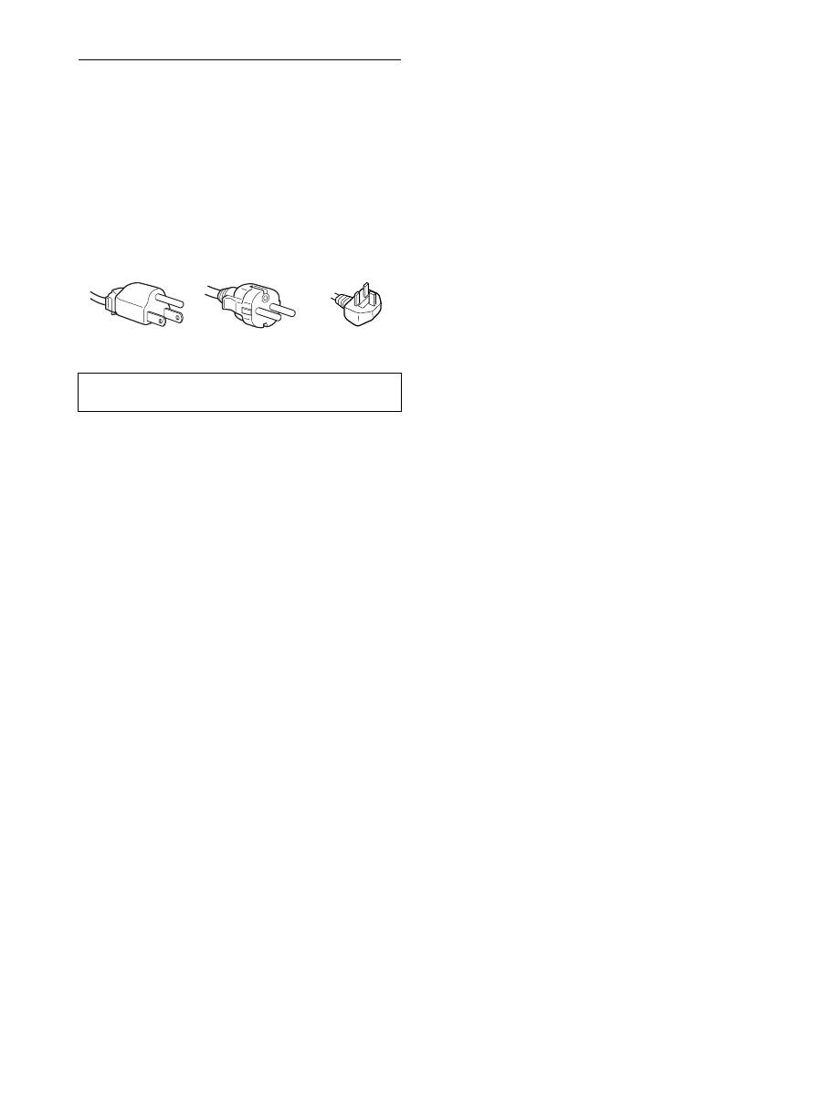
4
Précautions
Avertissement sur les connexions d’alimentation
• Utilisez le cordon d’alimentation fourni. Si vous utilisez un
câble d’alimentation différent, assurez-vous qu’il est
compatible avec la tension secteur locale.
Pour les clients résidant aux Etats-Unis
Si vous n’employez pas le câble approprié, ce moniteur ne sera
pas conforme aux normes FCC obligatoires.
Pour les clients résidant au Royaume-Uni
Si vous utilisez le moniteur au Royaume-Uni, veuillez utiliser
le cordon d’alimentation adapté au Royaume-Uni.
Installation
N’installez pas et ne laissez pas le moniteur :
• A des endroits exposés à des températures extrêmes, par
exemple à proximité d’un radiateur, d’un conduit de chauffage
ou le rayonnement direct du soleil. L’exposition du moniteur à
des températures extrêmes, comme dans l’habitacle d’une
voiture garée en plein soleil ou à proximité d’un conduit de
chauffage, risque d’entraîner des déformations du châssis ou
des dysfonctionnements.
• A des endroits soumis à des vibrations mécaniques ou à des
chocs.
• A proximité d’appareils générant de puissants champs
magnétiques, comme un téléviseur ou d’autres appareils
électroménagers.
• A des endroits soumis à des quantités inhabituelles de poussière,
de saletés ou de sable, par exemple à côté d’une fenêtre ouverte
ou d’une porte donnant sur l’extérieur. En cas d’installation
temporaire à l’extérieur, veillez à prendre les précautions
requises contre la poussière et les saletés en suspension dans l’air.
Faute de quoi des dommages irréparables risquent de se produire.
Les orifices de ventilation, situés sur le dessus à l’arrière de
l’écran, chauffent. Veillez donc à ne pas les toucher.
Manipulation de l’écran LCD
• Ne laissez pas l’écran LCD face au soleil, car vous risquez
sinon de l’endommager. Faites donc attention si vous installez
le moniteur à côté d’une fenêtre.
• N’appuyez pas sur et veillez à ne pas érafler la surface de
l’écran LCD. Ne posez pas d’objets lourds sur l’écran LCD.
Vous risquez sinon d’altérer l’uniformité de l’écran ou de
provoquer un dysfonctionnement de l’écran LCD.
• Lorsque le moniteur est employé dans un environnement froid,
il est possible qu’une image rémanente apparaisse sur l’écran.
Il ne s’agit pas d’un dysfonctionnement. L’écran recouvre sa
condition normale dès que la température est revenue à un
niveau normal.
• Si une image fixe reste affichée pendant une longue durée, il se
peut qu’une image rémanente apparaisse pendant un certain
temps. Cette image rémanente finira par disparaître.
• Le panneau LCD chauffe en cours d’utilisation. Il ne s’agit pas
d’un dysfonctionnement.
Remarque sur l’affichage à cristaux liquides
(LCD - Liquid Crystal Display)
Veuillez noter que l’écran LCD est issu d’une
technologie de haute précision. Toutefois, il est
possible que des points noirs ou des points brillants de
lumière (rouge, bleu ou vert) apparaissent
constamment sur l’écran LCD, ainsi que des bandes de
couleurs irrégulières ou une certaine luminosité. Il ne
s’agit pas d’un dysfonctionnement.
(Pixels actifs : supérieurs à 99,99%)
Entretien
• Débranchez le cordon d’alimentation de la prise secteur avant
de procéder au nettoyage de votre moniteur.
• Nettoyez l’écran LCD avec un chiffon doux. Si vous utilisez un
liquide de nettoyage pour le verre, n’utilisez pas de nettoyant
contenant une solution antistatique ou tout autre additif
similaire, car vous risquez sinon de griffer le revêtement de
l’écran LCD.
• Nettoyez le châssis, le panneau et les commandes à l’aide d’un
chiffon doux légèrement imprégné d’une solution détergente
neutre. N’utilisez aucun type de tampon abrasif, de poudre à
récurer ou de solvant tel que de l’alcool ou de l’essence.
• Ne frottez pas, ne touchez pas et ne tapotez pas la surface de
l’écran avec des objets pointus ou abrasifs comme un stylo à
bille ou un tournevis. Ce type de contact risque de rayer le tube
image.
• Sachez qu’une détérioration des matériaux ou du revêtement de
l’écran LCD risque de se produire si le moniteur est exposé à
des solvants volatils comme des insecticides ou en cas de
contact prolongé avec des objets en caoutchouc ou en vinyle.
Transport
• Débranchez tous les câbles de l’écran. Si vous utilisez un
support à hauteur réglable, réglez-le sur la position la plus
élevée et tenez convenablement l’écran LCD par les deux côtés.
Veillez à ne pas griffer l’écran pendant le transport. Si vous
laissez tomber l’écran, vous risquez de vous blesser ou de
l’endommager.
• Pour transporter ce moniteur en vue de réparations ou de son
expédition, utilisez le carton et les matériaux de
conditionnement originaux.
• Replacez la goupille d’arrêt du support à hauteur réglable pour
immobiliser le support pendant le transport.
Elimination du moniteur
• N’éliminez pas ce moniteur avec les ordures
ménagères.
• Le tube fluorescent utilisé dans ce moniteur contient
du mercure. L’élimination de ce moniteur doit être
effectuée conformément aux réglementations des
administrations compétentes en matière de propreté
publique.
L’appareil doit être installé à proximité d’une prise de courant
aisément accessible.
Exemples de types de fiches
pour 100 à 120 V CA pour 200 à 240 V CA
pour 240 V CA
uniquement

5
FR
FR
Vérification du nom du modèle de
l’écran
Commencez par vérifier le nom du modèle de l’écran.
Le nom du modèle se trouve à l’arrière de l’écran
(Exemple : SDM-S205F).
Vous ne pouvez pas utiliser certaines fonctions et certains menus
avec certains modèles de l’écran.
Identification des composants et
des commandes
Pour plus de détails, reportez-vous aux pages indiquées entre
parenthèses.
L’illustration représente uniquement l’un des modèles
disponibles pour cet écran.
1
Commutateur
1
(alimentation) et
indicateur
1
(alimentation) (pages 10, 17)
Ce commutateur met l’écran sous tension lorsque l’indicateur
1
(alimentation) est rouge. Appuyez de nouveau sur ce
commutateur pour mettre l’écran hors tension.
Si l’indicateur
1
(alimentation) ne s’allume pas, appuyez sur
l’interrupteur MAIN POWER (
8
).
2
Touche MENU (page 13)
Cette touche permet d’activer et de désactiver l’écran de
menu.
3
Touches
m
/
M
(page 13)
Ces touches permettent de sélectionner les options de menu et
d’effectuer des réglages.
4
Touche OK (page 13)
Cette touche active les réglages et les options de menu
sélectionnés à l’aide des touches
m
/
M
(
3
).
INPUT
(page 12)
Ces touches permettent de commuter le signal d’entrée vidéo
entre INPUT1 et INPUT2 lorsque deux ordinateurs sont
raccordés à l’écran. (Disponible uniquement lorsque le menu
est désactivé.)
5
Touche ECO (page 17)
Cette touche permet de réduire la consommation d’énergie.
Lorsque l’écran de menu n’est pas affiché, vous pouvez aussi
régler automatiquement la qualité de l’image du signal
d’entrée en cours en maintenant cette touche enfoncée
pendant plus de 3 secondes (Réglage automatique par touche
unique). (signal RVB analogique uniquement)
6
Capteur de lumière (page 18)
Ce capteur mesure la luminosité autour de l’écran. Veillez à
ne pas recouvrir le capteur avec du papier, etc.
7
Prise de sortie audio (page 9)
Cette prise transmet les signaux audio vers les haut-parleurs
ou vers un autre appareil vidéo.
MENU
INPUT
ECO
OK
7
Avant de l’écran
La marque
indique des informations de spécifications
diverses selon les modèles. Pour plus de détails,
reportez-vous à la section « Spécifications » (page 23).
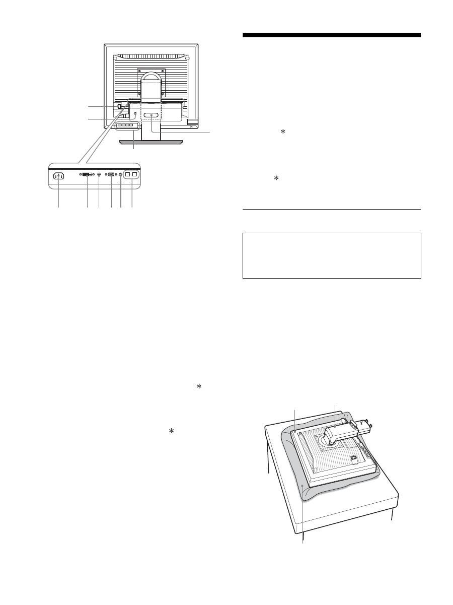
6
Arrière de l’écran
8
Interrupteur MAIN POWER (page 10)
Cet interrupteur active et désactive le commutateur MAIN
POWER de l’écran.
9
Connecteur AC IN (page 9)
Ce connecteur raccorde le cordon d’alimentation (fourni).
0
Connecteur d’entrée DVI-D (RVB numérique)
(page 8)
Ce connecteur transmet des signaux vidéo RVB numériques
conformes à la DVI Rév. 1.0.
qa
Connecteur d’entrée HD15 (RVB analogique)
(page 8)
Ce connecteur transmet des signaux vidéo RVB analogiques
(0,700 Vc-c, positifs) et des signaux de synchronisation.
qs
Support de câble (page 9)
Cette pièce permet de maintenir les câbles et les cordons
contre l’écran.
qd
Port de téléchargement (réception) USB (modèles
équipés de ports USB uniquement) (page 8)
En raccordant la souris USB et le clavier USB à l’écran, vous
pouvez raccorder jusqu’à deux ordinateurs à l’écran en
permutant l’entrée.
qf
Port de téléchargement (envoi) USB (modèles
équipés d’un port USB uniquement)
Raccordez le câble USB à votre ordinateur et à l’écran.
qg
Orifice de verrouillage de sécurité
Le Kensington Micro Saver Security System doit être utilisé
pour l’orifice de verrouillage de sécurité.
Micro Saver Security System est une marque commerciale de
Kensington.
qh
Prise audio pour INPUT1
Cette prise capte des signaux audio lorsqu’elle est raccordée
à la prise de sortie audio d’un ordinateur ou d’un autre
appareil audio raccordé à INPUT1.
qj
Prise audio pour INPUT2
Cette prise capte des signaux audio lorsqu’elle est raccordée
à la prise de sortie audio d’un ordinateur ou d’un autre
appareil audio raccordé à INPUT2.
Installation
Avant d’utiliser votre écran, vérifiez si les accessoires suivants se
trouvent bien dans le carton d’emballage :
• Écran LCD
• Cordon d’alimentation
• Base du support
• Câble de signal vidéo HD15-HD15 (RVB analogique)
• Câble de signal vidéo DVI-D (RVB numérique)
• Câble audio (minifiche stéréo)
• Câble USB
• CD-ROM (logiciel utilitaire pour Windows et Macintosh,
mode d’emploi, etc.)
• Carte de garantie
• Guide de configuration rapide
La marque indique des informations de spécifications diverses
selon les modèles. Pour plus de détails, reportez-vous à la section
« Spécifications » (page 23).
Étape 1 : Assemblez le support
x
En cas d’utilisation du support fourni-
Support fixe
1
Ouvrez le carton et retirez la base du support.
2
Vérifiez les pièces fournies.
• Avec une vis fixée sur le dessous de la base du support.
3
Posez un tapis souple ou équivalent sur un bureau,
par exemple.
Vous risquez d’endommager l’écran LCD et l’écran
proprement dit si vous le déposez directement sur le bureau.
4
Retirez l’écran du carton et posez le cadre de l’écran
le long du bord du bureau.
qg
qs
qd
8
9
q; qh qaqj qf
N’appuyez pas sur l’écran LCD lorsque vous placez
ou soulevez l’écran proprement dit sur un bureau ou
une surface similaire.
Cela peut endommager l’écran LCD ou affecter son
uniformité.
Écran
Support
Tapis souple ou équivalent
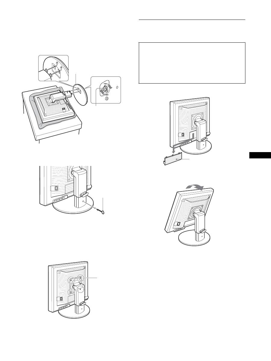
7
FR
FR
5
Encliquetez les parties en saillie du support sur les
orifices de la base du support afin de fixer cette
dernière.
1
Soulevez la poignée de la vis pour visser
correctement la base du support.
2
Assurez-vous que la vis est serrée et retournez la
poignée de la vis.
6
Retirez la goupille d’arrêt après avoir levé
verticalement le support à hauteur réglable.
Remarque
Ne retirez pas la goupille d’arrêt aussi longtemps que le support
demeure couché. Il risquerait de tomber ou de vous blesser si son
attache venait à se détacher de la base de manière impromptue.
x
En cas d’utilisation du support VESA
Vous pouvez fixer un support VESA d’une autre marque en
retirant le support fourni qui est déjà fixé à l’écran.
Étape 2 : Raccordez les câbles de
signal vidéo
1
Abaissez le couvercle des connecteurs en le faisant
glisser.
2
Inclinez l’écran vers le haut.
Ensuite, relevez l’angle de l’écran.
1
Base du support
2
Vis
Goupille d’arrêt
Vis compatibles
avec la norme
VESA (4)
• Mettez l’écran et l’ordinateur hors tension avant de
procéder au raccordement.
Remarques
• Ne touchez pas les broches du connecteur du câble de signal vidéo,
car vous risquez de les plier.
• Vérifiez l’alignement du connecteur pour ne pas tordre les broches
du connecteur du câble de signal vidéo.
Couvercle des connecteurs
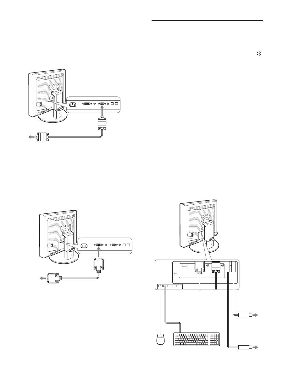
8
3
Raccordez les câbles de signal vidéo à l’écran.
x
Raccordez un ordinateur équipé d’un
connecteur de sortie HD15 (RVB
analogique)
À l’aide du câble de signal vidéo HD15-HD15 fourni (RVB
analogique), raccordez l’ordinateur au connecteur d’entrée
HD 15 de l’écran (RVB analogique).
x
Raccordez un ordinateur équipé d’un
connecteur de sortie DVI (RVB numérique)
Raccordez l’ordinateur au connecteur d’entrée DVI-D de
l’écran (RVB numérique) à l’aide du câble de signal vidéo
DVI-D (RVB numérique) fourni.
Étape 3 : Raccordez la souris USB
ou le clavier USB ou
d’autres périphériques
(modèles équipés de
ports USB uniquement)
En raccordant la souris USB ou le clavier USB ou d’autres
périphériques, vous pouvez permuter les entrées (fonction KVM).
Pour plus d’informations, reportez-vous à la section « Fonction
KVM » (page 18).
Si vous n’utilisez pas de souris USB ou de clavier USB ou
d’autres périphériques avec votre écran, passez à l’Étape 4.
1
Raccordez le câble fourni entre l’écran et l’ordinateur.
2
Raccordez la souris USB ou le clavier USB ou
d’autres périphériques à l’écran.
Pour l’utilisateur Macintosh :
Si vous raccordez le port USB Downstream au clavier d’un
Macintosh équipé d’un bouton de marche, celui-ci risque de
ne plus commander la mise sous tension. Actionnez le bouton
de marche de votre ordinateur ou raccordez directement le
clavier à l’ordinateur, puis mettez-le sous tension et raccordez
ensuite le port USB Downstream au clavier.
Remarques
• Le port USB de cet écran est compatible avec Windows 2000 / Windows
XP Professionnel / Windows XP Édition familiale / Macintosh.
• Si la souris USB ou le clavier USB ou d’autres périphériques sont déjà
raccordés à votre ordinateur, débranchez une fois la souris USB ou le
clavier USB ou les autres périphériques.
• Cette procédure est réservée aux ordinateurs et aux systèmes
d’exploitation compatibles USB. Pour plus d’informations, reportez-
vous au mode d’emploi de votre ordinateur ou de votre système
d’exploitation.
câble de signal vidéo HD15-HD15
(RVB analogique) (fourni)
vers le connecteur de sortie HD15 de
l’ordinateur (RVB analogique)
vers le connecteur
d’entrée HD 15
(RVB analogique)
vers le connecteur de sortie DVI
de l’ordinateur (RVB numérique)
vers le connecteur
d’entrée DVI-D
(RVB numérique)
câble de signal vidéo
DVI-D (RVB
numérique) (fourni)
AC IN
DVI-D
HD15
1
2
2
1
Vers port USB
de l’ordinateur
Vers port USB
de l’ordinateur
Câble USB
(fourni)
Câble USB (fourni)
Souris USB
Clavier USB
2
2
1
1
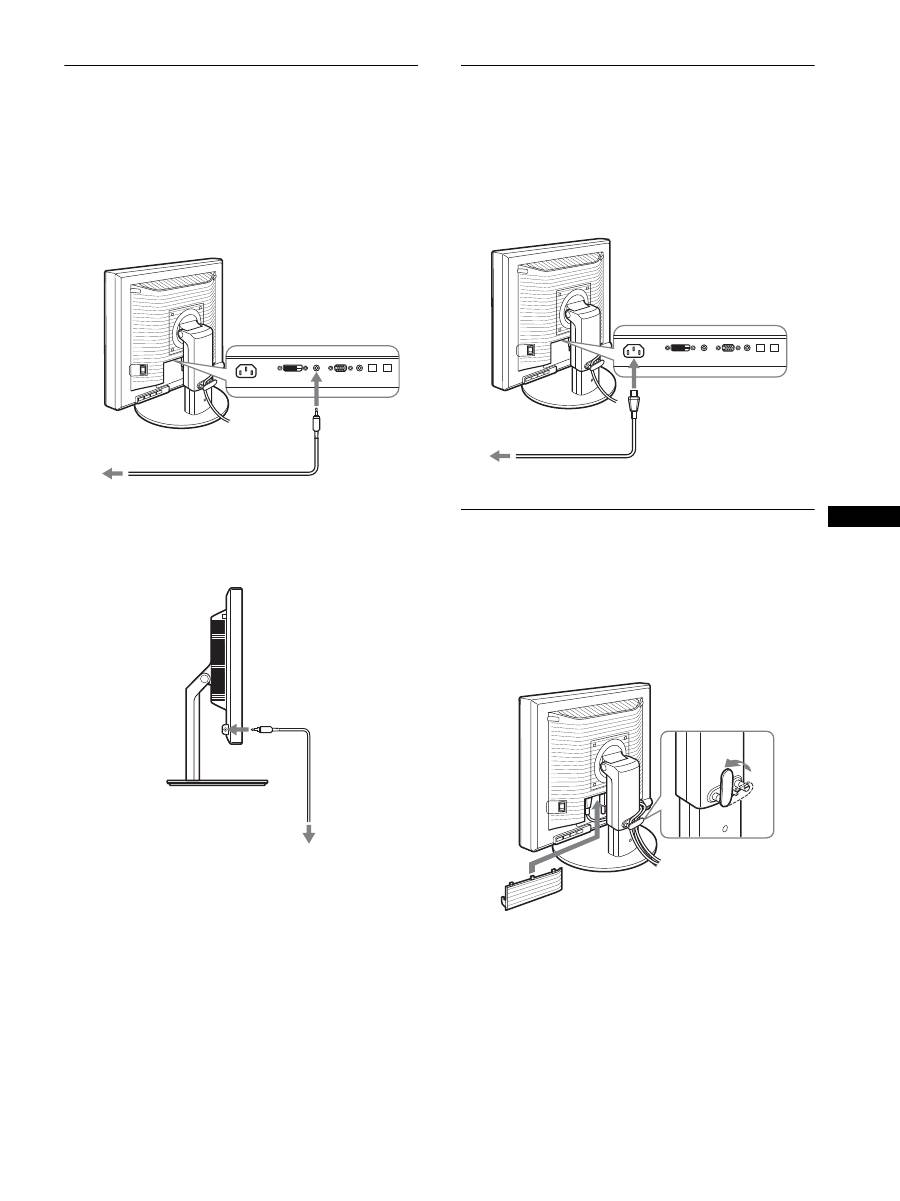
9
FR
FR
Étape 4 : Raccordez les cordons
audio
Si vous ne souhaitez pas reproduire le son, vous n’avez
pas besoin de ce raccordement.
1
Raccordez la prise d’entrée audio de l’écran et la
prise de sortie audio de l’ordinateur ou d’un autre
appareil audio à l’aide du cordon audio fourni.
2
Raccordez le câble audio (non fourni) correctement
à la prise de sortie audio de l’écran.
La sortie audio sera modifiée dès que le raccordement de la sortie
audio et de l’entrée audio de l’écran sera terminé.
Raccordez l’appareil audio situé dans la plage d’entrée reprise
dans les caractéristiques d’entrée audio de l’écran. Si le niveau
d’entrée est trop élevé, l’écran risque d’être endommagé.
Étape 5 : Branchez le cordon
d’alimentation
1
Raccordez solidement le cordon d’alimentation
fourni au connecteur AC IN de l’écran.
2
Raccordez solidement l’autre extrémité du cordon à
une prise secteur.
Étape 6 : Fixez les cordons et
refermez le couvercle des
connecteurs
1
Faites passer les cordons et les câbles à travers le
support de câble, de la manière illustrée.
2
Refermez le couvercle des connecteurs.
Remarque
Lorsque vous rassemblez les cordons et les câbles, veillez à laisser un peu
de jeu. S’ils sont trop tendus, ils risquent de se détacher des connecteurs
ou des prises quand vous réglez l’angle de l’écran. Si vous tirez trop fort
sur les cordons et les câbles, vous risquez de les endommager.
vers l’entrée audio
cordon audio (fourni)
vers la sortie audio de
l’ordinateur ou d’un autre
appareil audio
vers l’entrée audio
cordon audio
(fourni)
Cordon d’alimentation (fourni)
vers AC IN
vers une prise secteur
2
1
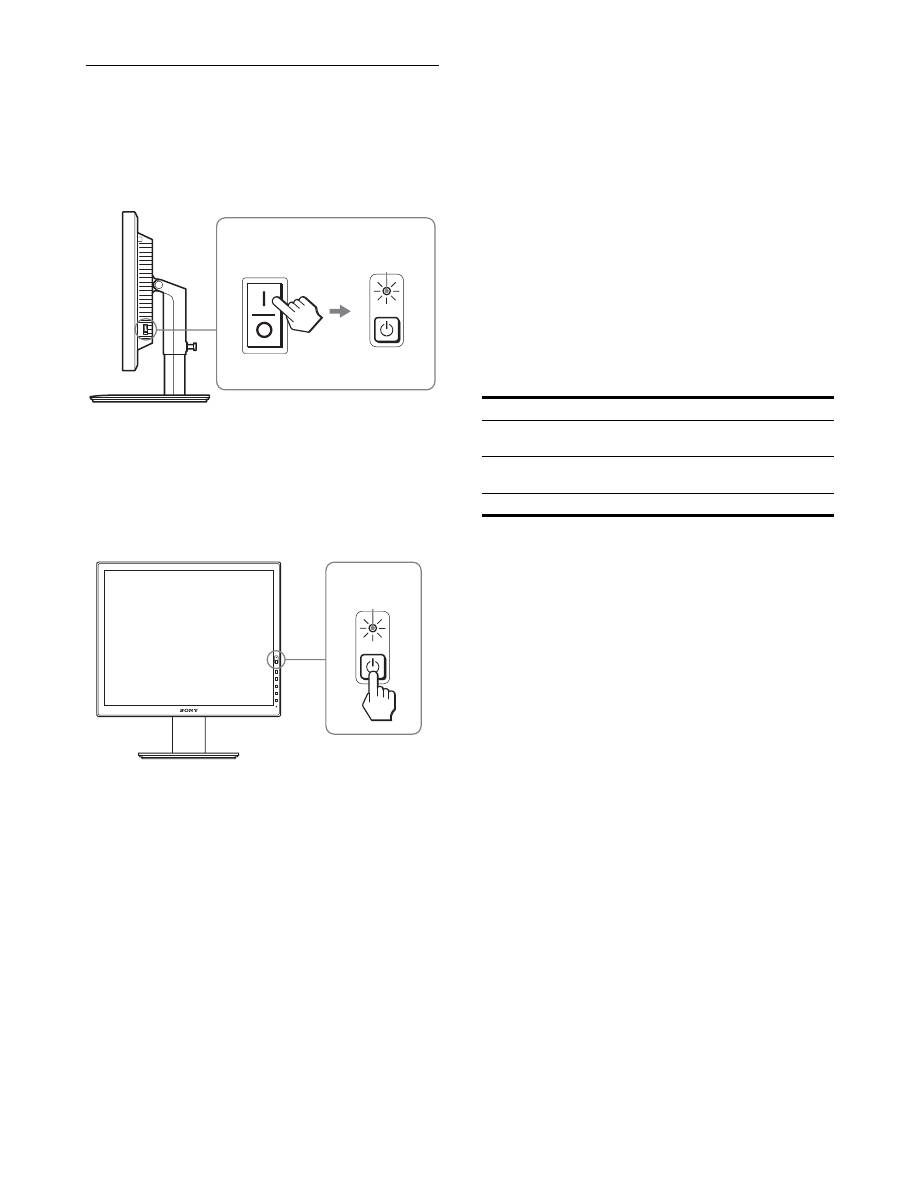
10
Étape 7 : Mettez l’écran et
l’ordinateur sous tension
1
Assurez-vous que l’indicateur
1
(alimentation)
clignote en rouge. Au moment de l’achat, le côté
\
de
l’interrupteur MAIN POWER est enfoncé.
Remarque
Si le côté
\
de l’interrupteur MAIN POWER situé sur le côté droit de
l’écran n’est pas enfoncé, appuyez dessus et assurez-vous que le témoin
1
(alimentation) clignote en rouge.
2
Appuyez sur le commutateur
1
(alimentation) situé
à droite, à l’avant de l’écran.
L’indicateur
1
(alimentation) s’allume en vert.
3
Mettez l’ordinateur sous tension.
Si aucune image n’apparaît sur l’écran
• Vérifiez que le cordon d’alimentation et le câble du signal
vidéo sont correctement raccordés.
• Si l’indication
« PAS
D’ENTRÉE VIDÉO »
apparaît sur
l’écran :
– L’ordinateur est en mode d’économie d’énergie. Essayez
d’appuyer sur n’importe quelle touche du clavier ou déplacez la
souris.
– Vérifiez que le réglage du signal d’entrée est correct en
appuyant sur la touche OK (page 12).
• Si l’indication
«
CABLE NON CONNECTÉ
»
apparaît sur
l’écran :
– Vérifiez que les câbles vidéo sont bien raccordés.
– Vérifiez que le réglage du signal d’entrée est correct en
appuyant sur la touche OK (page 12).
• Si l’indication
«
HORS PLAGE FRÉQUENCES
»
apparaît
sur l’écran :
Reconnectez l’ancien écran. Réglez ensuite la carte graphique
de l’ordinateur dans les plages suivantes.
Pour des informations plus détaillées sur les messages à l’écran,
voir « Symptômes de défaillances et remèdes » à la page 20.
Vous n’avez besoin d’aucun pilote pour cet écran
L’écran prend en charge la fonction Plug & Play « DDC » et détecte
automatiquement toutes les autres informations relatives à l’écran. Il n’est
pas nécessaire d’installer de pilote pour cet ordinateur.
La première fois que vous mettez l’ordinateur sous tension après avoir
raccordé l’écran, l’assistant d’installation peut s’afficher sur l’écran. Dans
ce cas, suivez les indications affichées à l’écran. L’écran Plug & Play est
automatiquement sélectionné afin que vous puissiez l’utiliser.
La fréquence verticale devient 60 Hz.
Etant donné que les scintillements sur l’écran ne sont pas gênants, vous
pouvez l’utiliser tel quel. Vous n’avez pas besoin de régler la fréquence
verticale sur une valeur particulièrement élevée.
MAIN POWER
L’indicateur
s’allume
en rouge
L’indicateur
s’allume en vert
RVB analogique
RVB numérique
Fréquence
horizontale
28 – 92 kHz
28 – 75 kHz
Fréquence
verticale
48 – 85 Hz
60 Hz
Résolution
1 600
×
1 200 ou moins
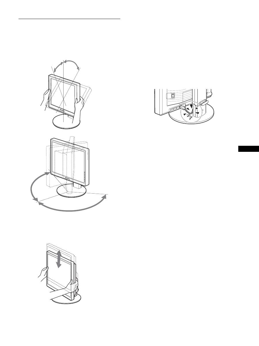
11
FR
FR
Étape 8 : Réglez l’inclinaison et la
hauteur
Cet écran peut être ajusté selon les angles illustrés ci-dessous.
Maintenez le panneau LCD par les deux côtés puis
réglez les angles d’inclinaison de l’écran.
Lorsque vous utilisez le support à hauteur réglable, la hauteur peut
aussi être réglée de la manière décrite ci-dessous.
Saisissez l’écran LCD des deux côtés, puis réglez sa
hauteur.
Pour une utilisation confortable de l’écran
Ajustez l’angle de vision de votre écran selon la hauteur de votre
bureau et de votre siège de sorte que l’écran ne réfléchisse pas la
lumière dans les yeux.
Remarques
• Lorsque vous réglez la position de l’écran, veillez à ne heurter aucun
écran, câble ou périphérique USB environnant. Veillez à déplacer
délicatement l’écran.
• Ne placez aucun objet sous l’écran lorsque vous réglez la hauteur du
support. Il risquerait d’être endommagé accidentellement.
• Lorsque vous raccordez des produits USB ou des périphériques USB à
l’écran, veillez à ce qu’ils ne heurtent pas la base du support. En
fonction de leur taille, les produits et périphériques risquent
d’endommager l’écran lorsque vous réglez son inclinaison et sa
hauteur. (modèles équipés de ports USB uniquement)
environ 20°
environ 5°
environ
175°
environ
175°
Support à hauteur réglable
environ 110 mm
(4
11
/
32
pouces)
Support pivotant
environ 130 mm
(5
1
/
8
pouces)
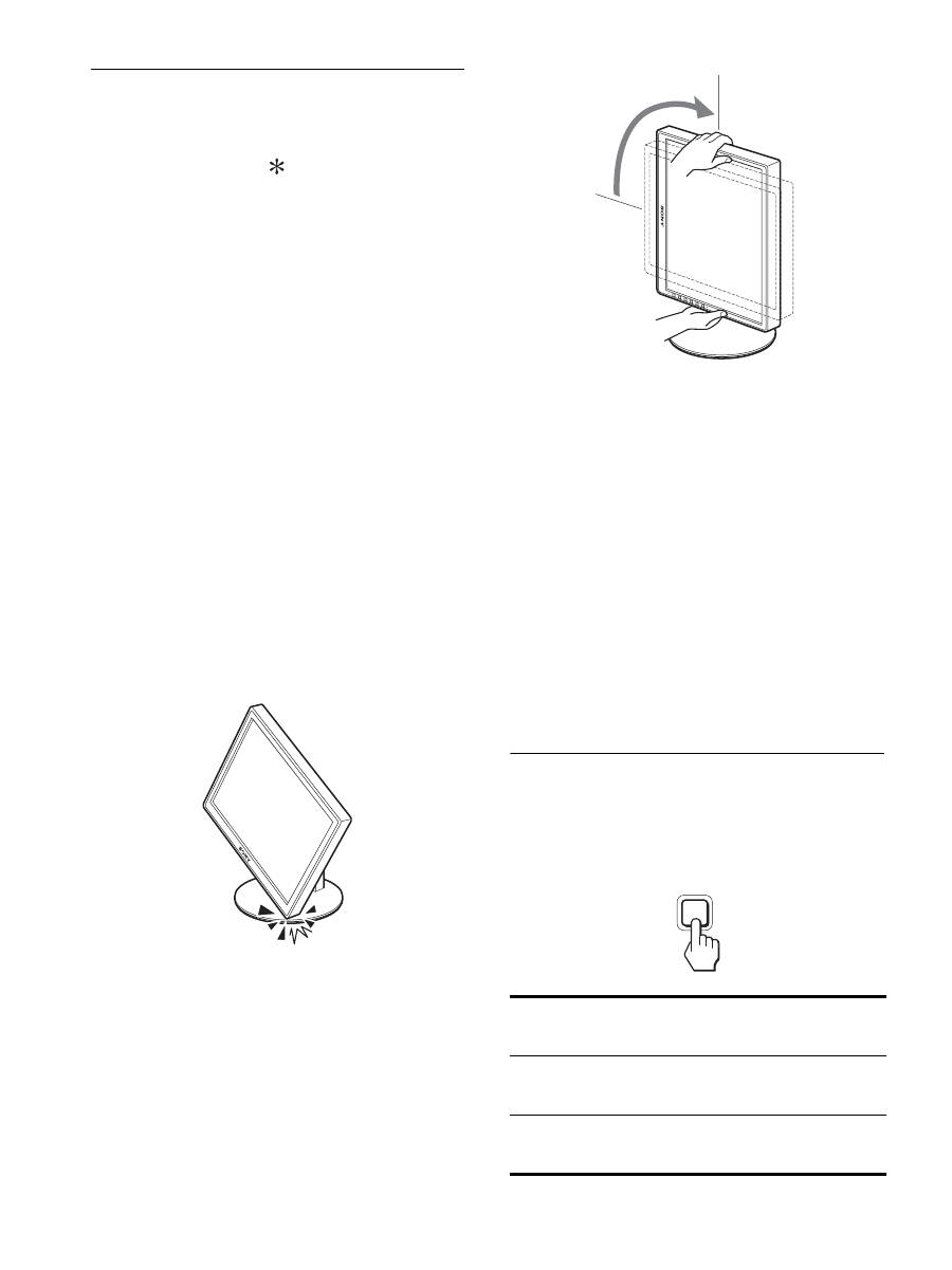
12
Basculement de votre image entre
portrait/paysage (Uniquement pour
les modèles auquel un support
pivotant est fixé)
Si votre ordinateur est doté d’une fonction de basculement de
l’écran entre portrait/paysage, vous pouvez faire pivoter l’écran
de 90°.
Commencez par ajuster les réglages de basculement des images
sur votre ordinateur, puis faites pivoter l’écran.
Rotation de l’écran en portrait
1
Sur votre ordinateur, ajustez les réglages pour faire
pivoter l’écran de 90° dans le sens inverse des
aiguilles d’une montre.
2
Appuyez sur la touche MENU de l’écran, puis
sélectionnez « ROTATION MENU » dans le menu
OPTION et sélectionnez « PORTRAIT ».
Vous pouvez modifier la position d’affichage du menu en
fonction de la disposition de l’écran.
3
Saisissez les deux côtés de l’écran et soulevez-le
lentement jusqu’à ce qu’il atteigne sa position la
plus élevée.
Remarques
• Si vous faites pivoter l’écran raccordé au dispositif USB ou à des
produits compatibles USB, vous risquez de l’endommager.
• Si vous faites pivoter l’écran, veillez à ne heurter aucun écran,
câble ou périphérique USB environnant. Veillez à déplacer
délicatement l’écran.
• Si vous faites pivoter l’écran, retirez tous les câbles du support de
câble, puis déplacez-les délicatement sans tirer trop fort.
4
Saisissez les deux côtés de l’écran et faites-le
pivoter lentement de 90° dans le sens des aiguilles
d’une montre.
Vous ne pouvez pas faire pivoter l’écran de plus de 90
°
.
5
Saisissez les deux côtés de l’écran et réglez sa
hauteur ainsi que son inclinaison.
Pour remettre l’écran à plat
1
Sur votre ordinateur, ajustez les réglages pour faire
pivoter l’écran de 90° dans le sens des aiguilles
d’une montre.
2
Appuyez sur la touche MENU de l’écran, puis
sélectionnez « ROTATION MENU » dans le menu
OPTION et sélectionnez « PAYSAGE ».
Replacez l’affichage du menu en position horizontale.
3
Saisissez les deux côtés de l’écran et soulevez-le
lentement jusqu’à ce qu’il atteigne sa position la
plus élevée.
4
Saisissez les deux côtés de l’écran et faites-le
pivoter lentement de 90° dans le sens inverse des
aiguilles d’une montre.
Sélection du signal d’entrée
(INPUT1/INPUT2)
Appuyez sur la touche OK.
Le signal d’entrée change chaque fois que vous appuyez sur la
touche OK.
Message à l
’
écran (s
’
affiche
pendant environ 5 secondes
dans le coin supérieur gauche)
Configuration du signal en
entrée
ENTRÉE1 : DVI-D
Connecteur d
’
entrée DVI-D
(RVB numérique) pour
INPUT1
ENTRÉE2 : HD15
Connecteur d
’
entrée HD15
(RVB analogique) pour
INPUT2
INPUT
OK
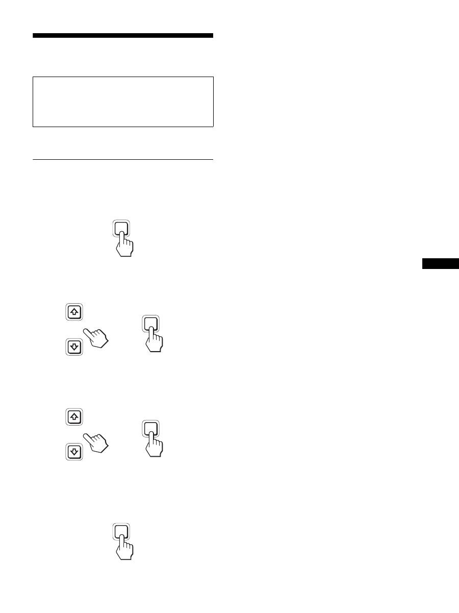
13
FR
FR
Personnalisation de votre
écran
Vous pouvez effectuer de nombreux réglages de votre écran à
l’aide des menus affichés.
Pilotage par menu
1
Affichez le menu principal.
Appuyez sur la touche MENU pour afficher le menu principal
sur votre écran.
2
Sélectionnez le menu que vous souhaitez régler.
Appuyez sur les touches
m
/
M
pour afficher le menu de votre
choix. Appuyez sur la touche OK pour sélectionner un
paramètre.
3
Réglez l’option.
Appuyez sur les touches
m
/
M
pour effectuer votre réglage,
puis appuyez sur la touche OK.
Lorsque vous appuyez sur OK, le réglage est mémorisé et
l’appareil revient au menu précédent.
4
Refermez le menu.
Appuyez une fois sur la touche MENU pour revenir en mode
de visualisation normale. Si vous n’actionnez aucune touche,
le menu se referme automatiquement au bout d’environ
45 secondes.
x
Réinitialisation des réglages à leurs valeurs
par défaut
Vous pouvez réinitialiser les réglages à l’aide du menu
RÉINITIALISATIO.
Pour plus d’informations sur la réinitialisation des réglages, voir
0
(RÉINITIALISATIO) à la page 17.
Avant de procéder aux réglages
Raccordez l’écran et l’ordinateur, puis mettez-les sous tension.
Pour obtenir des résultats optimaux, attendez au moins
30 minutes avant d’effectuer des réglages après avoir raccordé
l’écran à l’ordinateur et l’avoir mis sous tension.
MENU
INPUT
OK
,
INPUT
OK
,
MENU
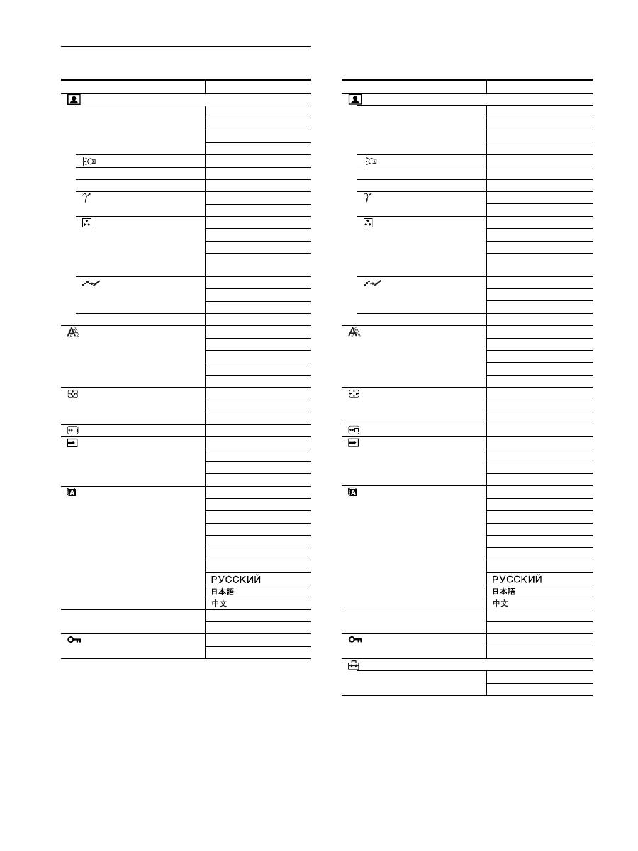
14
Liste des éléments de menu
1)
Lorsque le mode ECO est réglé sur « AUTOMATIQUE », vous ne
pouvez pas régler le RETROÉCLAIRAGE.
2)
CONTRASTE, LUMINOSITÉ et GAMMA ne peuvent pas être
sélectionnés lorsque « sRGB » est sélectionné.
SDM-S205F
Menu RÉGLAGE IMAGE
MODE (Mode-ECO)
HAUT
MOYEN
BAS
AUTOMATIQUE
1)
RETROÉCLAIRAGE
;
1)
6
CONTRASTE
;
1) 2)
8
LUMINOSITÉ
;
2)
GAMMA
UTILISATEUR
2)
CAL.
2)
COULEUR
9300K
6500K
sRGB
2)
UTILISATEUR
(GAIN et BIAS)
LISSAGE
TEXTE
STANDARD
GRAPHIQUE
0
REINIT. DU MODE
;
ÉCRAN
AUTOMATIQUE
PHASE
HORLOGE
CENTRAGE H
CENTRAGE V
ZOOM
PLEIN
GARDER ASPECT
RÉEL
POSITION MENU
;
DÉTECTE ENTRÉE
AUTO ACTIVÉE
ENTRÉE1
ENTRÉE2
AUTO DESACTIV
LANGUAGE
ENGLISH
FRANÇAIS
DEUTSCH
ESPAÑOL
ITALIANO
NEDERLANDS
SVENSKA
0
RÉINITIALISATIO
OK
ANNULER
VERROU DU MENU
ACTIF
INACTIF
SDM-S205K
Menu RÉGLAGE IMAGE
MODE (Mode-ECO)
HAUT
MOYEN
BAS
AUTOMATIQUE
1)
RETROÉCLAIRAGE
;
1)
6
CONTRASTE
;
1) 2)
8
LUMINOSITÉ
;
2)
GAMMA
UTILISATEUR
2)
CAL.
2)
COULEUR
9300K
6500K
sRGB
2)
UTILISATEUR
(GAIN et BIAS)
LISSAGE
TEXTE
STANDARD
GRAPHIQUE
0
REINIT. DU MODE
;
ÉCRAN
AUTOMATIQUE
PHASE
HORLOGE
CENTRAGE H
CENTRAGE V
ZOOM
PLEIN
GARDER ASPECT
RÉEL
POSITION MENU
;
DÉTECTE ENTRÉE
AUTO ACTIVÉE
ENTRÉE1
ENTRÉE2
AUTO DESACTIV
LANGUAGE
ENGLISH
FRANÇAIS
DEUTSCH
ESPAÑOL
ITALIANO
NEDERLANDS
SVENSKA
0
RÉINITIALISATIO
OK
ANNULER
VERROU DU MENU
ACTIF
INACTIF
OPTION
ROTATION MENU
PAYSAGE
PORTRAIT
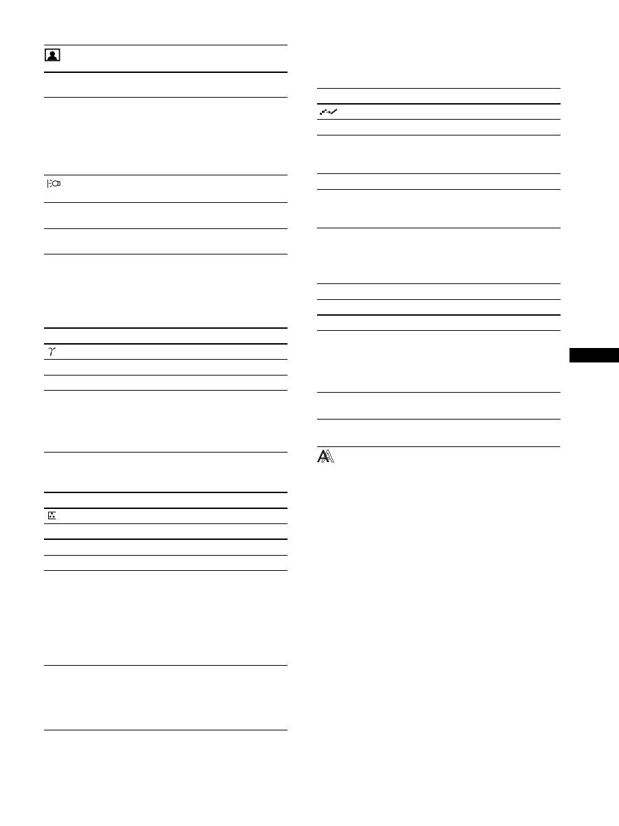
15
FR
FR
Menu RÉGLAGE IMAGE
Remarques
• Lorsque le mode ECO est réglé sur « AUTOMATIQUE », vous ne
pouvez pas régler le RETROÉCLAIRAGE.
• Si vous sélectionnez « sRGB », vous ne pouvez pas régler le
CONTRASTE et la LUMINOSITÉ.
Remarque
Si vous sélectionnez « sRGB », vous ne pouvez pas régler le GAMMA.
1)
Si un ordinateur ou un autre appareil raccordé à l’écran n’est pas compatible
sRGB, les couleurs ne peuvent pas être ajustées sur le profil sRGB.
Lorsque vous sélectionnez « sRGB », vous ne pouvez pas ajuster
CONTRASTE, LUMINOSITÉ et GAMMA.
Si vous avez réglé le mode ECO sur « AUTOMATIQUE », vous ne
pouvez pas sélectionner « sRGB ».
Remarque
Vous ne pouvez pas utiliser la fonction LISSAGE quand le signal possède
la résolution 1 600 × 1 200.
Menu ÉCRAN (signal RVB
analogique uniquement)
x
Fonction de réglage automatique de la
qualité de l’image
Lorsque l’affichage reçoit un signal d’entrée, il ajuste
automatiquement la position et la netteté de l’image
(phase/horloge). Il garantit ainsi la qualité de l’image
qui apparaît sur l’écran (page 18).
Remarque
Lorsque la fonction de réglage automatique de la qualité l’image est
activée, seul le commutateur
1
(alimentation) fonctionne.
Si la fonction de réglage automatique de la qualité de
l’image de cet écran semble ne pas régler
complètement l’image
Vous pouvez effectuer un autre réglage automatique de la qualité
de l’image pour le signal d’entrée réglé. (Voir
« AUTOMATIQUE » ci-dessous.)
Si vous souhaitez encore effectuer d’autres réglages
fins de la qualité de l’image
Vous pouvez régler manuellement la netteté (phase/horloge) et la
position (horizontale/verticale) de l’image.
Ces réglages sont mémorisés et apparaissent automatiquement
lorsque l’écran reçoit le même signal d’entrée. Ces réglages
Éléments
Appuyez sur la
touche
M
Appuyez sur la
touche
m
MODE
Réglez le mode ECO.
Sélectionnez la luminosité de l’écran en
choisissant HAUT, MOYEN, BAS et
AUTOMATIQUE pour économiser
l’énergie.
Vous pouvez réglez divers modes en
sélectionnant une entrée.
HAUT
MOYEN
BAS
AUTOMATIQUE
RETROÉCLAIRAGE
Éclaircit l’écran.
Assombrit l’écran.
6
CONTRASTE
Accentue le
contraste de l’image.
Réduit le contraste
de l’image.
8
LUMINOSITÉ
Illumine l’image
(niveau de noir).
Assombrit l’image
(niveau de noir).
Éléments
GAMMA
Options
Caractéristiques
UTILISATEUR
Règle les couleurs des images.
CAL.
Ce mode règle un état gamma brut pour
l’écran LCD. Pour obtenir le meilleur
étalonnage possible, validez ce mode
lorsque vous utilisez un système
d’étalonnage couleur externe.
Éléments
COULEUR
Options
Caractéristiques
9300K
Teinte bleutée
6500K
Teinte rougeâtre
sRGB
1)
Lorsque vous sélectionnez « sRGB », les
couleurs sont ajustées en fonction du
profil sRGB. (Le réglage des couleurs
sRGB est un protocole d’espace
colorimétrique conforme aux normes
industrielles.) Lorsque vous sélectionnez
« sRGB », les réglages des couleurs de
votre ordinateur doivent être ajustés sur
le profil sRGB.
UTILISATEUR
Vous pouvez effectuer des réglages
supplémentaires afin d’éclaircir certaines
zones (GAIN : niveau de blanc) et en
assombrir d’autres (BIAS : niveau de
noir). Vous pouvez également mémoriser
la couleur définie.
Éléments
LISSAGE
Options
Caractéristiques
TEXTE
Pour afficher plus clairement les
caractères (Ce mode convient aux
applications qui affichent du texte).
STANDARD
Effet de lissage standard.
GRAPHIQUES
Pour afficher plus clairement les images
(Ce mode convient aux photos et aux
illustrations).
Éléments
0
RÉINIT. DU MODE
Options
Caractéristiques
OK
Vous pouvez réinitialiser les réglages
RÉTROÉCLAIRAGE, CONTRASTE,
LUMINOSITÉ, GAMMA et
COULEUR en rétablissant leur valeur
par défaut.
ANNULER
Annule la réinitialisation et revient au
menu.
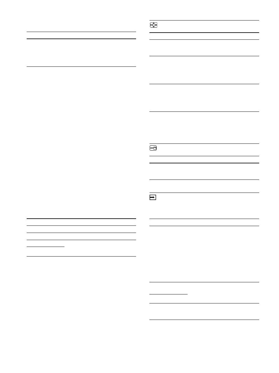
16
doivent éventuellement être répétés si vous changez de signal
d’entrée après avoir rebranché votre ordinateur.
x
Ajustez la netteté et la position de l’image
manuellement (PHASE/HORLOGE/
CENTRAGE H/CENTRAGE V)
Vous pouvez ajuster la netteté et la position de l’image, comme suit.
1
Réglez la résolution sur 1 600 × 1 200 sur
l’ordinateur.
2
Chargez le CD-ROM.
3
Démarrez le CD-ROM et affichez la mire de test.
Pour l’utilisateur Windows
Si le démarrage automatique est activé :
1
Cliquez sur « Outil de réglage d’affichage (UTILITY) ».
2
Cliquez sur « Adjust » et vérifiez la résolution, puis cliquez
sur « Next ».
Les mires de test de PHASE/HORLOGE/CENTRAGE H/
CENTRAGE V s’affichent successivement.
Si le démarrage automatique échoue :
1
Ouvrez « Poste de travail » et cliquez avec le bouton droit
sur l’icône du CD-ROM. Cliquez sur « Explorer » et
ouvrez l’icône du CD-ROM.
2
Ouvrez [Utility], puis sélectionnez [Windows].
3
Démarrez [Win_Utility.exe].
La mire de test s’affiche.
Pour l’utilisateur Macintosh
1
Ouvrez [Utility], puis sélectionnez [Mac].
2
Démarrez [Mac_Utility.exe].
La mire de test s’affiche.
Menu ZOOM
Remarque
Vous ne pouvez pas utiliser cette fonction quand le signal possède la
résolution 1 600 × 1 200. L’image est affichée en plein écran.
Menu POSITION MENU
Menu DÉTECTE ENTRÉE
Vous pouvez rechercher n’importe quels signaux d’entrée, en les
commutant automatiquement.
Éléments
Caractéristiques
AUTOMATIQUE
Procédez aux réglages appropriés de la
phase, de l’horloge et de la position
horizontale/verticale de l’écran pour le
signal d’entrée en cours et enregistrez-
les.
Éléments
Appuyez sur les touches
m
/
M
PHASE
Réduisez les rayures horizontales à l’écran.
HORLOGE
Les rayures verticales disparaissent.
CENTRAGE H
Ajustez la position de l’image lorsque
votre image n’apparaît pas au centre de
l’écran.
CENTRAGE V
Éléments
Caractéristiques
PLEIN
Le signal d’entrée est affiché en plein
écran quel que soit le mode ou la
résolution de l’image.
GARDER ASPECT Le signal d’entrée est affiché dans son
rapport d’aspect effectif. Des bandes
noires peuvent alors apparaître au-dessus
et en dessous de l’image, en fonction du
signal.
RÉEL
Le signal d’entrée est affiché dans sa
résolution effective. Les signaux d’une
résolution inférieure à 1 600 × 1 200
sont affichés au centre de l’écran,
entourés d’un cadre noir.
Éléments
Appuyez sur les touches
m
/
M
POSITION MENU
Vous pouvez modifier la position
d’affichage du menu à l’écran. Vous avez
le choix entre l’une des 9 positions.
Éléments
Caractéristiques
AUTO ACTIVÉE
Si l’entrée sélectionnée n’a pas de signal
ou si vous sélectionnez une entrée avec
la touche OK et qu’elle n’a pas de signal
d’entrée, un message s’affiche sur
l’écran (page 19). L’écran vérifie alors le
signal d’entrée et bascule
automatiquement vers l’autre entrée.
Lorsque l’entrée est commutée, l’entrée
sélectionnée est affichée dans le coin
supérieur gauche de l’écran.
Lorsque aucun signal n’est capté, l’écran
passe en mode de veille.
ENTRÉE 1
A la mise sous tension de l’écran,
ENTRÉE1 ou ENTRÉE2 apparaît
comme réglage prioritaire (DÉTECTE
ENTRÉE ne fonctionne pas).
ENTRÉE 2
AUTO DESACTIV
L’entrée n’est pas changée
automatiquement. Appuyez sur la touche
OK pour changer l’entrée.
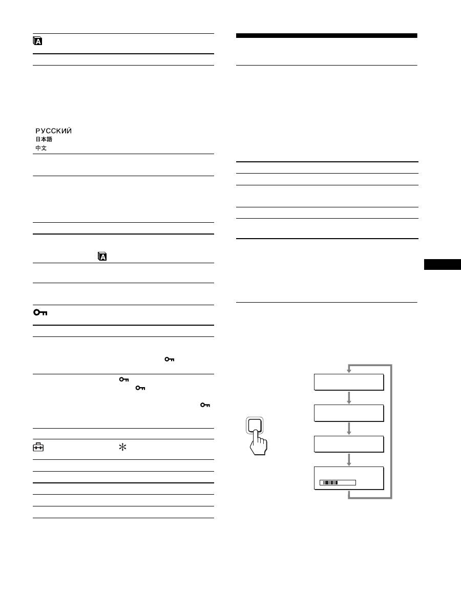
17
FR
FR
Menu LANGUAGE
0
Menu RÉINITIALISATIO
(réinitialisation aux valeurs par
défaut)
Menu VERROU DU MENU
Menu OPTION
Spécifications techniques
Fonction d’économie d’énergie
Cet écran satisfait aux critères d’économie d’énergie VESA,
E
NERGY
S
TAR et NUTEK. Si l’écran est raccordé à un
ordinateur ou à une carte graphique vidéo compatible DPMS
(Display Power Management Standard) pour une entrée
analogique/compatible DMPM (DVI Digital Monitor Power
Management) pour une entrée numérique, l’écran réduit
automatiquement sa consommation d’énergie comme indiqué ci-
dessous.
1)
Lorsque votre ordinateur passe en mode
« inactif »
, le signal d’entrée
est coupé est l’indication PAS D’ENTRÉE VIDÉO apparaît sur
l’écran. Au bout de 5 secondes, l’écran passe en mode d’économie
d’énergie.
« sommeil profond » est un mode d’économie d’énergie défini par
l’Environmental Protection Agency.
Réduction de la consommation
électrique
(Mode-ECO)
Si vous appuyez à plusieurs reprises sur la touche ECO située à
l’avant de l’écran, vous pouvez sélectionner la luminosité de
l’écran.
Chaque mode apparaît sur l’écran et la luminosité de celui-ci est
réduite en fonction du mode. Le menu disparaît automatiquement
dans les cinq secondes.
La luminosité de l’écran et la consommation électrique sont
réduites suivant le changement de mode, de HAUT à MOYEN et
à BAS.
Le réglage par défaut de la luminosité de l’écran est fixé à HAUT.
Éléments
Appuyez sur les touches
m
/
M
ENGLISH
FRANÇAIS
DEUTSCH
ESPAÑOL
ITALIANO
NEDERLANDS
SVENSKA
Anglais
Allemand
Espagnol
Italien
Néerlandais
Suédois
Russe
Japonais
Chinois
Éléments
Caractéristiques
OK
Réinitialise toutes les données de réglage
à leurs valeurs par défaut sauf celles du
(LANGUAGE).
ANNULER
Annule la réinitialisation et revient à
l’écran de menu.
Éléments
Caractéristiques
ACTIF
Seul le
1
commutateur d’alimentation
1
est actif. Si vous tentez de lancer une
autre opération, l’icône
(VERROU
DU MENU) apparaît sur l’écran.
INACTIF
Réglez
(VERROU DU MENU) sur
INACTIF. Si
(VERROU DU
MENU) est réglé sur ACTIF, lorsque
vous appuyez sur la touche MENU,
(VERROU DU MENU) est
automatiquement sélectionné.
Éléments
ROTATION MENU
Options
Caractéristiques
PAYSAGE
Affiche l’écran dans la position paysage.
PORTRAIT
Affiche l’écran dans la position portrait.
Mode d’alimentation
Indicateur
1
(alimentation)
fonctionnement normal
vert
inactif
1)
(sommeil profond)
orange
hors tension
rouge
alimentation principale
hors tension
éteint
ECO
5 0
E C O
H AU T
:
E C O
M OY E N
:
E C O
B A S
:
E C O
AU TO M AT I Q U E
:
,

18
Fonction de réglage automatique de
la luminosité (capteur de lumière)
Cet écran est doté d’une fonction de réglage automatique de la
luminosité de l’écran, en fonction de la luminosité ambiante. La
luminosité de l’écran est réglée au niveau le plus approprié par
réglage du mode ECO sur AUTOMATIQUE avec la touche ECO
située à l’avant de l’écran ou avec le menu RÉGLAGE IMAGE.
Par défaut, la luminosité de l’écran est réglée sur HAUT. De même,
lorsque vous réglez le mode ECO sur « AUTOMATIQUE » avec
la touche ECO située sur le panneau avant de l’écran, la barre de
réglages s’affiche également. Vous pouvez régler la barre avec les
touches
m
/
M
. La luminosité de l’écran change selon le niveau que
vous réglez.
Fonction de réglage automatique
de la qualité de l’image
(signal RVB
analogique uniquement)
Lorsque l’écran reçoit un signal d’entrée, il ajuste
automatiquement la position et la précision de
l’image (phase/horloge) et garantit la qualité de
l’image qui apparaît sur l’écran.
Le mode préréglé par défaut
Lorsque l’écran reçoit un signal d’entrée, il fait automatiquement
correspondre le signal à l’un des modes préréglés par défaut,
enregistrés dans la mémoire de l’écran afin de produire une image
de haute qualité au centre de l’écran. Si le signal d’entrée
correspond au mode préréglé par défaut, l’image apparaît
automatiquement sur l’écran, avec le réglage par défaut
approprié.
Si certains signaux d’entrée ne correspondent à
aucun mode préréglé par défaut
Lorsque l’écran reçoit un signal d’entrée qui ne correspond à
aucun mode préréglé par défaut, la fonction de réglage
automatique de la qualité de l’image de cet écran est activée et
garantit l’affichage permanent d’une image claire sur l’écran
(dans les plages de fréquences suivantes de l’écran) :
Fréquence horizontale : 28–92 kHz (RVB analogique)
28–75 kHz (RVB numérique)
Fréquence verticale :
48–85 Hz (RVB analogique)
60 Hz (RVB numérique)
En conséquence, la première fois que l’écran reçoit des signaux
d’entrée qui ne correspondent pas à l’un des modes préréglés par
défaut, il se peut que l’affichage de l’image à l’écran prenne plus
de temps. Ces données de réglages sont automatiquement
enregistrées dans la mémoire de sorte que l’écran fonctionnera de
la même manière la prochaine fois qu’il recevra des signaux
correspondants à l’un des modes préréglés par défaut.
Si vous ajustez la phase, l’horloge et la position
des images manuellement
Pour certains signaux d’entrée, la fonction de réglage
automatique de la qualité de l’image de cet écran peut ne pas
ajuster complètement la position, la phase et l’horloge de l’image.
Dans ce cas, vous pouvez effectuer ces réglages manuellement
(page 16). Si vous effectuez ces réglages manuellement, ils sont
mémorisés comme des modes utilisateurs et sont
automatiquement rappelés lorsque l’écran reçoit les mêmes
signaux d’entrée.
Remarque
Pendant que la fonction de réglage de la qualité d’image automatique est
activée, seul le commutateur
1
(alimentation) fonctionnera.
Fonction KVM (Fonction Clavier-
Vidéo-Souris)
Vous pouvez utiliser jusqu’à deux ordinateurs et permuter leur
souris USB et leur clavier USB (page 8) à l’aide de la touche
INPUT/OK.
À propos du port USB
• Nous vous recommandons de connecter la souris USB et le
clavier USB au port USB de l’écran. Si vous connectez d’autres
périphériques que ceux-ci, l’écran risque de ne pas fonctionner
correctement. Ou les périphériques compatibles Bluetooth
risquent de ne pas fonctionner correctement.
• Le port USB de l’écran est compatible USB Full-Speed
(12 Mbits/s max.).
Remarques
• Même si vous appuyez sur la touche INPUT/OK, vous risquez de ne
pas pouvoir basculer assez rapidement entre les ordinateurs.
• Pour utiliser les périphériques USB, installez le pilote USB le plus
récent. Un pilote USB obsolète risque de ne pas fonctionner
correctement.
• Lorsque vous utilisez un concentrateur USB, réglez les signaux
d’entrée sur AUTO DESACTIV dans le menu DÉTECTE ENTRÉE.
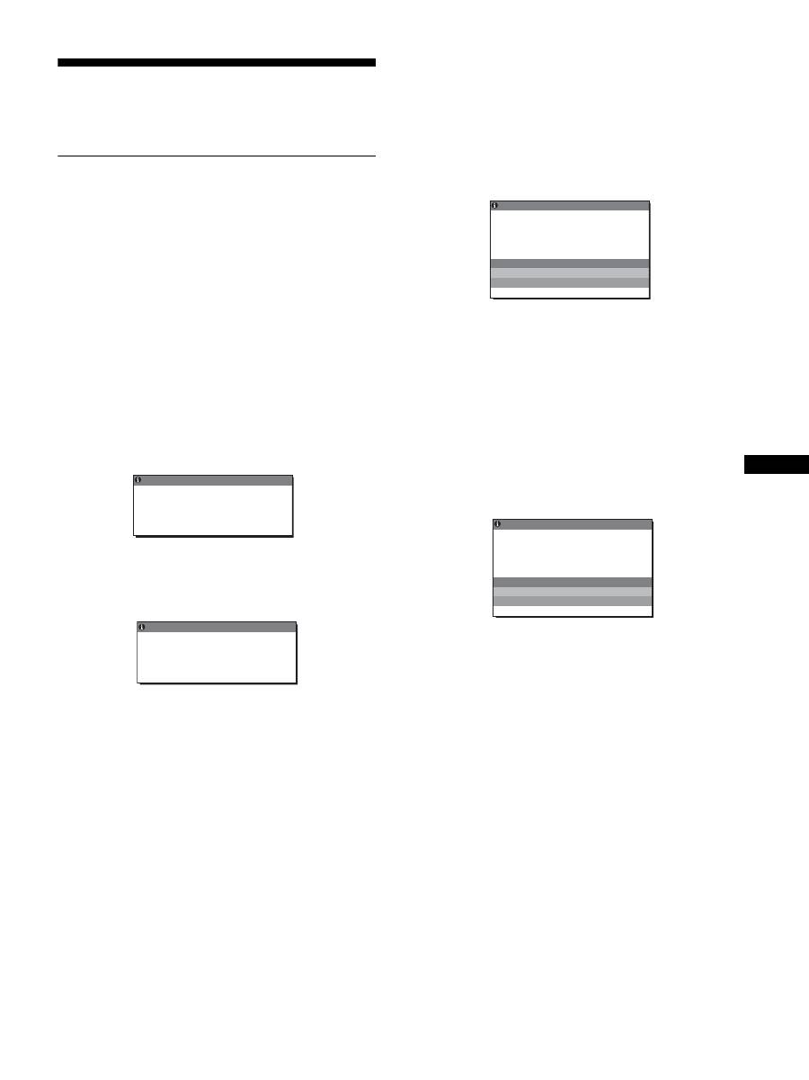
19
FR
FR
Dépannage
Avant de prendre contact avec l’assistance technique, parcourez
les informations présentées dans cette section.
Messages affichés
S’il se produit une anomalie au niveau du signal d’entrée, l’un des
messages suivants apparaît sur l’écran. Pour résoudre le
problème, voir « Symptômes de défaillances et remèdes » à la
page 20.
Si l’indication « HORS PLAGE FRÉQUENCES »
apparaît sur l’écran
Cela signifie que le signal transmis n’est pas pris en charge par les
spécifications de l’écran. Vérifiez les éléments suivants.
Pour des informations détaillées sur les messages à l’écran,
voir « Symptômes de défaillances et remèdes » à la page 20.
Si « xxx.xkHz/ xxxHz » est affiché
Cela signifie que la fréquence horizontale ou verticale n’est
pas prise en charge par les spécifications de l’écran.
Les chiffres indiquent les fréquences horizontales et
verticales du signal d’entrée en cours.
Si « RÉSOLUTION > 1600
×
1200 » est affiché
Cela signifie que la résolution n’est pas prise en charge par les
spécifications de l’écran (1 600
×
1 200 ou moins).
Si l’indication « PAS D’ENTRÉE VIDÉO » apparaît
sur l’écran
Cela signifie qu’aucun signal n’est détecté en entrée via le
connecteur actuellement sélectionné.
Lorsque DÉTECTE ENTRÉE (page 16) est réglé sur ACTIF,
l’écran détecte un autre signal d’entrée et commute
automatiquement la source d’entrée.
En l’absence de signaux d’entrée, le message
«
PASSE EN MODE ÉCO
»
s’affiche. Le passage en mode d’économie d’énergie
intervient 5 secondes plus tard environ.
Si l’indication « CABLE NON CONNECTÉ »
apparaît sur l’écran
Cela signifie que le câble de signal vidéo a été déconnecté du
connecteur actuellement sélectionné.
Lorsque DÉTECTE ENTRÉE (page 16) est réglé sur ACTIF,
l’écran détecte un autre signal d’entrée et commute
automatiquement la source d’entrée.
En l’absence de signaux d’entrée, le message
«
PASSE EN MODE ÉCO
»
s’affiche. Le passage en mode d’économie d’énergie
intervient 45 secondes plus tard environ.
FR QUENC S
E
HORS P L AGE
ENTRÉ
É
E 1 : DV I -
x x x . x k H z /
x x x
D
H z
I NFORMA T I ONS
Exemple
Exemple
I NFORMA T I ONS
H O R S P L AG E
R É S O L U T I O N > 1 6 0 0 X 1 2 0 0
E N T RÉE 1 : D V I - D
FR QUENC S
E
É
CAB L E NON CONNECT É
I NFORMA T I ONS
ENTRÉE 1 : DV I - D
PASSE EN MODE ÉCO
Exemple
CAB L E NON CONNECT É
I NFORMA T I ONS
ENTRÉE 1 : DV I - D
PASSE EN MODE ÉCO
Exemple

20
Symptômes de défaillances et remèdes
Si un problème est causé par un ordinateur ou un autre appareil raccordé, reportez-vous aux modes d’emploi de l’appareil ou de l’ordinateur concerné.
Symptôme
Vérifiez ces éléments
Pas d’image
Si l’indicateur
1
(alimentation)
n’est pas allumé ou si l’indicateur
1
(alimentation) ne s’allume pas
lorsque vous appuyez sur le
commutateur
1
(alimentation) :
• Vérifiez que le cordon d’alimentation est correctement raccordé.
• Assurez-vous que l’interrupteur MAIN POWER de l’écran est bien sous tension
(page 10).
Si l’indicateur
1
(alimentation)
s’allume en rouge :
• Vérifiez que le commutateur
1
(alimentation) est activé.
Si « CABLE NON CONNECTÉ »
apparaît sur l’écran :
• Vérifiez que le câble de signal vidéo est correctement raccordé et que toutes les fiches sont
correctement branchées dans leur prise (page 7).
• Vérifiez que les broches du connecteur d’entrée vidéo ne sont pas pliées ou enfoncées.
• Vérifiez que le réglage de sélection d’entrée est correct (page 12).
• Un câble de signal vidéo non fourni est raccordé. Si vous raccordez un câble de signal
vidéo non fourni, l’indication CABLE NON CONNECTÉ peut apparaître sur l’écran. Il ne
s’agit pas d’un problème de fonctionnement.
Si le message d’avertissement « PAS
D’ENTRÉE VIDÉO » apparaît sur
l’écran, ou, si l’indicateur
1
(alimentation) vire à l’orange :
• Vérifiez que le câble de signal vidéo est correctement raccordé et que toutes les fiches sont
correctement branchées dans leur prise (page 7).
• Vérifiez que les broches du connecteur d’entrée vidéo ne sont pas pliées ou enfoncées.
• Vérifiez que le réglage de sélection d’entrée est correct (page 12).
x
Problèmes causés par un ordinateur ou un autre appareil raccordé et non
par l’écran
• L’ordinateur est en mode d’économie d’énergie. Appuyez sur une touche quelconque du
clavier ou déplacez la souris.
• Vérifiez que votre carte graphique est correctement installée.
• Vérifiez que l’alimentation de l’ordinateur est activée.
• Redémarrez l’ordinateur.
Si « HORS PLAGE
FRÉQUENCES » apparaît sur
l’écran (page 19) :
x
Problèmes causés par un ordinateur ou un autre appareil raccordé et non
par l’écran
• Vérifiez que la plage de fréquence vidéo est comprise dans la plage spécifiée pour l’écran.
Si vous avez remplacé un ancien écran par cet écran, rebranchez l’ancien, puis ajustez la
carte graphique de l’ordinateur dans les plages suivantes :
Horizontale : 28 à 92 kHz (RVB analogique), 28 à 75 kHz (RVB numérique)
Verticale : 48 à 85 Hz (RVB analogique), 60 Hz (RVB numérique)
Résolution : 1 600
×
1 200 ou moins
Si vous utilisez Windows :
• Si vous avez remplacé votre ancien écran par cet écran, rebranchez l’ancien écran et suivez
la procédure suivante. Sélectionnez « SONY » dans la liste « Fabricants », puis
sélectionnez le nom de modèle souhaité dans la liste « Modèles » dans l’écran de sélection
de périphériques Windows. Si le nom de modèle de cet écran n’apparaît pas dans la liste
« Modèles », essayez « Plug & Play ».
Si vous utilisez un système
Macintosh :
• En cas de raccordement d’un ordinateur Macintosh, utilisez si nécessaire un adaptateur (non
fourni). Raccordez l’adaptateur à l’ordinateur avant de raccorder le câble du signal vidéo.
L’image scintille, sautille, oscille
ou est brouillée
• Ajustez l’horloge et la phase (signal RVB analogique uniquement) (page 16).
• Branchez l’écran sur une autre prise secteur, de préférence reliée à un autre circuit.
x
Problèmes causés par un ordinateur ou un autre appareil raccordé et non
par l’écran
• Consultez le mode d’emploi de votre carte graphique pour le réglage approprié de l’écran.
• Assurez-vous que le mode graphique (VESA, Macintosh 19” Color, etc.) et la fréquence
du signal d’entrée sont pris en charge par cet écran. Même si la fréquence est comprise
dans la plage appropriée, il se peut que certaines cartes vidéo offrent une impulsion de
synchronisation trop étroite pour que l’écran se synchronise correctement.
• Cet écran ne traite pas les signaux entrelacés. Utilisez des signaux progressifs.
• Ajustez le taux de régénération de l’ordinateur (fréquence verticale) de manière à obtenir
la meilleure image possible.
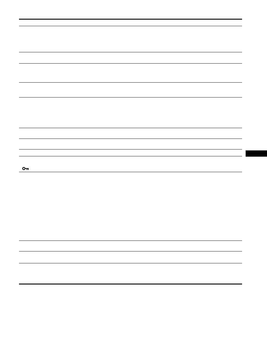
21
FR
FR
L’image est floue
• Ajustez la luminosité et le contraste (page 15).
• Ajustez l’horloge et la phase (signal RVB analogique uniquement) (page 16).
x
Problèmes causés par un ordinateur ou un autre appareil raccordé et non
par l’écran
•
Réglez la résolution sur votre ordinateur à 1 600
×
1 200.
Apparition d’images fantômes
• N’utilisez pas de prolongateurs de câble vidéo et/ou de boîtiers de commutation vidéo.
• Vérifiez si toutes les fiches sont correctement branchées sur leur prise.
L’image n’est ni centrée
correctement, ni au bon format
(signal RVB analogique
uniquement)
• Ajustez l’horloge et la phase (page 16).
• Ajustez la position de l’image (page 16). Notez que certains modes vidéo ne remplissent
pas l’écran jusqu’aux bords.
L’image est trop petite
x
Problèmes causés par un ordinateur ou un autre appareil raccordé et non
par l’écran
• Réglez la résolution sur votre ordinateur à 1 600
×
1 200.
L’image est sombre
• Réglez le rétroéclairage (page 15).
• Réglez la luminosité (page 15).
•
Ajustez le réglage gamma à l’aide du menu GAMMA (
page 15
).
• Plusieurs minutes sont nécessaires avant que l’écran ne devienne lumineux après sa mise
sous tension.
• L’écran peut s’assombrir en fonction du mode ECO sélectionné.
Apparition d’un motif ondulatoire
ou elliptique (moiré)
• Ajustez l’horloge et la phase (signal RVB analogique uniquement) (page 16).
Les couleurs ne sont pas
uniformes
• Ajustez l’horloge et la phase (signal RVB analogique uniquement) (page 16).
Le blanc ne semble pas blanc
• Réglez la température des couleurs (page 15).
Les touches de l’écran sont
inopérantes
(
apparaît sur l’écran)
• Si
VERROU DU MENU
est réglé sur ACTIF, réglez-le sur INACTIF (page 17).
Le périphérique raccordé par
l’intermédiaire du câble USB ne
fonctionne pas
• Vérifiez que le câble USB (fourni) est correctement raccordé (page 8).
• Appuyez sur l’interrupteur MAIN POWER et l’indicateur
1
(alimentation) pour mettre
l’écran sous tension.
x
Problèmes provoqués par votre ordinateur ou d’autres périphériques
raccordés
• Vérifiez que votre périphérique est bien sous tension.
• Réinstallez le pilote USB mis à jour. Pour plus d’informations, contactez le fabricant du
produit.
• Si vous ne parvenez pas à utiliser l’ordinateur avec le clavier ou la souris raccordés à
l’écran, raccordez-les directement à l’ordinateur. Après avoir redémarré votre ordinateur,
réinitialisez la connexion USB. Une fois cette procédure terminée, rebranchez le clavier et
la souris sur l’écran. Lorsque l’écran est raccordé à un ordinateur, un clavier ou une souris
via le port USB, vous risquez de ne pas pouvoir commander votre ordinateur à partir de
ceux-ci lorsque vous le redémarrez.
L’écran se met hors tension au
bout d’un moment
x
Problèmes causés par l’ordinateur ou tout autre équipement connecté
• Désactivez le mode d’économie d’énergie de l’ordinateur.
La résolution affichée dans l’écran
de menu est incorrecte
• Selon le paramétrage de la carte graphique, il est possible que la résolution affichée dans
l’écran de menu ne corresponde pas à celle de l’ordinateur.
Après avoir mis l’écran hors
tension, l’indicateur
1
(alimentation) reste allumé
pendant un moment
• Lorsque l’écran est sous tension mais que le commutateur
1
(alimentation) n’est pas
enfoncé ou lorsque l’écran est en mode d’économie d’énergie, si vous désactivez le
commutateur MAIN POWER, il se peut que l’indicateur
1
(alimentation) ne s’éteigne pas
immédiatement. Il ne s’agit pas d’un dysfonctionnement.
Symptôme
Vérifiez ces éléments
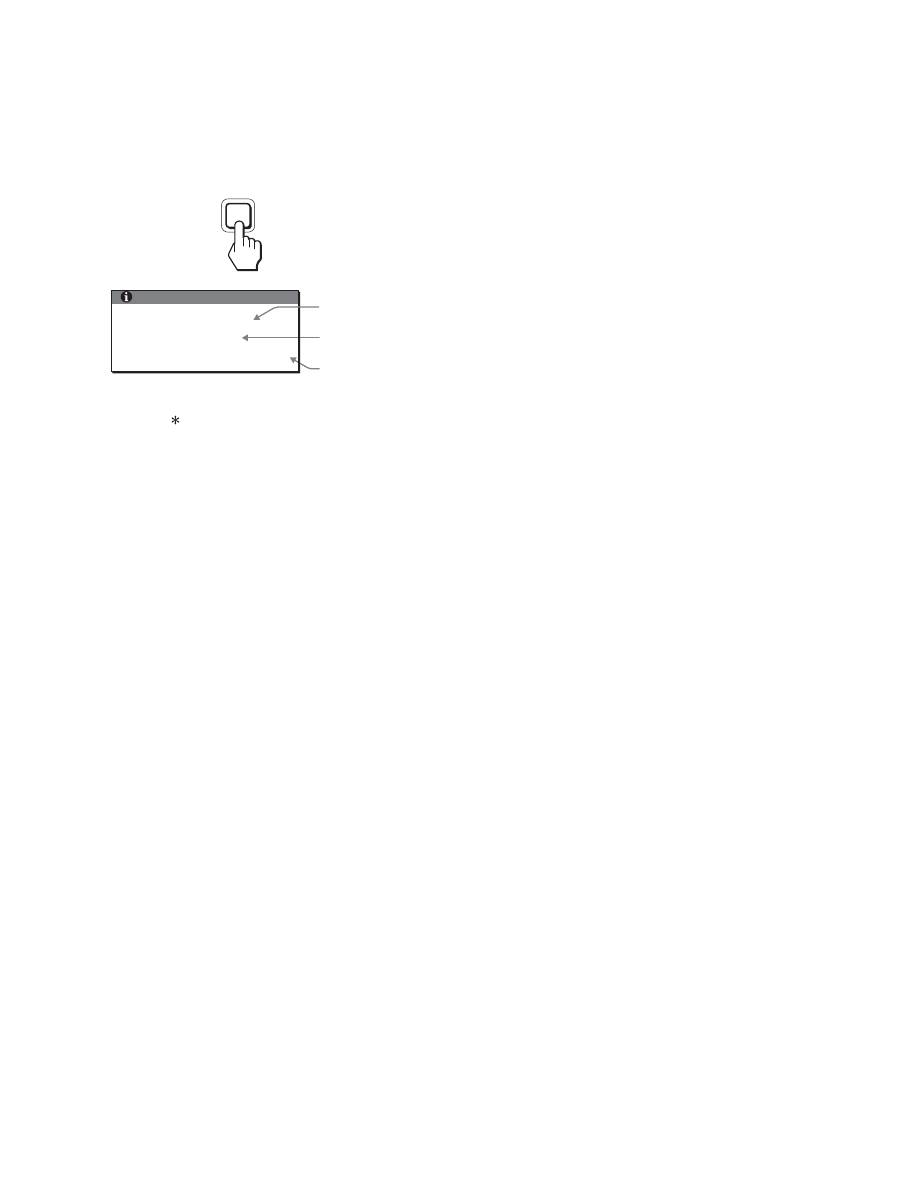
22
Affichage des informations de l’écran
Lorsque l’écran reçoit un signal vidéo, appuyez sur la
touche MENU et maintenez-la enfoncée pendant plus
de 5 secondes jusqu’à ce que la boîte de dialogue
d’informations s’affiche.
Appuyez de nouveau sur la touche MENU pour faire disparaître
la boîte de dialogue.
Bien que le nom de modèle enregistré pour les normes de sécurité
soit SDM-S205 , les noms SDM-S205F/S205K sont utilisés lors
de la vente.
Si le problème persiste, appelez votre revendeur Sony agréé et
fournissez-lui les informations suivantes :
• Désignation
• Numéro de série
• Description détaillée du problème
• Date d’achat
• Nom et spécifications de votre ordinateur et de votre carte
graphique
• Types de signaux d’entrée (RVB analogique/RVB numérique)
INFORMATIONS
MODEL : SDM-S205F
SER. NO : 1234567
MANUFACTURED : 2005-52
MENU
Exemple
Désignation
Numéro de série
Semaine et année
de fabrication
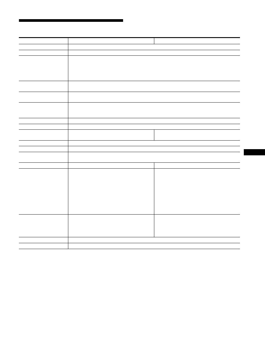
23
FR
FR
Spécifications
1)
Condition de synchronisation horizontale et verticale recommandée
• La largeur de synchronisation horizontale doit être
supérieure de plus de 4,8% à la durée horizontale totale ou
0,8 µs, suivant la plus grande valeur.
• La largeur de suppression horizontale doit être supérieure à
2,5 µs.
• La largeur de suppression verticale doit être supérieure à
450 µs.
La conception et les spécifications sont sujettes à modifications
sans préavis.
Nom du modèle
SDM-S205F
SDM-S205K
Panneau LCD
Type de panneau : a-Si TFT à matrice active
Taille de l'image : pouces
20,1
Format du signal d’entrée
Fréquence opérationnelle RVB
1)
Horizontale : 28 – 92 kHz (RVB analogique)
28 – 75 kHz (RVB numérique)
Verticale : 48 – 85 Hz (RVB analogique)
60 Hz (RVB numérique)
Résolution
Horizontale : Max. 1 600 points
Verticale : Max. 1 200 lignes
Type de signal d’entrée
(Numérique/Analogique)
Numérique × 1/Analogique × 1
Niveaux des signaux
d’entrée
Signal vidéo RVB 0,7 Vp-p, 75
Ω
, positif
Signal SYNC Niveau TTL, 2,2 k
Ω
, positif ou négatif
Signal RVB numérique (DVI) : TMDS (lien simple)
Entrée audio
Mini-prise stéréo, 0,5 V eff.
Sortie audio
Mini-prise stéréo
Port USB
–
USB Full-Speed (12 Mbits/s max.)
Port A × 4, Port B × 2
Puissance de raccordement
100 – 240 V, 50 – 60 Hz, Max. 1,2 A
Consommation électrique
Max. 55 W
Température de
fonctionnement
5 – 35 °C
Type de support
Hauteur réglable
Pivotant
Dimensions (largeur/
hauteur/profondeur)
environ 441,5 × 410,5 – 520,5 × 277,5 mm
(17
3
/
8
× 16
1
/
4
– 20
1
/
2
× 11 pouces)
(avec support)
environ 441,5 × 356,5 × 74 mm
(17
3
/
8
× 14
1
/
8
× 2
7
/
8
pouces)
(sans support)
environ 441,5 × 421 – 551 × 277,5 mm
(17
3
/
8
× 16
5
/
8
– 21
3
/
4
× 11 pouces)
(avec support (position normale))
environ 356,5 × 470,5 – 600,5 × 277,5 mm
(14
1
/
8
× 18
5
/
8
– 23
3
/
4
× 11 pouces)
(avec support (position après pivotement))
environ 441,5 × 356,5 × 74 mm
(17
3
/
8
× 14
1
/
8
× 2
7
/
8
pouces)
(sans support)
Masse
environ 9,6 kg (21 lb 2
3
/
8
oz)
(avec support)
environ 6,0 kg (13 lb 3
3
/
8
oz)
(sans support)
environ 9,9 kg (21 lb 12
3
/
16
oz)
(avec support)
environ 6,1 kg (13 lb 6
3
/
5
oz)
(sans support)
Plug & Play
DDC2B
Accessoires
Voir page 6.

i
TCO’99 Eco-document (for the black
model)
x
Congratulations!
You have just purchased a TCO’99 approved and labelled product! Your
choice has provided you with a product developed for professional use.
Your purchase has also contributed to reducing the burden on the
environment and also to the further development of environmentally
adapted electronics products.
x
Why do we have environmentally labelled com-
puters?
In many countries, environmental labelling has become an established
method for encouraging the adaptation of goods and services to the
environment. The main problem, as far as computers and other electronics
equipment are concerned, is that environmentally harmful substances are
used both in the products and during their manufacture. Since it is not so
far possible to satisfactorily recycle the majority of electronics equipment,
most of these potentially damaging substances sooner or later enter nature.
There are also other characteristics of a computer, such as energy
consumption levels, that are important from the viewpoints of both the
work (internal) and natural (external) environments. Since all methods of
electricity generation have a negative effect on the environment (e.g.
acidic and climate-influencing emissions, radioactive waste), it is vital to
save energy. Electronics equipment in offices is often left running
continuously and thereby consumes a lot of energy.
x
What does labelling involve?
This product meets the requirements for the TCO’99 scheme which
provides for international and environmental labelling of personal
computers. The labelling scheme was developed as a joint effort by the
TCO (The Swedish Confederation of Professional Employees), Svenska
Naturskyddsforeningen (The Swedish Society for Nature Conservation)
and Statens Energimyndighet (The Swedish National Energy
Administration).
Approval requirements cover a wide range of issues: environment,
ergonomics, usability, emission of electric and magnetic fields, energy
consumption and electrical and fire safety.
The environmental demands impose restrictions on the presence and use
of heavy metals, brominated and chlorinated flame retardants, CFCs
(freons) and chlorinated solvents, among other things. The product must
be prepared for recycling and the manufacturer is obliged to have an
environmental policy which must be adhered to in each country where the
company implements its operational policy.
The energy requirements include a demand that the computer and/or
display, after a certain period of inactivity, shall reduce its power
consumption to a lower level in one or more stages. The length of time to
reactivate the computer shall be reasonable for the user.
Labelled products must meet strict environmental demands, for example,
in respect of the reduction of electric and magnetic fields, physical and
visual ergonomics and good usability.
Below you will find a brief summary of the environmental requirements
met by this product. The complete environmental criteria document may
be ordered from:
TCO Development
SE-114 94 Stockholm, Sweden
Fax: +46 8 782 92 07
Email (Internet): development@tco.se
Current information regarding TCO’99 approved and labelled
products may also be obtained via the Internet, using the address:
http://www.tco-info.com/
x
Environmental requirements
Flame retardants
Flame retardants are present in printed circuit boards, cables, wires,
casings and housings. Their purpose is to prevent, or at least to delay the
spread of fire. Up to 30% of the plastic in a computer casing can consist
of flame retardant substances. Most flame retardants contain bromine or
chloride, and those flame retardants are chemically related to another
group of environmental toxins, PCBs. Both the flame retardants
containing bromine or chloride and the PCBs are suspected of giving rise
to severe health effects, including reproductive damage in fish-eating
birds and mammals, due to the bio-accumulative
*
processes. Flame
retardants have been found in human blood and researchers fear that
disturbances in foetus development may occur.
The relevant TCO’99 demand requires that plastic components weighing
more than 25 grams must not contain flame retardants with organically
bound bromine or chlorine. Flame retardants are allowed in the printed
circuit boards since no substitutes are available.
Cadmium
**
Cadmium is present in rechargeable batteries and in the colour-generating
layers of certain computer displays. Cadmium damages the nervous
system and is toxic in high doses. The relevant TCO’99 requirement states
that batteries, the colour-generating layers of display screens and the
electrical or electronics components must not contain any cadmium.
Mercury
**
Mercury is sometimes found in batteries, relays and switches. It damages
the nervous system and is toxic in high doses. The relevant TCO’99
requirement states that batteries may not contain any mercury. It also
demands that mercury is not present in any of the electrical or electronics
components associated with the labelled unit.
CFCs (freons)
The relevant TCO’99 requirement states that neither CFCs nor HCFCs
may be used during the manufacture and assembly of the product. CFCs
(freons) are sometimes used for washing printed circuit boards. CFCs
break down ozone and thereby damage the ozone layer in the stratosphere,
causing increased reception on earth of ultraviolet light with e.g. increased
risks of skin cancer (malignant melanoma) as a consequence.
Lead
**
Lead can be found in picture tubes, display screens, solders and
capacitors. Lead damages the nervous system and in higher doses, causes
lead poisoning. The relevant TCO’99 requirement permits the inclusion of
lead since no replacement has yet been developed.
*
Bio-accumulative is defined as substances which accumulate within
living organisms.
** Lead, Cadmium and Mercury are heavy metals which are Bio-
accumulative.

ii
TCO’03 Eco-document (for the silver
model)
x
Congratulations!
The display you have just purchased carries the TCO’03
Displays label. This means that your display is designed,
manufactured and tested according to some of the strictest
quality and environmental requirements in the world. This
makes for a high performance product, designed with the
user in focus that also minimizes the impact on our natural
environment.
x
Ergonomics
• Good visual ergonomics and image quality in order to
improve the working environment for the user and to
reduce sight and strain problems. Important parameters
are luminance, contrast, resolution, reflectance, colour
rendition and image stability.
x
Energy
• Energy-saving mode after a certain time – beneficial
both for the user and the environment
• Electrical safety
x
Emissions
• Electromagnetic fields
• Noise emissions
x
Ecology
• The product must be prepared for recycling and the
manufacturer must have a certified environmental
management system such as EMAS or ISO 14 001
• Restrictions on
- chlorinated and brominated flame retardants and
polymers
- heavy metals such as cadmium, mercury and lead.
The requirements included in this label have been
developed by TCO Development in co-operation with
scientists, experts, users as well as manufacturers all over
the world. Since the end of the 1980s TCO has been
involved in influencing the development of IT equipment
in a more user-friendly direction. Our labelling system
started with displays in 1992 and is now requested by users
and IT-manufacturers all over the world.
For more information, please visit
www.tcodevelopment.com
Recycling Information
x
Customer in Europe
The collection and recycling of this product has been planned
according to your country’s relevant legislation. To ensure that
this product will be collected and recycled in way that minimizes
the impact on the environment, please do the following:
1. If you purchased this product for private use, contact your
municipality or the waste collection system and bring the
product to this collection point / have the product be picked up
by the waste collection system. Alternatively, your retailer
might take back this if you purchase new equivalent equipment;
please check with your retailer whether he will take back this
product before bringing it. For information on your country’s
recycling arrangements, please contact the Sony representation
in your country (contact details at: www.sony-europe.com).
Further details on specific recycling systems can be found at the
following addresses:
- Belgium: www.recupel.be
- Netherlands: www.nvmp.nl (consumer electronics)
www.ictmilieu.nl (IT equipment)
- Norway: www.elretur.no
- Sweden: www.el-kretsen.se
- Switzerland: www.swico.ch
2. If you use this product professionally, check the product’s
delivery contract for take back / recycling arrangements and
follow the procedures described therein. Alternatively, follow
the procedures described under point 1.
x
Customer in USA
We Sony as a member of EIA recommends to visit URL below
http://www.eiae.org/
x
Customer in Asia
http://www.sony.co.jp/SonyInfo/Environment/recycle/3R.html

2-649-019-
04
(1)
© 2005 Sony Corporation
TFT LCD Color Computer Display
SDM-S205
2
Owner’s Record
The model and serial numbers are located at the rear of the unit.
Record these numbers in the spaces provided below. Refer to them
whenever you call upon your dealer regarding this product.
Model No. Serial No.
To reduce the risk of fire or electric shock, do not
expose this apparatus to rain or moisture.
Dangerously high voltages are present inside the
unit. Do not open the cabinet. Refer servicing to
qualified personnel only.
FCC Notice
This equipment has been tested and found to comply with the limits
for a Class B digital device, pursuant to Part 15 of the FCC Rules.
These limits are designed to provide reasonable protection against
harmful interference in a residential installation. This equipment
generates, uses, and can radiate radio frequency energy and, if not
installed and used in accordance with the instructions, may cause
harmful interference to radio communications. However, there is no
guarantee that interference will not occur in a particular installation.
If this equipment does cause harmful interference to radio or
television reception, which can be determined by turning the
equipment off and on, the user is encouraged to try to correct the
interference by one or more of the following measures:
– Reorient or relocate the receiving antenna.
– Increase the separation between the equipment and receiver.
– Connect the equipment into an outlet on a circuit different from
that to which the receiver is connected.
– Consult the dealer or an experienced radio/TV technician for help.
You are cautioned that any changes or modifications not expressly
approved in this manual could void your authority to operate this
equipment.
Bitte prüfen Sie den Lieferumfang des Bildschirms. Das
Typenschild Ihres Bildschirmmodells befindet sich an der
Rückseite des Bildschirms.
(for the black model)
(for the silver model)
WARNING
IMPORTANTE
Para prevenir cualquier mal funcionamiento y evitar daños, por
favor, lea detalladamente este manual de instrucciones antes
de conectar y operar este equipo.
If you have any questions about this product, you may call;
Sony Customer Information Services Center 1-800-222-7669
or http://www.sony.com/
Declaration of Conformity
Trade Name
: SONY
Model
: SDM-S205
Note
: means any number or alphanumeric
character.
Responsible Party
: Sony Electronics Inc.
Address
: 16530 Via Esprillo, San Diego, CA
92127 U.S.A.
Telephone Number : 858-942-2230
This device complies with part 15 of the FCC rules. Operation is
subject to the following two conditions: (1) This device may not
cause harmful interference, and (2) this device must accept any
interference received, including interference that may cause
undesired operation.
NOTICE
This notice is applicable for USA/Canada only.
If shipped to USA/Canada, install only a UL LISTED/CSA
LABELLED power supply cord meeting the following
specifications:
SPECIFICATIONS
Plug Type
Nema-Plug 5-15p
Cord
Type SVT or SJT, minimum 3
×
18 AWG
Length
Maximum 15 feet
Rating
Minimum 7 A, 125 V
NOTICE
Cette notice s’applique aux Etats-Unis et au Canada
uniquement.
Si cet appareil est exporté aux Etats-Unis ou au Canada, utiliser
le cordon d’alimentation portant la mention UL LISTED/CSA
LABELLED et remplissant les conditions suivantes:
SPECIFICATIONS
Type de fiche
Fiche Nema 5-15 broches
Cordon
Type SVT ou SJT, minimum 3
×
18 AWG
Longueur
Maximum 15 pieds
Tension
Minimum 7 A, 125 V
As an
E
NERGY
S
TAR Partner, Sony
Corporation has determined that this
product meets the
E
NERGY
S
TAR
guidelines for energy efficiency.
This monitor complies with the
TCO’99 guidelines.
This monitor complies with the
TCO’03 guidelines.
Inhalt
DE
• Macintosh ist ein Warenzeichen der
Apple Computer, Inc., in den USA und
anderen Ländern.
• Windows
®
ist ein eingetragenes
Warenzeichen der Microsoft
Corporation in den USA und anderen
Ländern.
• IBM PC/AT und VGA sind
eingetragene Warenzeichen der IBM
Corporation in den USA.
• VESA und DDC
™
sind Warenzeichen
der Video Electronics Standards
Association.
•
E
NERGY
S
TAR ist ein eingetragenes
Warenzeichen in den USA.
• Adobe und Acrobat sind Warenzeichen
von Adobe Systems Incorporated.
• Alle anderen in diesem Handbuch
erwähnten Produktnamen können
Warenzeichen oder eingetragene
Warenzeichen der jeweiligen
Eigentümer sein.
• Im Handbuch sind die Warenzeichen
und eingetragenen Warenzeichen nicht
überall ausdrücklich durch
„
™
“
und
„
®
“
gekennzeichnet.
3
http://www.sony.net/
3
Sicherheitsmaßnahmen . . . . . . . . . . . . . . . . . . . . . . . . . . . . . . . . . . 4
Welches Modell haben Sie erworben? . . . . . . . . . . . . . . . . . . . . . . . 5
Lage und Funktion der Teile und Bedienelemente . . . . . . . . . . . . . . 5
Installation . . . . . . . . . . . . . . . . . . . . . . . . . . . . . . . . . . . . .6
Schritt 1:
Zusammenbauen des Ständers . . . . . . . . . . . . . . . . . . . . 6
Schritt 2:
Anschließen der Videosignalkabel . . . . . . . . . . . . . . . . . . 7
Schritt 3:
Anschließen von USB-Maus, USB-Tastatur oder anderen
Geräten (nur bei Modellen mit USB-Anschluss). . . . . . . . 8
Schritt 4:
Anschließen der Audiokabel . . . . . . . . . . . . . . . . . . . . . . 9
Schritt 5:
Anschließen des Netzkabels . . . . . . . . . . . . . . . . . . . . . . 9
Schritt 6:
Befestigen der Kabel und Schließen der
Anschlussabdeckung . . . . . . . . . . . . . . . . . . . . . . . . . . . . 9
Schritt 7:
Einschalten von Bildschirm und Computer . . . . . . . . . . 10
Schritt 8:
Einstellung von Neigung und Höhe . . . . . . . . . . . . . . . . 11
Umschalten des Bildes zwischen Hoch- und Querformat
(nur bei Modellen mit Drehständer) . . . . . . . . . . . . . . . . . . . . . . . . 12
Auswählen des Eingangssignals (INPUT1/INPUT2) . . . . . . . . . . . 12
Einstellen des Bildschirms . . . . . . . . . . . . . . . . . . . . . . .13
Navigieren in den Menüs . . . . . . . . . . . . . . . . . . . . . . . . . . . . . . . . 13
Liste der Menüoptionen . . . . . . . . . . . . . . . . . . . . . . . . . . . . . . . . . 14
Menü BILD EINSTELLEN . . . . . . . . . . . . . . . . . . . . . . . . . . . . 15
Menü BILDSCHIRM (nur bei analogem RGB-Signal) . . . . . . . 15
Menü ZOOM . . . . . . . . . . . . . . . . . . . . . . . . . . . . . . . . . . . . . . 16
Menü POSITION MENÜ . . . . . . . . . . . . . . . . . . . . . . . . . . . . . 16
Menü EINGANGSERKENN . . . . . . . . . . . . . . . . . . . . . . . . . . . 17
Menü LANGUAGE . . . . . . . . . . . . . . . . . . . . . . . . . . . . . . . . . . 17
0
Menü ZURÜCKSETZEN
(zum Zurücksetzen auf die Standardeinstellungen) . . . . . . . . . 17
Menü MENÜ-SPERRE . . . . . . . . . . . . . . . . . . . . . . . . . . . . . . 17
Menü OPTIONEN . . . . . . . . . . . . . . . . . . . . . . . . . . . . . . . . . . 17
Technische Merkmale . . . . . . . . . . . . . . . . . . . . . . . . . . .18
Die Energiesparfunktion . . . . . . . . . . . . . . . . . . . . . . . . . . . . . . . . . 18
Verringern der Leistungsaufnahme (ECO-Modus) . . . . . . . . . . . . . 18
Automatische Helligkeitseinstellung (Lichtsensor) . . . . . . . . . . . . . 18
Automatische Einstellung der Bildqualität
(nur analoges RGB-Signal). . . . . . . . . . . . . . . . . . . . . . . . . . . . . . . 19
Die KVM-Funktion
(Keyboard-Video-Mouse - Tastatur-Video-Maus). . . . . . . . . . . . . . 19
Störungsbehebung . . . . . . . . . . . . . . . . . . . . . . . . . . . . .20
Bildschirmmeldungen . . . . . . . . . . . . . . . . . . . . . . . . . . . . . . . . . . . 20
Fehlersymptome und Abhilfemaßnahmen . . . . . . . . . . . . . . . . . . . 21
Technische Daten . . . . . . . . . . . . . . . . . . . . . . . . . . . . . .24
TCO’99 Eco-document (for the black model) . . . . . . . . . . . . . . . . . . .i
TCO’03 Eco-document (for the silver model) . . . . . . . . . . . . . . . . . . ii
4
Sicherheitsmaßnahmen
Warnhinweis zum Netzanschluss
• Verwenden Sie ausschließlich das mitgelieferte Netzkabel.
Wenn Sie ein anderes Netzkabel verwenden, achten Sie darauf,
dass es für die Stromversorgung in Ihrem Land geeignet ist.
Für Kunden in den USA
Wenn Sie kein geeignetes Netzkabel verwenden, entspricht
dieser Monitor nicht den obligatorischen FCC-Standards.
Für Kunden in Großbritannien
Wenn Sie den Monitor in Großbritannien verwenden, benutzen
Sie bitte das Kabel mit dem für Großbritannien geeigneten
Stecker.
Aufstellort
Achten Sie darauf, dass der Monitor am Aufstell- oder Lagerort
vor folgenden Bedingungen geschützt ist:
• Vor extremen Temperaturen wie sie zum Beispiel in der Nähe
eines Heizkörpers, eines Warmluftauslasses oder in direktem
Sonnenlicht auftreten. Extreme Temperaturen, zum Beispiel in
einem in der Sonne geparkten Auto oder in der Nähe eines
Warmluftauslasses, können bei dem Monitor zu einer
Verformung des Gehäuses oder zu Fehlfunktionen führen.
• Vor mechanischen Vibrationen oder Stößen.
• Vor starken Magnetfeldern. Stellen Sie den Monitor daher
nicht in der Nähe von Geräten auf, die solche Magnetfelder
erzeugen, zum Beispiel Fernsehgeräten oder Haushaltsgeräten.
• Vor übermäßig viel Staub, Schmutz oder Sand, wie sie zum
Beispiel an einem offenen Fenster oder einer Tür ins Freie
auftreten können. Wenn Sie den Monitor vorübergehend im
Freien benutzen müssen, treffen Sie geeignete
Vorsorgemaßnahmen gegen Staub- und Schmutzpartikel in der
Luft. Andernfalls kann es zu irreparablen Schäden am Gerät
kommen.
Achten Sie darauf, die Lüftungsöffnungen oben an der Rückseite
des Bildschirms nicht zu berühren, da diese sich erhitzen können.
Hinweise zum LCD-Bildschirm
• Stellen Sie das Gerät nicht so auf, dass der LCD-Bildschirm auf
die Sonne gerichtet ist. Andernfalls könnte der LCD-
Bildschirm beschädigt werden. Achten Sie darauf besonders,
wenn Sie den Monitor in der Nähe eines Fensters aufstellen.
• Stoßen Sie nicht gegen den LCD-Bildschirm und zerkratzen
Sie ihn nicht. Stellen Sie keine schweren Gegenstände auf den
LCD-Bildschirm. Dadurch könnte die Gleichmäßigkeit des
Bildes beeinträchtigt werden oder am LCD-Bildschirm
könnten Fehlfunktionen auftreten.
• Wenn Sie den Monitor in einer kalten Umgebung benutzen,
kann ein Nachbild auf dem LCD-Bildschirm zu sehen sein.
Dies ist keine Fehlfunktion. Das Phänomen verschwindet,
sobald wieder eine normale Umgebungstemperatur erreicht ist.
• Wenn Sie über längere Zeit ein Standbild anzeigen lassen, kann
eine Zeit lang ein Nachbild zu sehen sein. Dieses Nachbild
verschwindet nach einer Weile wieder.
• Der Bildschirm erwärmt sich bei Betrieb. Dies ist keine
Fehlfunktion.
Hinweis zum LCD-Bildschirm
(Flüssigkristallbildschirm)
Bitte beachten Sie, dass der LCD-Bildschirm in einer
Hochpräzisionstechnologie hergestellt wird. Schwarze
oder helle Lichtpunkte (rot, blau oder grün) können
jedoch permanent auf dem LCD-Bildschirm zu sehen
sein und unregelmäßige Farbstreifen oder helle
Bereiche können auf dem LCD-Bildschirm erscheinen.
Dies ist keine Fehlfunktion.
(Effektive Bildpunkte: über 99,99 %)
Wartung
• Trennen Sie unbedingt das Netzkabel von der Netzsteckdose,
bevor Sie den Monitor reinigen.
• Reinigen Sie den LCD-Bildschirm mit einem weichen Tuch.
Wenn Sie ein Glasreinigungsmittel verwenden, achten Sie
darauf, dass es keine Antistatik-Lösung oder ähnliche Zusätze
enthält, da diese zu Kratzern auf der Beschichtung des LCD-
Bildschirms führen könnten.
• Reinigen Sie Gehäuse, Bedienfeld und Bedienelemente mit
einem weichen Tuch, das Sie leicht mit einer milden
Reinigungslösung angefeuchtet haben. Verwenden Sie keine
Scheuermittel, Scheuerschwämme oder Lösungsmittel wie
Alkohol oder Benzin.
• Berühren Sie die LCD-Bildschirmoberfläche nicht mit
scharfen, rauhen oder spitzen Gegenständen wie zum Beispiel
Kugelschreibern oder Schraubenziehern. Andernfalls könnte
die LCD-Bildschirmoberfläche zerkratzt werden.
• Beachten Sie bitte, dass es zu Materialschäden oder zu Schäden
an der LCD-Bildschirmbeschichtung kommen kann, wenn der
Monitor flüchtigen Lösungsmitteln wie zum Beispiel
Insektiziden ausgesetzt ist oder wenn er längere Zeit mit
Gummi- oder Vinylmaterialien in Berühung kommt.
Transport
• Trennen Sie alle Kabel vom Display ab. Wenn Sie einen
höhenverstellbaren Ständer verwenden, stellen Sie diesen auf
die höchste Position ein und halten das LCD-Display an beiden
Seiten gut fest. Achten Sie darauf, dass der Bildschirm beim
Transport nicht verkratzt wird. Ein Fall des Displays kann eine
Verletzung oder eine Beschädigung verursachen.
• Wenn Sie den Monitor zur Reparatur oder bei einem Umzug
transportieren müssen, verpacken Sie ihn mithilfe der
Originalverpackungsmaterialien wieder im Originalkarton.
• Bringen Sie den Anschlagstift des höhenverstellbaren Ständers
wieder an, damit der Ständer während des Transports in der
aktuellen Position fixiert ist.
Entsorgen des Monitors
• Entsorgen Sie den Monitor nicht im normalen
Hausmüll.
• Die Leuchtstoffröhre in diesem Monitor enthält
Quecksilber. Der Monitor muss in Übereinstimmung
mit den Vorschriften der lokalen Umwelt- und
Entsorgungsbehörden entsorgt werden.
Die Netzsteckdose sollte sich in der Nähe des Geräts befinden
und leicht zugänglich sein.
Beispiele für Steckertypen
für 100 bis 120 V
Wechselstrom
für 200 bis 240 V
Wechselstrom
nur für 240 V
Wechselstrom
5
DE
Welches Modell haben Sie
erworben?
Überprüfen Sie bitte als Erstes, welches Modell Sie erworben
haben.
Den Modellnamen finden Sie an der Rückseite des Bildschirms
(Beispiel: SDM-S205F).
Nicht bei allen Bildschirmmodellen stehen alle Geräte- bzw.
Menüfunktionen zur Verfügung.
Lage und Funktion der Teile und
Bedienelemente
Weitere Informationen finden Sie auf den in Klammern
angegebenen Seiten.
Die Abbildung zeigt nur eins der lieferbaren Bildschirmmodelle.
1
Netzschalter
1
und Netzanzeige
1
(Seiten 10, 18)
Wenn die Netzanzeige
1
rot leuchtet, dient dieser Schalter
zum Einschalten des Bildschirms. Drücken Sie diesen
Schalter erneut, um den Bildschirm wieder auszuschalten.
Wenn die Netzanzeige
1
nicht leuchtet, drücken Sie den
Hauptnetzschalter MAIN POWER (
8
).
2
Menütaste MENU (Seite 13)
Diese Taste dient zum Ein- bzw. Ausblenden des Menüs.
3
Tasten
m
/
M
(Seite 13)
Diese Tasten dienen zum Auswählen von Menüoptionen und
Vornehmen von Einstellungen.
4
Taste OK (Seite 13)
Diese Taste dient zum Aktivieren der Menüoptionen bzw.
Einstellungen, die mit den Tasten
m
/
M
(
3
) ausgewählt
wurden.
INPUT (Seite 12)
Diese Tasten dienen zum Umschalten des
Videoeingangssignals zwischen INPUT1 und INPUT2, wenn
zwei Computer an den Bildschirm angeschlossen sind. Diese
Funktion ist nur verfügbar, wenn das Menü ausgeblendet ist.
5
Taste ECO (Seite 18)
Mit dieser Taste kann der Stromverbrauch reduziert werden.
Solange die Menüanzeige nicht eingeblendet ist, dient die
Taste außerdem zum automatischen Optimieren der
Bildqualität für das aktuelle Eingangssignal. Die Taste wird
hierzu mindestens 3 Sekunden lang gedrückt gehalten
(automatische Einstellung auf Tastendruck) (nur bei
analogem RGB-Signal).
6
Lichtsensor (Seite 18)
Dieser Sensor misst die Helligkeit in der Umgebung des
Bildschirms. Decken Sie den Sensor auf keinen Fall mit
Papier o. ä. ab.
7
Audioausgangsbuchse (Seite 9)
Über diese Buchse werden Tonsignale an Lautsprecher oder
andere Audiogeräte ausgegeben.
MENU
INPUT
ECO
OK
7
Vorderseite des Bildschirms
Bei den mit gekennzeichneten Merkmalen gibt es
hinsichtlich der Spezifikationen Unterschiede zwischen
den Modellen. Näheres dazu finden Sie unter „Technische
Daten“ (Seite 24).
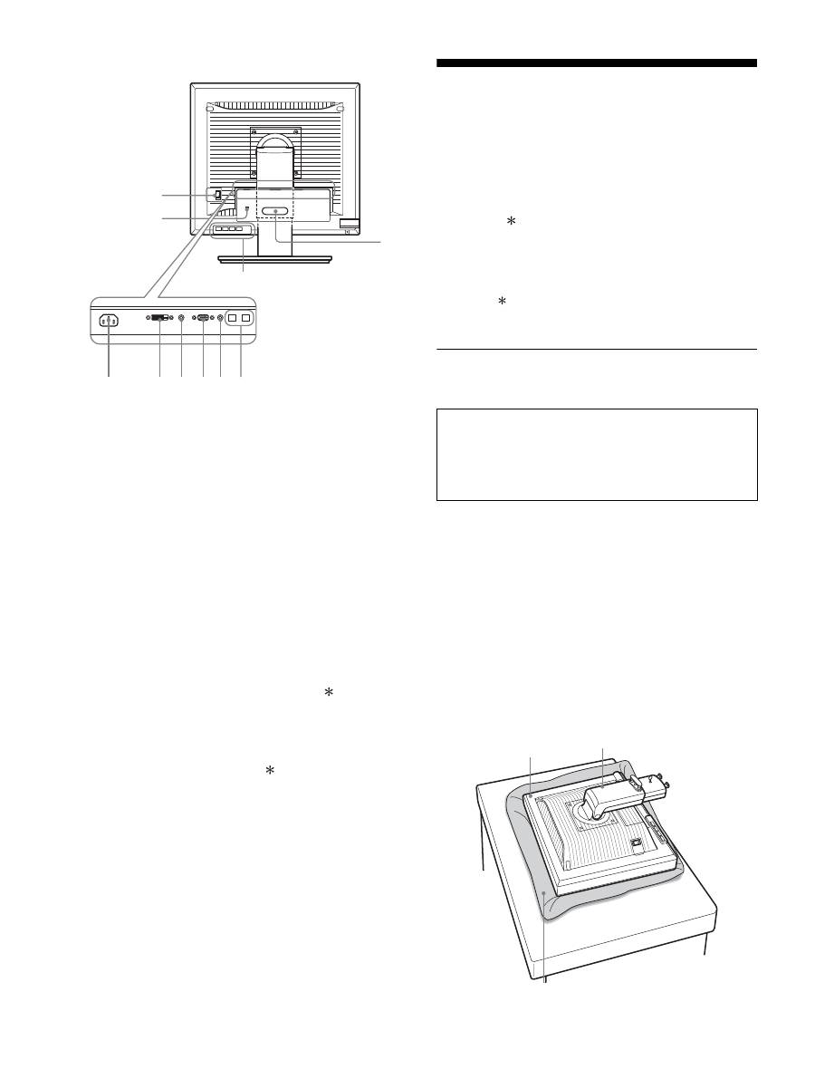
6
Rückseite des Bildschirms
8
Hauptnetzschalter MAIN POWER (Seite 10)
Mit diesem Schalter schalten Sie die Hauptstromversorgung
(MAIN POWER) des Bildschirms ein bzw. aus.
9
Netzeingang AC IN (Seite 9)
Mit diesem Anschluss verbinden Sie das Netzkabel
(mitgeliefert).
0
DVI-D-Eingangsanschluss (digitales RGB) (Seite 8)
An diesem Anschluss werden digitale RGB-Videosignale
eingespeist, die DVI Rev. 1.0 entsprechen.
qa
HD15-Eingang (analoges RGB) (Seite 8)
Dieser Anschluss dient zum Einspeisen von analogen RGB-
Videosignalen (0,700 Vp-p, positiv) und
Synchronisationssignalen.
qs
Kabelhalter (Seite 9)
Mit diesem Halter können Sie Kabel sicher am Bildschirm
befestigen.
qd
USB-Anschluss für nachgeschaltete Geräte (nur bei
Modellen mit USB-Anschluss) (Seite 8)
Wenn Sie eine USB-Maus, eine USB-Tastatur und zwei
Computer an den Monitor anschließen, können Sie zwischen
den Eingangssignalen von den beiden Computern wechseln.
qf
USB-Anschluss für vorgeschaltete Geräte (nur
Modelle mit USB-Anschluss)
Schließen Sie das USB-Kabel an den Computer und den
Bildschirm an.
qg
Diebstahlschutzbohrung
Die Diebstahlschutzbohrung ist für ein Micro Saver Security
System von Kensington gedacht.
Micro Saver Security System ist ein Markenzeichen von
Kensington.
qh
Audiobuchse für INPUT1
Diese Buchse kann für die Eingabe des Tonsignals mit der
Audioausgangsbuchse eines an INPUT1 angeschlossenen
Computers bzw. Audiogeräts verbunden werden.
qj
Audiobuchse für INPUT2
Diese Buchse kann für die Eingabe des Tonsignals mit der
Audioausgangsbuchse eines an INPUT2 angeschlossenen
Computers bzw. Audiogeräts verbunden werden.
Installation
Bevor Sie mit dem Bildschirm arbeiten, überprüfen Sie bitte, ob
folgende Teile mitgeliefert wurden:
• LCD-Bildschirm
• Netzkabel
• Ständerfuß
• HD15-HD15-Videosignalkabel (analoges RGB)
• DVI-D-Videosignalkabel (digitales RGB)
• Audiokabel (Stereo-Ministecker)
• USB-Kabel
• CD-ROM (Dienstprogramm für Windows/Macintosh,
Bedienungsanleitung usw.)
• Garantiekarte
• Kurzreferenz
Bei den mit gekennzeichneten Merkmalen gibt es hinsichtlich
der Spezifikationen Unterschiede zwischen den Modellen.
Näheres dazu finden Sie unter „Technische Daten“ (Seite 24).
Schritt 1: Zusammenbauen des
Ständers
x
Wenn Sie den mitgelieferten Ständer
verwenden
1
Öffnen Sie den Karton und nehmen Sie den
Ständerfuß heraus.
2
Überprüfen Sie, ob die aufgelisteten Teile
mitgeliefert wurden.
• An der Unterseite des Ständerfußes ist eine Schraube angebracht.
3
Legen Sie eine weiche Decke o. ä. auf einen
Schreibtisch oder eine ähnliche Ablagefläche.
Der LCD-Bildschirm und die Bildschirmoberfläche können
beschädigt werden, wenn Sie den Bildschirm ohne Unterlage
auf den Schreibtisch legen.
4
Nehmen Sie den Bildschirm aus dem Karton und
legen Sie ihn auf den Schreibtisch. Richten Sie
dabei den Rahmen des Bildschirms an der
Tischkante aus.
qg
qs
qd
8
9
q; qh qaqj qf
Drücken Sie nicht auf den LCD-Bildschirm, wenn Sie
den Bildschirm auf einen Schreibtisch oder eine
ähnliche Ablagefläche legen oder darauf aufstellen.
Andernfalls könnte die Gleichmäßigkeit des Bildes
auf dem Bildschirm beeinträchtigt oder der LCD-
Bildschirm beschädigt werden.
Bildschirm
Ständer
Weiche Unterlage
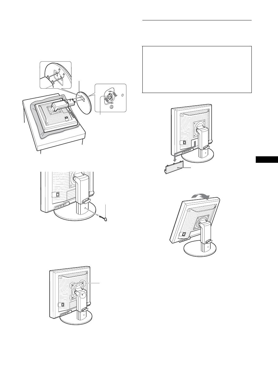
7
DE
5
Hängen Sie zum Anbringen des Ständerfußes die
Aussparungen am Ständerfuß in die Vorsprünge am
Ständer ein.
1
Heben Sie den Griff der Schraube an und schrauben
Sie den Ständerfuß gut fest.
2
Achten Sie darauf, dass die Schraube gut fixiert ist
und bringen Sie den Schraubengriff in die
Ausgangsposition.
6
Entfernen Sie den Anschlagstift, nachdem Sie den
höhenverstellbaren Ständer aufgestellt haben.
Hinweis
Entfernen Sie den Anschlagstift nicht, während der Ständer waagrecht
liegt. Der Ständerfuß könnte sonst herausrutschen, herunterfallen und
Verletzungen verursachen.
x
Wenn Sie den VESA-Ständer verwenden
Sie können den am Bildschirm montierten mitgelieferten Ständer
abnehmen und einen VESA-Ständer eines anderen Herstellers
anbringen.
Schritt 2: Anschließen der
Videosignalkabel
1
Schieben Sie die Anschlussabdeckung nach unten.
2
Neigen Sie den Bildschirm nach oben.
Und stellen Sie den Bildschirmwinkel größer ein.
1
Ständerfuß
2
Schraube
Anschlagstift
Mit VESA-
Ständer
kompatible
Schrauben (4)
• Schalten Sie vor dem Anschließen den Bildschirm und
den Computer aus.
Hinweise
• Berühren Sie die Stifte des Videosignalkabelanschlusses nicht. Sie
könnten die Stifte sonst möglicherweise verbiegen.
• Achten Sie darauf, den Stecker des Videosignalkabels korrekt am
Anschluss auszurichten, damit die Stifte am Stecker des
Videosignalkabels nicht verbogen werden.
Anschlussabdeckung
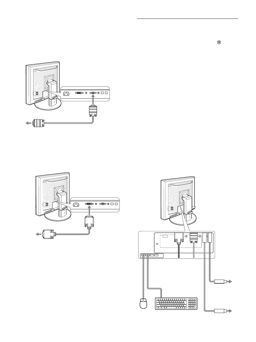
8
3
Schließen Sie die Videosignalkabel an den
Bildschirm an.
x
Anschließen eines Computers mit einem
HD15-Ausgangsanschluss (analoges RGB)
Schließen Sie den Computer mit dem mitgelieferten HD15-
HD15-Videosignalkabel (analoges RGB) an den HD15-
Eingangsanschluss (analoges RGB) am Bildschirm an.
x
Anschließen eines Computers mit einem
DVI-Ausgangsanschluss (digitales RGB)
Schließen Sie den Computer mit dem mitgelieferten DVI-D-
Videosignalkabel (digitales RGB) an den DVI-D-
Eingangsanschluss (digitales RGB) am Bildschirm an.
Schritt 3: Anschließen von USB-Maus,
USB-Tastatur oder anderen
Geräten (nur bei Modellen
mit USB-Anschluss)
Wenn Sie eine USB-Maus, eine USB-Tastatur oder andere Geräte
anschließen, können Sie zwischen den Eingängen wechseln (KVM-
Funktion).
Einzelheiten dazu finden Sie unter „Die KVM-Funktion“ (Seite 19).
Wenn Sie den Bildschirm ohne USB-Maus, USB-Tastatur und
andere Geräte verwenden, fahren Sie mit Schritt 4 fort.
1
Verbinden Sie den Bildschirm und den Computer
mit dem mitgelieferten Kabel.
2
Schließen Sie die USB-Maus, die USB-Tastatur oder
andere Geräte an den Bildschirm an.
Für Macintosh:
Wenn Sie eine Macintosh-Tastatur mit Netztaste an den USB-
Anschluss für nachgeschaltete Geräte anschließen,
funktioniert die Netztaste an der Tastatur unter Umständen
nicht. Benutzen Sie zum Einschalten entweder die Netztaste
am Computer oder verbinden Sie die Tastatur direkt mit dem
Computer, schalten Sie diesen ein und verbinden Sie dann den
USB-Anschluss für nachgeschaltete Geräte mit der Tastatur.
Hinweise
• Der USB-Anschluss dieses Bildschirms ist mit Windows 2000/Windows
XP Professional/Windows XP Home Edition und Macintosh kompatibel.
• Wenn an den Computer bereits eine USB-Maus, eine USB-Tastatur
oder andere Geräte angeschlossen sind, lösen Sie die USB-Maus, die
USB-Tastatur bzw. die anderen Geräte und schließen Sie sie erneut an.
• Diese Konfiguration ist ausschließlich für USB-kompatible Computer
und Betriebssysteme gedacht. Weitere Erläuterungen finden Sie in der
Bedienungsanleitung zum Computer oder Betriebssystem.
an den HD15-Ausgangsanschluss
(analoges RGB) des Computers
HD15-HD15-Videosignalkabel
(analoges RGB) (mitgeliefert)
an den HD15-
Eingangsanschluss
(analoges RGB)
an den DVI-Ausgangsanschluss
(digitales RGB) des Computers
DVI-D-Videosignalkabel
(digitales RGB) (mitgeliefert)
an den DVI-D-
Eingangsanschluss
(digitales RGB)
AC IN
DVI-D
HD15
1
2
2
1
an USB-Anschluss
am Computer
an USB-Anschluss
am Computer
USB-Kabel
(mitgeliefert)
USB-Kabel (mitgeliefert)
USB-Maus
USB-
Tastatur
2
2
1
1
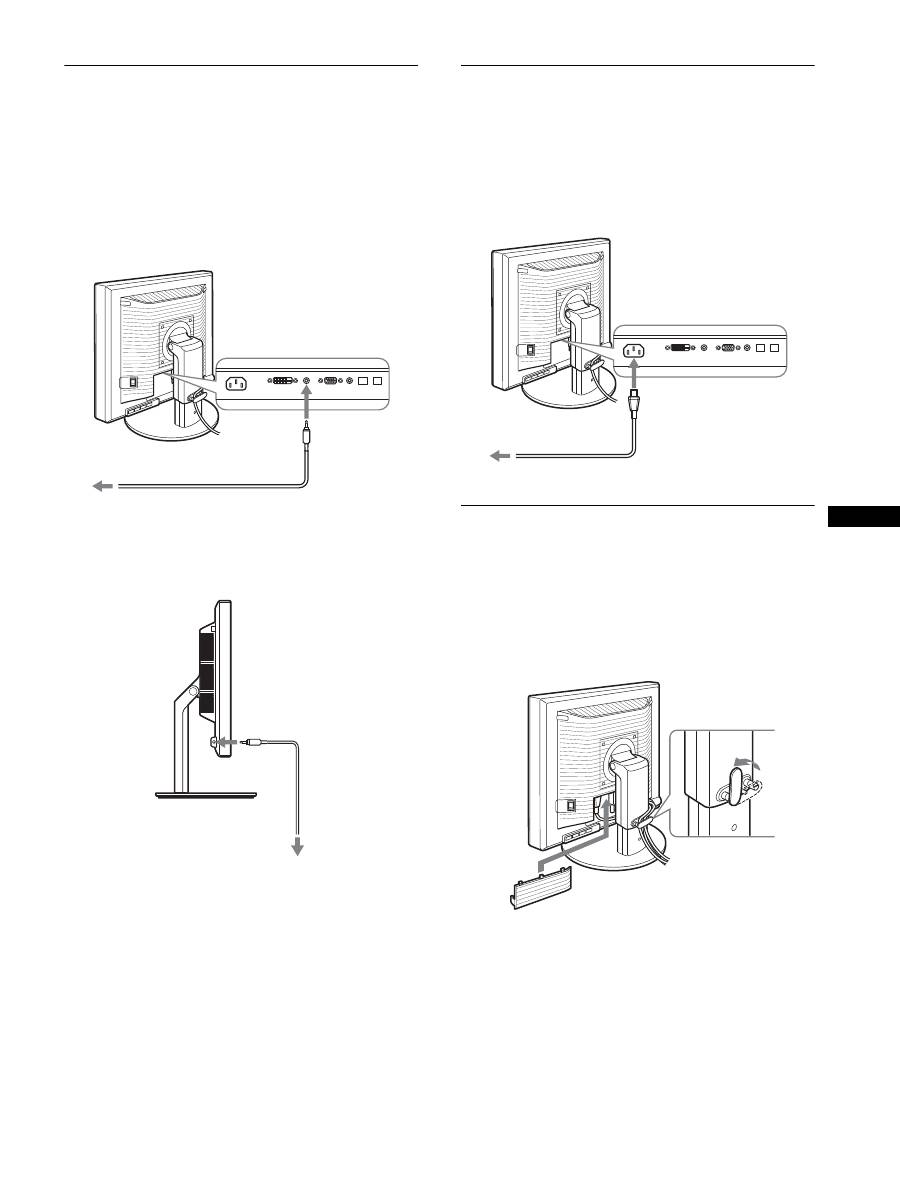
9
DE
Schritt 4: Anschließen der
Audiokabel
Wenn kein Ton ausgegeben werden soll, ist diese
Verbindung nicht erforderlich.
1
Verbinden Sie die Audioeingangsbuchse am
Bildschirm über das mitgelieferte Audiokabel mit
der Audioausgangsbuchse am Computer oder an
einem anderen Audiogerät.
2
Schließen Sie ein Audiokabel (nicht mitgeliefert)
fest an die Audioausgangsbuchse am Bildschirm
an.
Die Audioausgabe ändert sich, wenn der Audioeingangs- und
Audioausgangsanschluss des Bildschirms angeschlossen wurden.
Schließen Sie Audiogeräte an, die den in den
Audioeingangsspezifikationen des Bildschirms angegebenen
Eingangswerten entsprechen. Wenn der Eingang zu hoch ist, kann
der Bildschirm beschädigt werden.
Schritt 5: Anschließen des
Netzkabels
1
Schließen Sie das mitgelieferte Netzkabel fest an
den Netzeingang AC IN des Bildschirms an.
2
Schließen Sie das andere Ende fest an eine
Netzsteckdose an.
Schritt 6: Befestigen der Kabel und
Schließen der
Anschlussabdeckung
1
Führen Sie die Kabel durch den Kabelhalter, wie auf
der Abbildung zu sehen.
2
Schließen Sie die Anschlussabdeckung.
Hinweis
Achten Sie beim Bündeln der Kabel darauf, dass diese noch etwas Spiel
haben. Andernfalls lösen sie sich möglicherweise von den Anschlüssen
bzw. Steckern, wenn Sie den Bildschirmwinkel einstellen. Wenn Sie die
Kabel zu straff ziehen, können sie beschädigt werden.
an den Audioausgang des
Computers oder eines anderen
Audiogeräts
Audiokabel (mitgeliefert)
an den
Audioeingang
Audiokabel
(nicht mitgeliefert)
an den Audioausgang
2
an Netzsteckdose
Netzkabel (mitgeliefert)
1
an AC IN
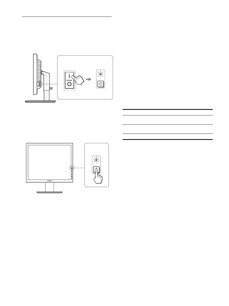
10
Schritt 7: Einschalten von
Bildschirm und Computer
1
Vergewissern Sie sich, dass die Netzanzeige
1
rot
blinkt. Bei Lieferung ist der Hauptnetzschalter MAIN
POWER auf
\
eingestellt.
Hinweis
Wenn der Hauptnetzschalter MAIN POWER an der rechten Seite
des Bildschirms nicht auf
\
steht, drücken Sie die Seite
\
.
Vergewissern Sie sich, dass die Netzanzeige
1
rot blinkt.
2
Drücken Sie den Netzschalter
1
vorne rechts am
Bildschirm.
Die Netzanzeige
1
leuchtet grün auf.
3
Schalten Sie den Computer ein.
Wenn auf dem Bildschirm kein Bild erscheint
• Das Netzkabel und die Videosignalkabel müssen richtig
angeschlossen sein.
• Wenn „KEIN EING SIGNAL“ auf dem Bildschirm
erscheint:
– Der Computer befindet sich im Stromsparmodus. Drücken Sie
eine beliebige Taste auf der Computertastatur oder bewegen
Sie die Maus.
– Vergewissern Sie sich, dass das Eingangssignal korrekt
eingestellt ist, indem Sie die Taste OK drücken (Seite 12).
• Wenn „KABEL NICHT VERBUNDEN“ auf dem Bildschirm
erscheint:
– Überprüfen Sie, ob die Videosignalkabel richtig angeschlossen
sind.
– Vergewissern Sie sich, dass das Eingangssignal korrekt
eingestellt ist, indem Sie die Taste OK drücken (Seite 12).
• Wenn „UNZULÄSSIGER BEREICH“ erscheint:
Schließen Sie wieder Ihren alten Bildschirm an. Stellen Sie
dann die Grafikkarte des Computers auf folgende Werte ein.
Schlagen Sie bitte unter den weiteren Informationen über
Bildschirmmeldungen nach (siehe „Fehlersymptome und
Abhilfemaßnahmen“ auf Seite 21).
Spezielle Treiber werden nicht benötigt
Dieser Monitor entspricht dem Plug-and-Play-Standard „DDC“, so dass
alle Daten des Monitors automatisch erkannt werden. Daher muss kein
spezifischer Treiber auf dem Computer installiert werden.
Wenn Sie den Monitor an den Computer anschließen und diesen dann
zum ersten Mal starten, wird möglicherweise der Hardware-Assistent auf
dem Bildschirm angezeigt. Gehen Sie in diesem Fall nach den
Anweisungen auf dem Bildschirm vor. Der Plug-and-Play-Monitor ist
automatisch ausgewählt, so dass Sie ohne weitere Vorbereitungen mit
diesem Monitor arbeiten können.
Die Vertikalfrequenz wechselt zu 60 Hz.
Da das Flimmern auf dem Monitor fast nicht sichtbar ist, können Sie die
Einstellung unverändert lassen. Sie brauchen die Vertikalfrequenz nicht
auf einen besonders hohen Wert einzustellen.
MAIN POWER
leuchtet rot
leuchtet grün
Analoges RGB
Digitales RGB
Horizontal-
frequenz
28–92 kHz
28–75 kHz
Vertikal-
frequenz
48–85 Hz
60 Hz
Auflösung
1.600
×
1.200 oder weniger
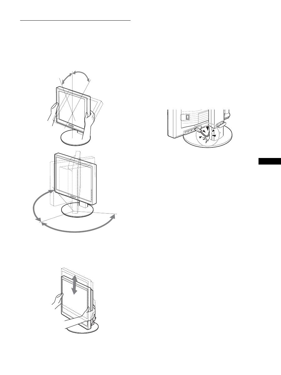
11
DE
Schritt 8: Einstellung von Neigung
und Höhe
Mit dem Ständer können Sie den Bildschirm innerhalb der unten
abgebildeten Winkel nach Bedarf einstellen.
Fassen Sie den LCD-Bildschirm an beiden Seiten und
stellen Sie den Bildschirm wie gewünscht ein.
Wenn Sie den höhenverstellbaren Ständer verwenden, können Sie
wie unten dargestellt auch die Höhe des Bildschirms einstellen.
Fassen Sie den LCD-Bildschirm an beiden Seiten
und stellen Sie ihn auf die gewünschte Höhe ein.
So können Sie ergonomisch mit dem Bildschirm
arbeiten
Berücksichtigen Sie beim Einstellen des Bildschirmwinkels die
Höhe von Schreibtisch und Stuhl und achten Sie darauf, dass auf
dem Bildschirm keine Lichtreflexe auftreten.
Hinweise
• Stoßen Sie den Bildschirm, die Kabel und andere USB-Geräte beim
Einstellen der Bildschirmposition nicht gegen irgendwelche
Gegenstände. Bewegen Sie den Bildschirm vorsichtig.
• Achten Sie darauf, dass keine Gegenstände unter dem Bildschirm
liegen, wenn Sie die Höhe des Ständers einstellen. Andernfalls kann
der Bildschirm beschädigt werden.
• Achten Sie beim Anschließen von USB-Produkten oder USB-Geräten
an den Bildschirm darauf, diese nicht gegen den Ständerfuß zu stoßen.
Beim Einstellen von Neigung und Höhe des Bildschirms kann dieser je
nach Größe der Produkte bzw. Geräte beschädigt werden. (nur bei
Modellen mit USB-Anschluss)
ca. 20°
ca. 5°
ca. 175°
ca. 175°
Höhenverstellbarer
Ständer
ca. 110 mm
Drehständer
ca. 130 mm
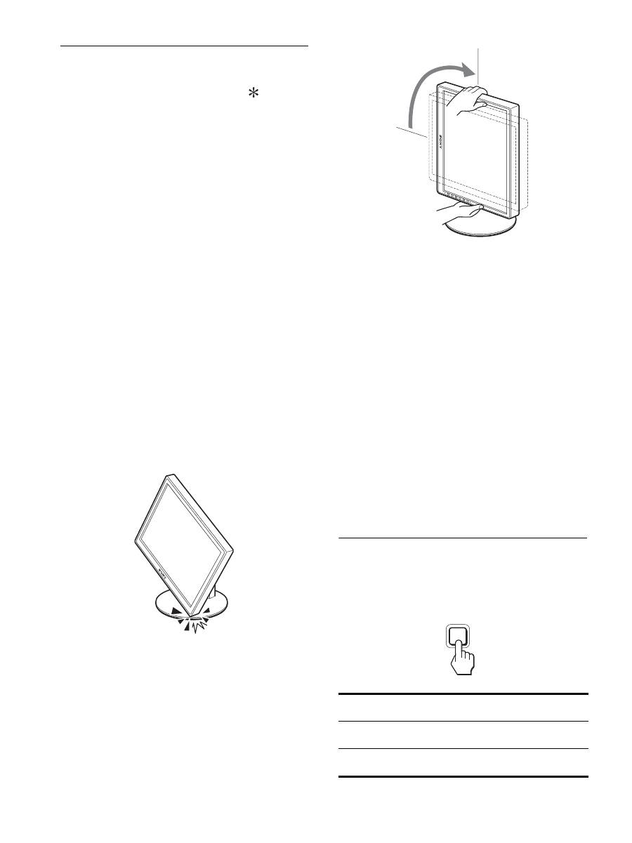
12
Umschalten des Bildes zwischen
Hoch- und Querformat (nur bei
Modellen mit Drehständer)
Wenn Ihr Computer über eine Funktion verfügt, mit der die
Anzeige auf dem Bildschirm zwischen Hoch- und Querformat
umgeschaltet werden kann, können Sie den Bildschirm um 90°
drehen.
Stellen Sie das Umschalten des Formats zunächst am Computer
ein und drehen Sie dann den Bildschirm.
Drehen des Bildschirms ins Hochformat
1
Stellen Sie zunächst am Computer das Drehen des
Bildschirms um 90° gegen den Uhrzeigersinn ein.
2
Drücken Sie die Taste MENU am Bildschirm, wählen
Sie „MENÜ DREHEN“ aus dem Menü OPTIONEN
und wählen Sie „HOCHFORMAT“.
Sie können die Position des Menüs auf dem Bildschirm je
nach Anzeigeformat ändern.
3
Halten Sie den Bildschirm an beiden Seiten fest und
bringen Sie ihn vorsichtig in die höchste Position.
Hinweise
• Wenn der Bildschirm an ein USB-Gerät oder an USB-kompatible
Produkte angeschlossen ist und Sie den Bildschirm drehen, kann er
beschädigt werden.
• Stoßen Sie den Bildschirm, die Kabel und andere USB-Geräte
beim Drehen des Bildschirms nicht gegen irgendwelche
Gegenstände. Bewegen Sie den Bildschirm vorsichtig.
• Wenn Sie den Bildschirm drehen wollen, entfernen Sie alle Kabel
aus dem Kabelhalter, verschieben Sie sie vorsichtig und ziehen Sie
nicht zu fest daran.
4
Halten Sie den Bildschirm an beiden Seiten fest und
drehen Sie ihn langsam um 90° im Uhrzeigersinn.
Weiter als um 90° können Sie den Bildschirm nicht drehen.
5
Halten Sie den Bildschirm an beiden Seiten fest und
stellen Sie Höhe und Neigung ein.
So bringen Sie den Bildschirm zurück in die
ursprüngliche Position
1
Stellen Sie zunächst am Computer das Drehen des
Bildschirms um 90° im Uhrzeigersinn ein.
2
Drücken Sie die Taste MENU am Bildschirm, wählen
Sie „MENÜ DREHEN“ aus dem Menü OPTIONEN
und wählen Sie „QUERFORMAT“.
Bringen Sie das Menü auf dem Bildschirm nun wieder zurück
in die ursprüngliche Position.
3
Halten Sie den Bildschirm an beiden Seiten fest und
bringen Sie ihn vorsichtig in die höchste Position.
4
Halten Sie den Bildschirm an beiden Seiten fest und
drehen Sie ihn langsam um 90° gegen den
Uhrzeigersinn.
Auswählen des Eingangssignals
(INPUT1/INPUT2)
Drücken Sie die Taste OK.
Das Eingangssignal wechselt mit jedem Tastendruck auf OK.
Bildschirmmeldung (erscheint
ca. 5 Sekunden lang oben links)
Konfiguration des
Eingangssignals
EINGANG1 : DVI-D
DVI-D-Eingangsanschluss
(digitales RGB) für INPUT1
EINGANG2 : HD15
HD15-Eingangsanschluss
(analoges RGB) für INPUT2
INPUT
OK
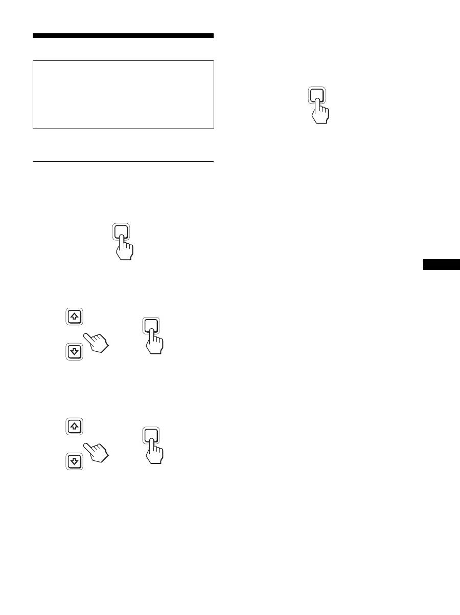
13
DE
Einstellen des Bildschirms
Mit den Bildschirmmenüs können Sie eine Vielzahl von
Einstellungen vornehmen.
Navigieren in den Menüs
1
Rufen Sie das Hauptmenü auf.
Drücken Sie die Taste MENU, um das Hauptmenü auf dem
Bildschirm aufzurufen.
2
Wählen Sie das Menü aus, in dem Sie Einstellungen
vornehmen wollen.
Wählen Sie mit den Tasten
m
/
M
das gewünschte Menü aus.
Wählen Sie mit der Taste OK die gewünschte Menüoption aus.
3
Wählen Sie einen Wert für die Option.
Nehmen Sie die Einstellung mit den Tasten
m
/
M
vor und
drücken Sie dann die Taste OK.
Sobald Sie die Taste OK drücken, wird die Einstellung
gespeichert und das vorherige Menü wird wieder angezeigt.
4
Schließen Sie das Menü.
Wenn Sie die Taste MENU einmal drücken, erscheint wieder
die normale Anzeige. Wenn Sie keine weitere Taste drücken,
wird das Bildschirmmenü nach etwa 45 Sekunden
automatisch ausgeblendet.
x
Zurücksetzen der Werte auf die
Standardeinstellungen
Sie können die Einstellungen über das Menü ZURÜCKSETZEN
zurücksetzen. Weitere Informationen zum Zurücksetzen der
Einstellungen finden Sie unter
0
(ZURÜCKSETZEN) auf
Seite 17.
Vor dem Einstellen
Verbinden Sie den Bildschirm mit dem Computer und schalten
Sie beide Geräte ein.
Die besten Ergebnisse erzielen Sie, wenn Sie nach dem
Anschließen des Bildschirms an den Computer und dem
Einschalten des Geräts mindestens 30 Minuten warten, bevor
Sie irgendwelche Einstellungen vornehmen.
MENU
INPUT
OK
,
INPUT
OK
,
MENU

14
Liste der Menüoptionen
1)
Wenn der ECO-Modus auf „AUTOMATISCH“ gesetzt ist, können Sie
HINTERGRUNDBEL nicht einstellen.
2)
KONTRAST, HELLIGKEIT und GAMMA können nicht eingestellt
werden, wenn „sRGB“ ausgewählt ist.
SDM-S205F
Menü BILD EINSTELLEN
MODUS (ECO-Modus)
HELL
MITTEL
DUNKEL
AUTOMATISCH
1)
HINTERGRUNDBEL
;
1)
6
KONTRAST
;
1) 2)
8
HELLIGKEIT
;
2)
GAMMA
BENUTZER
2)
CAL.
2)
FARBE
9300K
6500K
sRGB
2)
BENUTZER
(GAIN und BIAS)
SMOOTHING
TEXT
STANDARD
GRAFIK
0
MODUS ZURÜCK
;
BILDSCHIRM
AUTOMATISCH
PHASE
PITCH
H CENTER
V CENTER
ZOOM
FULL
FORMAT GLEICH
ORIGINAL
POSITION MENÜ
;
EINGANGSERKENN
AUTOMATIK EIN
EINGANG1
EINGANG2
AUTOMATIK AUS
LANGUAGE
ENGLISH
FRANÇAIS
DEUTSCH
ESPAÑOL
ITALIANO
NEDERLANDS
SVENSKA
0
ZURÜCKSETZEN
OK
ABBRECHEN
MENÜ-SPERRE
EIN
AUS
SDM-S205K
Menü BILD EINSTELLEN
MODUS (ECO-Modus)
HELL
MITTEL
DUNKEL
AUTOMATISCH
1)
HINTERGRUNDBEL
;
1)
6
KONTRAST
;
1) 2)
8
HELLIGKEIT
;
2)
GAMMA
BENUTZER
2)
CAL.
2)
FARBE
9300K
6500K
sRGB
2)
BENUTZER
(GAIN und BIAS)
SMOOTHING
TEXT
STANDARD
GRAFIK
0
MODUS ZURÜCK
;
BILDSCHIRM
AUTOMATISCH
PHASE
PITCH
H CENTER
V CENTER
ZOOM
FULL
FORMAT GLEICH
ORIGINAL
POSITION MENÜ
;
EINGANGSERKENN
AUTOMATIK EIN
EINGANG1
EINGANG2
AUTOMATIK AUS
LANGUAGE
ENGLISH
FRANÇAIS
DEUTSCH
ESPAÑOL
ITALIANO
NEDERLANDS
SVENSKA
0
ZURÜCKSETZEN
OK
ABBRECHEN
MENÜ-SPERRE
EIN
AUS
OPTIONEN
MENÜ DREHEN
QUERFORMAT
HOCHFORMAT
15
DE
Menü BILD EINSTELLEN
Hinweise
• Wenn der ECO-Modus auf „AUTOMATISCH“ gesetzt ist, können Sie
HINTERGRUNDBEL nicht einstellen.
• Wenn Sie „sRGB“ auswählen, lassen sich KONTRAST und
HELLIGKEIT nicht einstellen.
Hinweis
Wenn Sie „sRGB“ auswählen, lässt sich GAMMA nicht einstellen.
1)
Ist ein Computer oder ein anderes Gerät, den/das Sie an den Bildschirm
anschließen, nicht sRGB-konform, können Sie die Farben nicht auf das
sRGB-Profil einstellen.
Wenn Sie „sRGB“ auswählen, lassen sich KONTRAST,
HELLIGKEIT und GAMMA nicht einstellen.
Wenn Sie den ECO-Modus auf „AUTOMATISCH“ gesetzt haben,
können Sie „sRGB“ nicht auswählen.
Hinweis
Bei einer Auflösung des Bildsignals von 1.600 × 1.200 steht die Funktion
SMOOTHING nicht zur Verfügung.
Menü BILDSCHIRM (nur bei
analogem RGB-Signal)
x
Automatische Einstellung der Bildqualität
Wenn am Bildschirm ein Eingangssignal eingeht,
werden automatisch die Bildposition und die Schärfe
(Phase/Pitch) eingestellt. So ist gewährleistet, dass das
Bild auf dem Bildschirm scharf und in guter Qualität
angezeigt wird (Seite 19).
Hinweis
Wenn die automatische Einstellung der Bildqualität aktiviert ist,
funktioniert nur noch der Netzschalter
1
.
Wenn das Bild mit der automatischen Einstellung der
Bildqualität dieses Bildschirms nicht gut genug
eingestellt wird
Sie können eine weitere automatische Einstellung der Bildqualität
für das aktuelle Eingangssignal vornehmen. Näheres dazu finden
Sie unter AUTOMATISCH weiter unten.
Wenn Sie darüber hinaus weitere Feineinstellungen der
Bildqualität vornehmen müssen
Sie können die Schärfe (PHASE/PITCH) und die Position
(horizontal/vertikal) des Bildes auch manuell einstellen.
Diese Einstellungen werden automatisch im Speicher
festgehalten und wieder abgerufen, wenn dasselbe
Eingangssignal erneut am Bildschirm eingeht. Eine
Neueinstellung kann erforderlich werden, wenn Sie nach dem
erneuten Anschluss des Computers das Eingangssignal ändern.
Optionen
Taste
M
Taste
m
MODUS
Stellen Sie den ECO-Modus ein.
Wählen Sie für die Helligkeit des
Bildschirms HELL, MITTEL, DUNKEL
oder AUTOMATISCH, um Energie zu
sparen.
Sie können einen Eingang festlegen und
verschiedene Modi einstellen.
HELL
MITTEL
DUNKEL
AUTOMATISCH
HINTERGRUNDBEL
Der Bildschirm
wird heller.
Der Bildschirm
wird dunkler.
6
KONTRAST
Der Bildkontrast
wird schärfer.
Der Bildkontrast
wird weicher.
8
HELLIGKEIT
Das Bild wird heller
(Schwarzwert).
Das Bild wird dunkler
(Schwarzwert).
Optionen
GAMMA
Optionen
Funktionen
BENUTZER
Sie können die Bildfarben selbst einstellen.
CAL.
Mit diesem Modus wird am LCD-
Bildschirm der ursprüngliche
Gammawert eingestellt. Stellen Sie
diesen Modus ein, wenn Sie für optimale
Kalibrierergebnisse ein externes
Farbkalibrierungssystem verwenden.
Optionen
FARBE
Optionen
Funktionen
9300K
Die Blaukomponente wird verstärkt.
6500K
Die Rotkomponente wird verstärkt.
sRGB
1)
Wenn Sie „sRGB“ wählen, werden die
Farben an das sRGB-Profil angepasst.Die
sRGB-Farbeinstellung beruht auf einem
Farbraumprotokoll nach
Industriestandard für Computer-Produkte.
Wenn Sie „sRGB“ wählen, muss als
Farbeinstellung für den Computer das
sRGB-Profil ausgewählt sein.
BENUTZER
Sie können weitere Einstellungen für
hellere Bereiche (GAIN: Weißwert) und
dunklere Bereiche (BIAS: Schwarzwert)
vornehmen. Außerdem können Sie die
Farbeinstellungen speichern.
Optionen
SMOOTHING
Optionen
Funktionen
TEXT
Zeichen werden mit scharfen Konturen
angezeigt. Dieser Modus eignet sich für
textorientierte Anwendungen.
STANDARD
Standardglättungseffekt.
GRAFIK
Bilder werden in guter Qualität
angezeigt. Dieser Modus eignet sich für
Fotos und sonstige Bilder.
Optionen
0
MODUS ZURÜCK
Optionen
Funktionen
OK
Sie können HINTERGRUNDBEL,
KONTRAST, HELLIGKEIT,
GAMMA und FARBE auf die
Standardwerte zurücksetzen.
ABBRECHEN
Das Zurücksetzen wird abgebrochen
und das Menü wird wieder angezeigt.
16
x
Manuelles Einstellen der Bildschärfe und
-position (PHASE/PITCH/H CENTER/V CENTER)
Sie können Bildschärfe und -position folgendermaßen einstellen.
1
Stellen Sie am Computer die Auflösung auf 1.600 ×
1.200 ein.
2
Legen Sie die CD-ROM ein.
3
Starten Sie die CD-ROM und rufen Sie das
Testmuster auf.
Für Windows-Benutzer
Wenn die Auto-Run-Funktion eingeschaltet ist:
1
Klicken Sie auf „Display Einstellung (UTILITY)“.
2
Klicken Sie auf „Adjust“, um die Auflösung zu
überprüfen, und klicken Sie dann auf „Next“.
Die Testmuster für PITCH, PHASE, H CENTER und V
CENTER erscheinen nacheinander.
Wenn die Auto-Run-Funktion versagt:
1
Öffnen Sie „Arbeitsplatz“ und klicken Sie mit der rechten
Maustaste auf das CD-ROM-Symbol. Gehen Sie zu
„Explorer“ und öffnen Sie das CD-ROM-Symbol.
2
Öffnen Sie [Utility] und wählen Sie dann [Windows].
3
Starten Sie [Win_Utility.exe].
Das Testmuster erscheint.
Für Macintosh-Benutzer
1
Öffnen Sie [Utility] und wählen Sie dann [Mac].
2
Starten Sie [Mac_Utility.exe].
Das Testmuster erscheint.
Menü ZOOM
Hinweis
Bei einer Auflösung des Bildsignals von 1.600 × 1.200 steht diese
Funktion nicht zur Verfügung. Das Bild wird auf dem Bildschirm als
Vollbild angezeigt.
Menü POSITION MENÜ
Optionen
Funktionen
AUTOMATISCH
Hiermit nehmen Sie für das aktuelle
Eingangssignal die geeigneten
Einstellungen für Phase und Pitch des
Bildschirms sowie für die horizontale
bzw. vertikale Position vor und speichern
die Einstellungen.
Optionen
Tasten
m
/
M
PHASE
Minimiert Horizontalstreifen auf dem
Bildschirm.
PITCH
Eliminiert Vertikalstreifen auf dem
Bildschirm.
H CENTER
Dient zum Korrigieren der Bildposition,
wenn das Bild nicht in der Mitte des
Bildschirms angezeigt wird.
V CENTER
Optionen
Funktionen
FULL
Das Eingangssignal wird in voller Größe
auf dem Bildschirm angezeigt,
unabhängig von dem Modus oder der
Auflösung des Bildes.
FORMAT GLEICH
Das Eingangssignal wird im
tatsächlichen Bildseitenverhältnis auf
dem Bildschirm angezeigt. Daher
können je nach Signal schwarze Streifen
oben und unten am Bildrand erscheinen.
ORIGINAL
Das Eingangssignal wird mit der
tatsächlichen Auflösung auf dem
Bildschirm angezeigt. Signale mit einer
niedrigeren Auflösung als 1.600 × 1.200
werden in der Bildschirmmitte und
umgeben von einem schwarzen Rahmen
angezeigt.
Optionen
Tasten
m
/
M
POSITION MENÜ
Sie können die Position des Menüs auf
dem Bildschirm ändern. Dabei haben Sie
die Wahl zwischen 9 Positionen.
17
DE
Menü EINGANGSERKENN
Sie können nach allen Eingangssignalen suchen und automatisch
zwischen den Signalen umschalten.
Menü LANGUAGE
0
Menü ZURÜCKSETZEN (zum
Zurücksetzen auf die
Standardeinstellungen)
Menü MENÜ-SPERRE
Menü OPTIONEN
Optionen
Funktionen
AUTOMATIK EIN
Wenn am ausgewählten Eingang kein
Signal eingeht oder wenn Sie mit der
Taste OK einen Eingang auswählen, an
dem kein Signal eingeht, erscheint eine
Bildschirmmeldung (Seite 20). Dann
prüft der Bildschirm, ob ein anderes
Eingangssignal vorhanden ist, und
schaltet automatisch zu dem
betreffenden Eingang um.
Wenn zu einem anderen Eingang
umgeschaltet wird, erscheint der ausgewählte
Eingang oben links auf dem Bildschirm.
Wenn auch an diesem Eingang keine
Signale eingespeist werden, wechselt der
Bildschirm in den Energiesparmodus.
EINGANG1
Beim Einschalten des Bildschirms wird
EINGANG1 oder EINGANG 2 als
vorrangige Einstellung angezeigt
(EINGANGSERKENN funktioniert
nicht).
EINGANG2
AUTOMATIK AUS
Der Eingang wird nicht automatisch
gewechselt. Drücken Sie die Taste OK,
wenn Sie den Eingang wechseln
möchten.
Optionen
Tasten
m
/
M
ENGLISH
FRANÇAIS
DEUTSCH
ESPAÑOL
ITALIANO
NEDERLANDS
SVENSKA
Englisch
Französisch
Spanisch
Italienisch
Niederländisch
Schwedisch
Russisch
Japanisch
Chinesisch
Optionen
Funktionen
OK
Alle Einstellungen werden auf die
Standardwerte zurückgesetzt, mit
Ausnahme der Einstellungen im Menü
(LANGUAGE).
ABBRECHEN
Das Zurücksetzen wird abgebrochen und
das Menü wird wieder angezeigt.
Optionen
Funktionen
EIN
Nur der Netzschalter
1
funktioniert.
Wenn Sie versuchen, eine andere
Funktion auszuführen, erscheint das
Symbol
(MENÜ-SPERRE) auf dem
Bildschirm.
AUS
Damit schalten Sie
(MENÜ-
SPERRE) aus. Wenn
(MENÜ-
SPERRE) eingeschaltet ist und Sie die
Taste MENU drücken, wird
(MENÜ-SPERRE) automatisch
ausgewählt.
Optionen
MENÜ DREHEN
Optionen
Funktionen
QUERFORMAT
Die Anzeige erscheint im Querformat.
HOCHFORMAT
Die Anzeige erscheint im Hochformat.
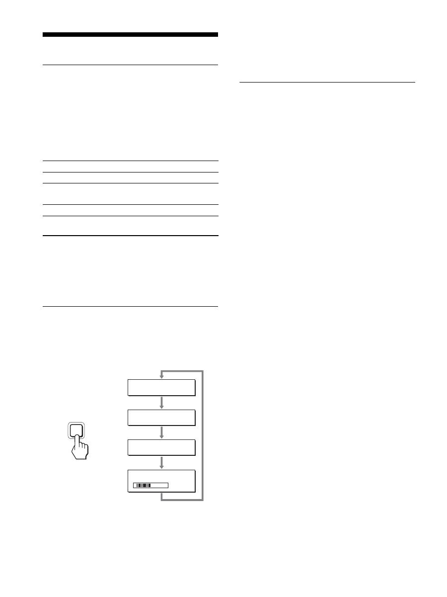
18
Technische Merkmale
Die Energiesparfunktion
Dieser Bildschirm erfüllt die Energiesparrichtlinien der VESA,
des
E
NERGY
S
TAR-Programms und des NUTEK-Standards.
Wenn der Bildschirm an einen Computer oder eine Grafikkarte
angeschlossen ist, der bzw. die DPMS-konform (Display Power
Management Standard) für Analogeingangssignale/DMPM-
konform (DVI Digital Monitor Power Management) für
Digitaleingangssignale ist, wird der Stromverbrauch des
Bildschirms wie unten erläutert reduziert.
1)
Wenn der Computer in den Modus „Deaktiviert“ wechselt, geht kein
Eingangssignal mehr ein und KEIN EING SIGNAL erscheint auf
dem Bildschirm. Nach 5 Sekunden schaltet der Bildschirm in den
Energiesparmodus.
„Tiefschlaf“ ist ein Energiesparmodus, der von der
EPA (Environmental Protection Agency - Umweltbehörde der USA)
definiert wurde.
Verringern der Leistungsaufnahme
(ECO-Modus)
Durch mehrmaliges Drücken der Taste ECO an der Vorderseite
des Bildschirms können Sie die Bildschirmhelligkeit auswählen.
Der Modus wird auf dem Bildschirm angezeigt und die
Bildhelligkeit wird je nach dem ausgewählten Modus eingestellt.
Nach etwa 5 Sekunden wird das Menü automatisch ausgeblendet.
Mit dem Wechsel des Modus von HELL zu MITTEL zu
DUNKEL wird der Bildschirm immer dunkler und die
Leistungsaufnahme immer geringer.
Standardmäßig ist die Bildschirmhelligkeit auf HELL eingestellt.
Automatische
Helligkeitseinstellung
(Lichtsensor)
Der Monitor kann die Helligkeit des Bildschirms automatisch auf
die Umgebungshelligkeit einstellen. Die Bildschirmhelligkeit
wird auf den geeignetsten Wert eingestellt, wenn Sie den ECO-
Modus mit der Taste ECO an der Vorderseite des Monitors auf
AUTOMATISCH stellen oder wenn Sie den Modus im Menü
BILD EINSTELLEN einstellen. Standardmäßig ist die
Bildschirmhelligkeit auf „HELL“ eingestellt. Wenn Sie den
ECO-Modus mit der Taste ECO vorn am Monitor auf
„AUTOMATISCH“ setzen, wird der Einstellbalken angezeigt.
Sie können die Helligkeit anhand des Balkens mit den Tasten
m
/
M
einstellen. Die Bildschirmhelligkeit ändert sich je nach dem
Pegel, den Sie hier einstellen.
Betriebsmodus
Netzanzeige
1
Normalbetrieb
grün
Deaktiviert
1)
(Tiefschlaf)
orange
Ausgeschaltet
rot
Hauptstromversorgung
ausgeschaltet
aus
5 0
E C O
H E L L
:
E C O
M I T T E L
:
E C O
D U N K E L
:
E C O
AU TO M AT I S C H
:
,
ECO
19
DE
Automatische Einstellung der
Bildqualität
(nur analoges RGB-Signal)
Wenn am Bildschirm ein Eingangssignal eingeht,
werden automatisch die Bildposition und die
Schärfe (Phase/Pitch) eingestellt, so dass ein
klares Bild auf dem Bildschirm erscheint.
Werkseitig vordefinierter Modus
Wenn ein Eingangssignal in den Bildschirm eingespeist wird,
vergleicht der Bildschirm dieses Signal mit den werkseitig
vordefinierten Modi im Speicher des Bildschirms und wählt
automatisch den Modus aus, bei dem sich in der Bildschirmmitte
eine hohe Bildqualität erzielen lässt. Wenn das Eingangssignal
einem werkseitig vordefinierten Modus entspricht, wird das Bild
automatisch mit den entsprechenden Standardeinstellungen
angezeigt.
Wenn die Eingangssignale keinem der werkseitig
vordefinierten Modi entsprechen
Wenn am Bildschirm ein Eingangssignal eingeht, das keinem der
werkseitig vordefinierten Modi entspricht, wird an diesem
Bildschirm die automatische Einstellungsfunktion für die
Bildqualität aktiviert. Diese sorgt dafür, dass das Bild immer
scharf und in guter Qualität auf dem Bildschirm angezeigt wird
(innerhalb der folgenden Bildschirmfrequenzbereiche):
Horizontalfrequenz: 28–92 kHz (analoges RGB)
28–75 kHz (digitales RGB)
Vertikalfrequenz:
48–85 Hz (analoges RGB)
60 Hz (digitales RGB)
Wenn der Bildschirm zum ersten Mal Eingangssignale empfängt,
die nicht einem der werkseitig voreingestellten Modi entsprechen,
dauert es daher in der Regel länger als im Normalfall, bis ein Bild
auf dem Bildschirm erscheint. Die bei diesem Prozess
eingestellten Daten werden automatisch im Gerät gespeichert, so
dass der Bildschirm beim nächsten Mal, wenn das entsprechende
Signal eingeht, genauso schnell reagiert wie bei einem werkseitig
voreingestellten Signal.
Wenn Sie Phase, Pitch und Bildposition manuell
einstellen
Bei einigen Eingangssignalen werden mit der automatischen
Einstellung der Bildqualität dieses Bildschirms Bildposition,
Phase und Pitch möglicherweise nicht zufrieden stellend
eingestellt. In diesem Fall können Sie die Einstellungen manuell
vornehmen (Seite 16). Wenn Sie diese Einstellungen manuell
vornehmen, werden sie als Benutzermodi im Gerät gespeichert
und automatisch abgerufen, wenn am Bildschirm wieder die
gleichen Eingangssignale eingehen.
Hinweis
Wenn die automatische Einstellung der Bildqualität aktiviert ist,
funktioniert nur noch der Netzschalter
1
.
Die KVM-Funktion (Keyboard-
Video-Mouse - Tastatur-Video-
Maus)
Sie können bis zu zwei Computer sowie eine USB-Maus und eine
USB-Tastatur an den Bildschirm anschließen und mit der Taste
INPUT/OK (Seite 8) zwischen den Eingangssignalen von den
beiden Computern wechseln.
Der USB-Anschluss
• Es empfiehlt sich, die USB-Maus und die USB-Tastatur an den
USB-Anschluss des Bildschirms anzuschließen. Wenn Sie
andere Geräte als die oben genannten anschließen, funktioniert
der Bildschirm möglicherweise nicht mehr einwandfrei.
Eventuell funktionieren auch Bluetooth-kompatible Geräte
nicht einwandfrei.
• Der USB-Anschluss am Bildschirm unterstützt USB Full-
Speed (max. 12 Mbps).
Hinweise
• Wenn Sie die Taste INPUT/OK drücken, wird möglicherweise nicht
sofort zwischen den Computern umgeschaltet.
• Installieren Sie den neuesten USB-Treiber für die USB-Geräte. Ein
älterer USB-Treiber funktioniert möglicherweise nicht einwandfrei.
• Wenn Sie einen USB-Hub verwenden, setzen Sie die
Eingangssignalerkennung im Menü EINGANGSERKENN auf
AUTOMATIK AUS.
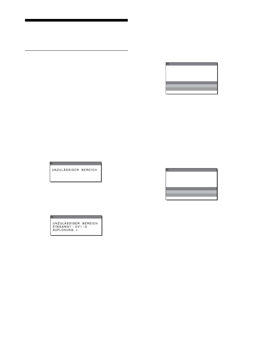
20
Störungsbehebung
Lesen Sie bitte im folgenden Abschnitt nach, bevor Sie sich an
den Kundendienst wenden.
Bildschirmmeldungen
Wenn am Eingangssignal ein Fehler vorliegt, erscheint eine der
folgenden Warnmeldungen auf dem Bildschirm. Schlagen Sie
bitte die zugehörige Abhilfemaßnahme nach (siehe
„Fehlersymptome und Abhilfemaßnahmen“ auf Seite 21).
Wenn „UNZULÄSSIGER BEREICH“ auf dem
Bildschirm erscheint
Diese Meldung gibt an, dass das Eingangssignal nicht den
technischen Daten des Bildschirms entspricht. Überprüfen Sie
Folgendes.
Weitere Informationen zu den Bildschirmmeldungen finden Sie
unter „Fehlersymptome und Abhilfemaßnahmen“ auf Seite 21.
Wenn „xxx.xkHz/ xxxHz“ auf dem Bildschirm
erscheint
Diese Meldung gibt an, dass der Bildschirm die Horizontal-
oder Vertikalfrequenz nicht unterstützt.
Die Zahlen geben die Horizontal- und Vertikalfrequenz des
aktuellen Eingangssignals an.
Wenn „AUFLÖSUNG > 1600
×
1200“ auf dem
Bildschirm erscheint
Diese Meldung gibt an, dass der Bildschirm die Auflösung
nicht unterstützt (1.600 × 1.200 oder weniger).
Wenn „KEIN EING SIGNAL“ auf dem Bildschirm
erscheint
Diese Meldung gibt an, dass am zurzeit ausgewählten Eingang
kein Eingangssignal eingeht.
Wenn EINGANGSERKENN (Seite 17) auf EIN gesetzt ist, sucht
der Bildschirm ein anderes Eingangssignal und wechselt den
Eingang automatisch.
Wenn keine Eingangssignale eingehen, erscheint die
Meldung
„IN STROMSPARMODUS“
.
Nach etwa 5 Sekunden wechselt der Bildschirm in den
Energiesparmodus.
Wenn „KABEL NICHT VERBUNDEN“ auf dem
Bildschirm erscheint
Diese Meldung gibt an, dass das Videosignalkabel nicht mehr an
den zurzeit ausgewählten Eingang angeschlossen ist.
Wenn EINGANGSERKENN (Seite 17) auf EIN gesetzt ist, sucht
der Bildschirm ein anderes Eingangssignal und wechselt den
Eingang automatisch.
Wenn keine Eingangssignale eingehen, erscheint die
Meldung
„IN STROMSPARMODUS“
.
Nach etwa 45 Sekunden wechselt der Bildschirm in den
Energiesparmodus.
x x x . x k H z /
x x x H z
I NFORMA T I ON
E I NGA G1 : DV I - D
N
Beispiel
I NFORMA T I ON
1 6 0 0 X 1 2 0 0
Beispiel
E I NGA G1 : DV I - D
KE I N E I NG S I GNA L
I N S TR
N
OMSPARMODUS
I NFORMA T I ON
Beispiel
KABE L N I CHT VERBUND N
E
I NFORMA T I ON
E I NGA G1 : DV I - D
N
I N S TROMSPARMODUS
Beispiel
21
DE
Fehlersymptome und Abhilfemaßnahmen
Wenn ein Problem auf den angeschlossenen Computer oder andere Geräte zurückzuführen ist, schlagen Sie bitte in der
Bedienungsanleitung zu dem angeschlossenen Computer bzw. Gerät nach.
Symptom
Überprüfen Sie bitte Folgendes
Es wird kein Bild angezeigt
Die Netzanzeige
1
leuchtet nicht auf,
wenn der Netzschalter
1
gedrückt wird.
• Überprüfen Sie, ob das Netzkabel korrekt angeschlossen ist.
• Überprüfen Sie, ob der Bildschirm am Hauptnetzschalter MAIN POWER eingeschaltet ist
(Seite 10).
Die Netzanzeige
1
leuchtet rot.
• Überprüfen Sie, ob der Netzschalter
1
eingeschaltet ist.
„KABEL NICHT VERBUNDEN“
erscheint auf dem Bildschirm.
• Überprüfen Sie, ob das Videosignalkabel korrekt angeschlossen ist und alle Stecker fest in
den Buchsen sitzen (Seite 7).
• Achten Sie darauf, dass am Videoeingangsanschluss keine Stifte verbogen oder eingedrückt sind.
• Überprüfen Sie, ob das richtige Eingangssignal ausgewählt ist (Seite 12).
• Ein nicht mitgeliefertes Videosignalkabel ist angeschlossen. Wenn Sie ein nicht
mitgeliefertes Videosignalkabel anschließen, erscheint unter Umständen KABEL NICHT
VERBUNDEN am Bildschirm. Dabei handelt es sich nicht um eine Fehlfunktion.
Die Meldung „KEIN EING
SIGNAL“ erscheint auf dem
Bildschirm oder die Netzanzeige
1
leuchtet orange.
• Überprüfen Sie, ob das Videosignalkabel korrekt angeschlossen ist und alle Stecker fest in
den Buchsen sitzen (Seite 7).
• Achten Sie darauf, dass am Videoeingangsanschluss keine Stifte verbogen oder eingedrückt sind.
• Überprüfen Sie, ob das richtige Eingangssignal ausgewählt ist (Seite 12).
x
Durch den Computer oder andere angeschlossene Geräte, aber nicht durch
den Bildschirm verursachte Probleme
• Der Computer befindet sich im Stromsparmodus. Drücken Sie eine beliebige Taste auf der
Computertastatur oder bewegen Sie die Maus.
• Überprüfen Sie, ob die Grafikkarte korrekt eingebaut ist.
• Überprüfen Sie, ob der Computer eingeschaltet ist.
• Starten Sie den Computer neu.
„UNZULÄSSIGER BEREICH“
erscheint auf dem Bildschirm
(Seite 20).
x
Durch den Computer oder andere angeschlossene Geräte, aber nicht durch
den Bildschirm verursachte Probleme
• Überprüfen Sie, ob die Videofrequenz im für den Bildschirm angegebenen Bereich liegt. Wenn Sie
einen älteren Bildschirm durch diesen Bildschirm ersetzt haben, schließen Sie den alten Bildschirm
wieder an und stellen Sie dann die Grafikkarte des Computers auf folgende Werte ein:
Horizontal: 28 – 92 kHz (analoges RGB), 28 – 75 kHz (digitales RGB)
Vertikal: 48 – 85 Hz (analoges RGB), 60 Hz (digitales RGB)
Auflösung: 1.600 × 1.200 oder weniger
Sie arbeiten mit Windows.
• Wenn Sie einen älteren Bildschirm durch diesen Bildschirm ersetzt haben, schließen Sie
den alten Bildschirm wieder an und gehen folgendermaßen vor: Wählen Sie in der Liste
„Hersteller“ die Option „SONY“ und wählen Sie dann in der Liste „Modelle“ im
Windows-Geräteauswahlbildschirm das gewünschte Modell. Wenn der Modellname Ihres
Geräts nicht in der Liste „Modelle“ angezeigt wird, versuchen Sie es mit „Plug & Play“.
Sie arbeiten mit einem Macintosh-
System.
• Wenn Sie einen Macintosh anschließen wollen, verwenden Sie gegebenenfalls einen
Adapter (nicht mitgeliefert). Schließen Sie den Adapter an den Computer an, bevor Sie das
Videosignalkabel anschließen.
Das Bild flimmert, springt,
oszilliert oder ist gestört
• Stellen Sie Pitch und Phase ein (nur analoges RGB-Signal) (Seite 16).
• Schließen Sie das Netzkabel des Bildschirms an eine andere Netzsteckdose, möglichst an
einem anderen Stromkreis, an.
x
Durch den Computer oder andere angeschlossene Geräte, aber nicht durch
den Bildschirm verursachte Probleme
• Schlagen Sie in der Anleitung zur Grafikkarte die korrekte Bildschirmeinstellung nach.
• Überprüfen Sie, ob der Grafikmodus (VESA, Macintosh 19 Zoll Farbe usw.) und die Frequenz des
Eingangssignals von diesem Bildschirm unterstützt werden. Auch wenn die Frequenz innerhalb des
unterstützten Bereichs liegt, arbeiten einige Grafikkarten möglicherweise mit einem
Synchronisationsimpuls, der für eine korrekte Synchronisation des Bildschirms zu kurz ist.
• Dieser Bildschirm kann Signale im Zeilensprungmodus nicht verarbeiten. Stellen Sie
progressive Signale ein.
• Stellen Sie die Auffrischungsrate am Computer (Vertikalfrequenz) auf den Wert ein, mit
dem Sie die besten Bilder erzielen.
22
Das Bild ist verschwommen
• Stellen Sie Helligkeit und Kontrast ein (Seite 15).
• Stellen Sie Pitch und Phase ein (nur analoges RGB-Signal) (Seite 16).
x
Durch den Computer oder andere angeschlossene Geräte, aber nicht durch
den Bildschirm verursachte Probleme
• Stellen Sie die Auflösung am Computer auf 1.600
×
1.200 ein.
Doppelbilder sind zu sehen
• Verwenden Sie keine Bildschirmverlängerungskabel und/oder Videoschaltboxen, wenn
dieses Phänomen auftritt.
• Überprüfen Sie, ob alle Stecker fest in den jeweiligen Buchsen sitzen.
Das Bild ist nicht zentriert oder die
Bildgröße ist nicht korrekt
(nur analoges RGB-Signal)
• Stellen Sie Pitch und Phase ein (Seite 16).
• Stellen Sie die Bildposition ein (Seite 16). Beachten Sie, dass bei bestimmten Videomodi
die Anzeige nicht den gesamten Bildschirm füllt.
Das Bild ist zu klein
x
Durch den Computer oder andere angeschlossene Geräte, aber nicht durch
den Bildschirm verursachte Probleme
• Stellen Sie die Auflösung am Computer auf 1.600
×
1.200 ein.
Das Bild ist dunkel
• Stellen Sie die Hintergrundbeleuchtung ein (Seite 15).
• Stellen Sie die Helligkeit ein (Seite 15).
• Stellen Sie über das Menü GAMMA den Gammawert ein (Seite 15).
• Nach dem Einschalten des Bildschirms dauert es einige Minuten, bis der Bildschirm hell
wird.
• Je nach dem ausgewählten ECO-Modus wird der Bildschirm möglicherweise dunkler.
Wellenförmige oder elliptische
Moiré-Effekte sind sichtbar
• Stellen Sie Pitch und Phase ein (nur analoges RGB-Signal) (Seite 16).
Die Farbe ist nicht gleichmäßig
• Stellen Sie Pitch und Phase ein (nur analoges RGB-Signal) (Seite 16).
Weiß sieht nicht weiß aus
• Stellen Sie die Farbtemperatur ein (Seite 15).
Die Bedienelemente am
Bildschirm funktionieren nicht
(
erscheint auf dem
Bildschirm)
• Wenn MENÜ-SPERRE auf „EIN“ gesetzt ist, setzen Sie die Option auf „AUS“ (Seite 17).
Das über das USB-Kabel
angeschlossene Gerät
funktioniert nicht
• Überprüfen Sie, ob das USB-Kabel (mitgeliefert) richtig angeschlossen ist (Seite 8).
• Schalten Sie den Bildschirm am Hauptnetzschalter MAIN POWER und am Netzschalter
1
ein.
x
Durch den Computer oder andere angeschlossene Geräte verursachte
Probleme
• Überprüfen Sie, ob das Gerät eingeschaltet ist.
• Installieren Sie die neueste Version des USB-Treibers. Weitere Informationen dazu
erhalten Sie beim Hersteller des jeweiligen Produkts.
• Wenn sich der Computer mit der an den Bildschirm angeschlossenen Tastatur bzw. Maus
nicht bedienen lässt, schließen Sie die Tastatur bzw. Maus direkt an den Computer an.
Starten Sie den Computer neu und setzen Sie die USB-Verbindung zurück. Schließen Sie
danach die Tastatur bzw. die Maus wieder an den Bildschirm an. Wenn der Bildschirm
über den USB-Anschluss mit einem Computer, einer Tastatur oder einer Maus verbunden
wird, können Sie den Computer damit nach einem Neustart möglicherweise nicht
bedienen.
Der Bildschirm schaltet sich nach
einer Weile aus
x
Durch den angeschlossenen Computer oder andere Geräte verursachte
Probleme
• Deaktivieren Sie die Stromsparfunktion des Computers.
Die auf dem Menübildschirm
angezeigte Auflösung ist nicht
korrekt
• Je nach Grafikkarteneinstellung entspricht die auf dem Menübildschirm angezeigte
Auflösung nicht der Auflösung, die am Computer eingestellt ist.
Wenn die Hauptstromversorgung
ausgeschaltet wird, leuchtet die
Netzanzeige
1
noch eine Weile
• Wenn die Hauptstromversorgung eingeschaltet ist, aber der Netzschalter
1
nicht gedrückt
wurde, oder wenn sich der Monitor im Energiesparmodus befindet, schaltet sich die
Netzanzeige
1
möglicherweise nicht sofort aus, wenn Sie das Gerät am Schalter MAIN
POWER ausschalten. Dies ist keine Fehlfunktion.
Symptom
Überprüfen Sie bitte Folgendes
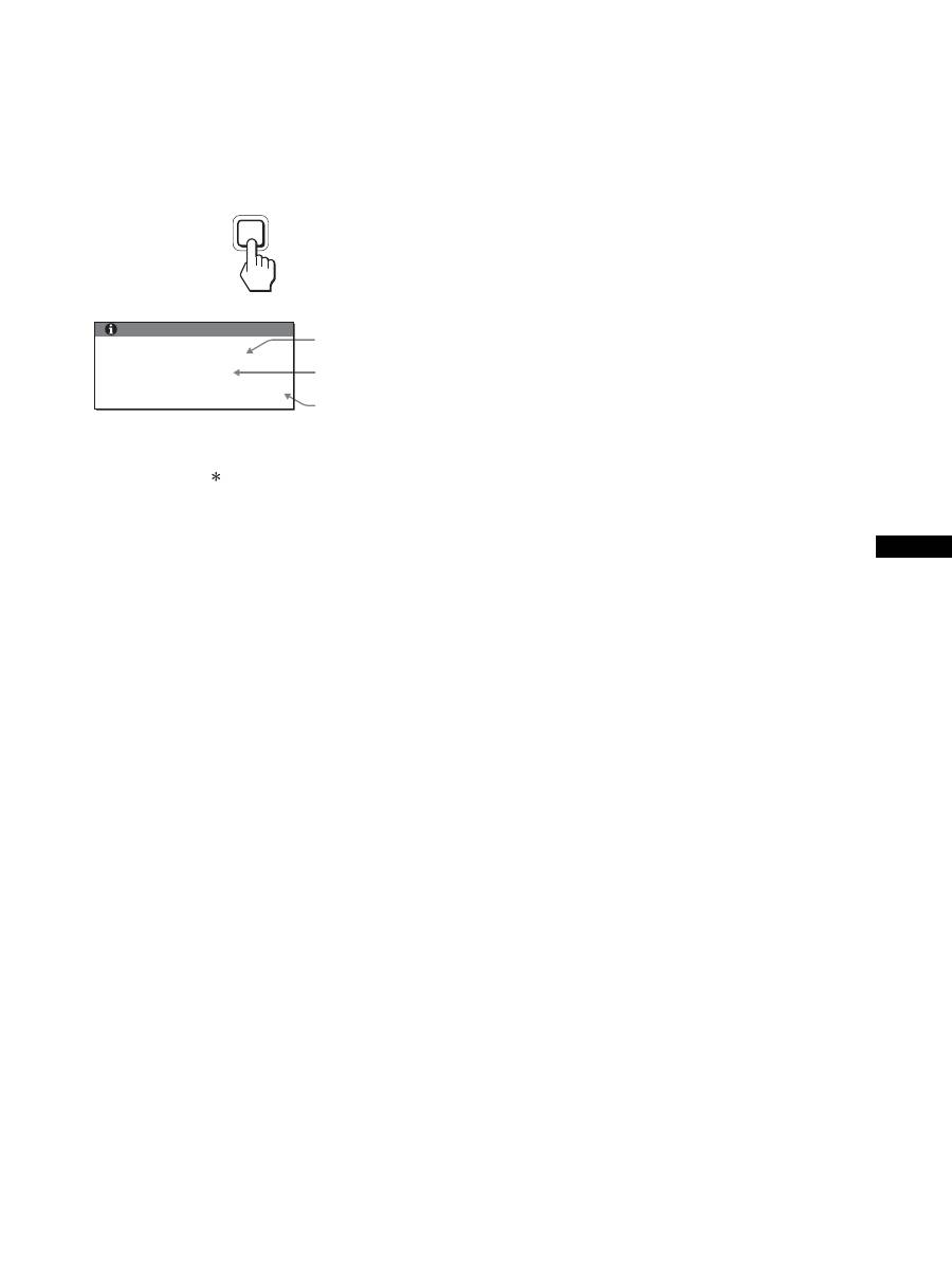
23
DE
Anzeigen von Informationen zu diesem
Bildschirm
Während Videosignale am Bildschirm eingehen, halten
Sie die Taste MENU mehr als 5 Sekunden lang
gedrückt, bis ein Feld mit Informationen erscheint.
Drücken Sie erneut die Taste MENU, um das Feld auszublenden.
Der für den Sicherheitsstandard registrierte Modellname dieses
Geräts lautet SDM-S205 . Im Vertrieb werden jedoch die
Namen SDM-S205F/S205K verwendet.
Lässt sich ein Problem mit den oben angegebenen Maßnahmen
nicht beheben, wenden Sie sich an einen autorisierten Sony-
Händler. Halten Sie die folgenden Informationen bereit:
• Modellname
• Seriennummer
• Detaillierte Beschreibung des Problems
• Kaufdatum
• Modellbezeichnung und technische Daten des Computers und
der Grafikkarte
• Typ der eingespeisten Signale (analoge RGB-Signale/digitale
RGB-Signale)
MENU
INFORMATION
MODEL : SDM-S205F
SER. NO : 1234567
MANUFACTURED : 2005-52
Beispiel
Modellname
Seriennummer
Woche und Jahr
der Herstellung
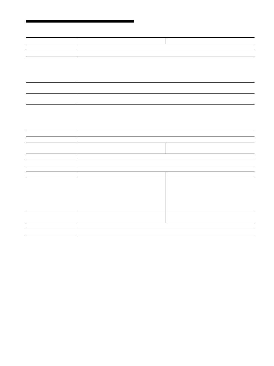
24
Technische Daten
1) Empfohlene Werte für das horizontale und vertikale Timing
• Das horizontale Synchronbreitenverhältnis sollte bei mehr
als 4,8 % des horizontalen Gesamt-Timing oder bei 0,8 µSek.
liegen, je nachdem, welcher Wert höher ist.
• Die horizontale Austastbreite sollte über 2,5 µSek. liegen.
• Die vertikale Austastbreite sollte über 450 µSek. liegen.
Änderungen, die dem technischen Fortschritt dienen, bleiben
vorbehalten.
Modellname
SDM-S205F
SDM-S205K
LCD-Bildschirm
Bildschirmtyp: a-Si-TFT-Aktivmatrix
Bildgröße: Zoll
20,1
Eingangssignalformat
RGB-Betriebsfrequenz
1)
Horizontal: 28 – 92 kHz (Analoges RGB)
28 – 75 kHz (Digitales RGB)
Vertikal: 48 – 85 Hz (Analoges RGB)
60 Hz (Digitales RGB)
Auflösung
Horizontal: bis zu 1.600 Punkte
Vertikal: bis zu 1.200 Zeilen
Art des Eingangssignals
(digital/analog)
1
×
digital/1
×
analog
Eingangssignalpegel Analoges
RGB-Videosignal
0,7 Vp-p, 75
Ω
, positiv
SYNC-Signal
TTL-Pegel, 2,2 k
Ω
, positiv oder negativ
Digitales RGB-Signal (DVI): TMDS (einfache Verbindung)
Audioeingang
Stereo-Minibuchse, 0,5 V effektiver Mittelwert
Audioausgang
Stereo-Minibuchse
USB-Anschluss
–
USB Full-Speed (max. 12 Mbps)
A-Anschluss
×
4, B-Anschluss
×
2
Betriebsspannung
100 – 240 V, 50 – 60 Hz, bis zu 1,2 A
Leistungsaufnahme
bis zu 55 W
Betriebstemperatur
5 – 35 °C
Art des Ständers
Höhenverstellbar
Drehbar
Abmessungen (B/H/T)
ca. 441,5 × 410,5 – 520,5 × 277,5 mm
(mit Ständer)
ca. 441,5 × 356,5 × 74 mm
(ohne Ständer)
ca. 441,5 × 421 – 551 × 277,5 mm
(mit Ständer (normal))
ca. 356,5 × 470,5 – 600,5 × 277,5 mm
(mit Ständer (gedreht))
ca. 441,5 × 356,5 × 74 mm
(ohne Ständer)
Gewicht
ca. 9,6 kg (mit Ständer)
ca. 6,0 kg (ohne Ständer)
ca. 9,9 kg (mit Ständer)
ca. 6,1 kg (ohne Ständer)
Plug & Play
DDC2B
Zubehör
Erläuterungen dazu finden Sie auf Seite 6.

i
TCO’99 Eco-document (for the black
model)
x
Congratulations!
You have just purchased a TCO’99 approved and labelled product! Your
choice has provided you with a product developed for professional use.
Your purchase has also contributed to reducing the burden on the
environment and also to the further development of environmentally
adapted electronics products.
x
Why do we have environmentally labelled com-
puters?
In many countries, environmental labelling has become an established
method for encouraging the adaptation of goods and services to the
environment. The main problem, as far as computers and other electronics
equipment are concerned, is that environmentally harmful substances are
used both in the products and during their manufacture. Since it is not so
far possible to satisfactorily recycle the majority of electronics equipment,
most of these potentially damaging substances sooner or later enter nature.
There are also other characteristics of a computer, such as energy
consumption levels, that are important from the viewpoints of both the
work (internal) and natural (external) environments. Since all methods of
electricity generation have a negative effect on the environment (e.g.
acidic and climate-influencing emissions, radioactive waste), it is vital to
save energy. Electronics equipment in offices is often left running
continuously and thereby consumes a lot of energy.
x
What does labelling involve?
This product meets the requirements for the TCO’99 scheme which
provides for international and environmental labelling of personal
computers. The labelling scheme was developed as a joint effort by the
TCO (The Swedish Confederation of Professional Employees), Svenska
Naturskyddsforeningen (The Swedish Society for Nature Conservation)
and Statens Energimyndighet (The Swedish National Energy
Administration).
Approval requirements cover a wide range of issues: environment,
ergonomics, usability, emission of electric and magnetic fields, energy
consumption and electrical and fire safety.
The environmental demands impose restrictions on the presence and use
of heavy metals, brominated and chlorinated flame retardants, CFCs
(freons) and chlorinated solvents, among other things. The product must
be prepared for recycling and the manufacturer is obliged to have an
environmental policy which must be adhered to in each country where the
company implements its operational policy.
The energy requirements include a demand that the computer and/or
display, after a certain period of inactivity, shall reduce its power
consumption to a lower level in one or more stages. The length of time to
reactivate the computer shall be reasonable for the user.
Labelled products must meet strict environmental demands, for example,
in respect of the reduction of electric and magnetic fields, physical and
visual ergonomics and good usability.
Below you will find a brief summary of the environmental requirements
met by this product. The complete environmental criteria document may
be ordered from:
TCO Development
SE-114 94 Stockholm, Sweden
Fax: +46 8 782 92 07
Email (Internet): development@tco.se
Current information regarding TCO’99 approved and labelled
products may also be obtained via the Internet, using the address:
http://www.tco-info.com/
x
Environmental requirements
Flame retardants
Flame retardants are present in printed circuit boards, cables, wires,
casings and housings. Their purpose is to prevent, or at least to delay the
spread of fire. Up to 30% of the plastic in a computer casing can consist
of flame retardant substances. Most flame retardants contain bromine or
chloride, and those flame retardants are chemically related to another
group of environmental toxins, PCBs. Both the flame retardants
containing bromine or chloride and the PCBs are suspected of giving rise
to severe health effects, including reproductive damage in fish-eating
birds and mammals, due to the bio-accumulative
*
processes. Flame
retardants have been found in human blood and researchers fear that
disturbances in foetus development may occur.
The relevant TCO’99 demand requires that plastic components weighing
more than 25 grams must not contain flame retardants with organically
bound bromine or chlorine. Flame retardants are allowed in the printed
circuit boards since no substitutes are available.
Cadmium
**
Cadmium is present in rechargeable batteries and in the colour-generating
layers of certain computer displays. Cadmium damages the nervous
system and is toxic in high doses. The relevant TCO’99 requirement states
that batteries, the colour-generating layers of display screens and the
electrical or electronics components must not contain any cadmium.
Mercury
**
Mercury is sometimes found in batteries, relays and switches. It damages
the nervous system and is toxic in high doses. The relevant TCO’99
requirement states that batteries may not contain any mercury. It also
demands that mercury is not present in any of the electrical or electronics
components associated with the labelled unit.
CFCs (freons)
The relevant TCO’99 requirement states that neither CFCs nor HCFCs
may be used during the manufacture and assembly of the product. CFCs
(freons) are sometimes used for washing printed circuit boards. CFCs
break down ozone and thereby damage the ozone layer in the stratosphere,
causing increased reception on earth of ultraviolet light with e.g. increased
risks of skin cancer (malignant melanoma) as a consequence.
Lead
**
Lead can be found in picture tubes, display screens, solders and
capacitors. Lead damages the nervous system and in higher doses, causes
lead poisoning. The relevant TCO’99 requirement permits the inclusion of
lead since no replacement has yet been developed.
*
Bio-accumulative is defined as substances which accumulate within
living organisms.
** Lead, Cadmium and Mercury are heavy metals which are Bio-
accumulative.

ii
TCO’03 Eco-document (for the silver
model)
x
Congratulations!
The display you have just purchased carries the TCO’03
Displays label. This means that your display is designed,
manufactured and tested according to some of the strictest
quality and environmental requirements in the world. This
makes for a high performance product, designed with the
user in focus that also minimizes the impact on our natural
environment.
x
Ergonomics
• Good visual ergonomics and image quality in order to
improve the working environment for the user and to
reduce sight and strain problems. Important parameters
are luminance, contrast, resolution, reflectance, colour
rendition and image stability.
x
Energy
• Energy-saving mode after a certain time – beneficial
both for the user and the environment
• Electrical safety
x
Emissions
• Electromagnetic fields
• Noise emissions
x
Ecology
• The product must be prepared for recycling and the
manufacturer must have a certified environmental
management system such as EMAS or ISO 14 001
• Restrictions on
- chlorinated and brominated flame retardants and
polymers
- heavy metals such as cadmium, mercury and lead.
The requirements included in this label have been
developed by TCO Development in co-operation with
scientists, experts, users as well as manufacturers all over
the world. Since the end of the 1980s TCO has been
involved in influencing the development of IT equipment
in a more user-friendly direction. Our labelling system
started with displays in 1992 and is now requested by users
and IT-manufacturers all over the world.
For more information, please visit
www.tcodevelopment.com
Recycling Information
x
Customer in Europe
The collection and recycling of this product has been planned
according to your country’s relevant legislation. To ensure that
this product will be collected and recycled in way that minimizes
the impact on the environment, please do the following:
1. If you purchased this product for private use, contact your
municipality or the waste collection system and bring the
product to this collection point / have the product be picked up
by the waste collection system. Alternatively, your retailer
might take back this if you purchase new equivalent equipment;
please check with your retailer whether he will take back this
product before bringing it. For information on your country’s
recycling arrangements, please contact the Sony representation
in your country (contact details at: www.sony-europe.com).
Further details on specific recycling systems can be found at the
following addresses:
- Belgium: www.recupel.be
- Netherlands: www.nvmp.nl (consumer electronics)
www.ictmilieu.nl (IT equipment)
- Norway: www.elretur.no
- Sweden: www.el-kretsen.se
- Switzerland: www.swico.ch
2. If you use this product professionally, check the product’s
delivery contract for take back / recycling arrangements and
follow the procedures described therein. Alternatively, follow
the procedures described under point 1.
x
Customer in USA
We Sony as a member of EIA recommends to visit URL below
http://www.eiae.org/
x
Customer in Asia
http://www.sony.co.jp/SonyInfo/Environment/recycle/3R.html
Оглавление
- TFT LCD ColorComputer Display
- Monitor de computador en color LCD TFT
- TFT LCD ColorComputer Display
