Sony GDM-F500R: инструкция
Раздел: Компьютерная техника, комплектующие, аксессуары
Тип: Монитор
Инструкция к Монитору Sony GDM-F500R
4-075-035-12 (1)
Trinitron Color
Graphic Display
GB
Operating Instructions
FR
Mode d’emploi
DE
Bedienungsanleitung
ES
Manual de instrucciones
IT
Istruzioni per l’uso
RU
Инструкция по эксплуатации
SE
Bruksanvisning
NL
Gebruiksaanwijzing
GDM-F500R
© 1999 Sony Corporation
Owner’s Record
NOTICE
This notice is applicable for USA/Canada only.
The model and serial numbers are located at the rear of the unit.
If shipped to USA/Canada, install only a UL LISTED/CSA
Record these numbers in the spaces provided below. Refer to them
LABELLED power supply cord meeting the following
whenever you call upon your dealer regarding this product.
specifications:
Model No.
Serial No.
SPECIFICATIONS
Plug Type Nema-Plug 5-15p
Cord Type SVT or SJT, minimum 3
×
18 AWG
WARNING
Length Maximum 15 feet
Rating Minimum 7 A, 125 V
To prevent fire or shock hazard, do not expose the
unit to rain or moisture.
NOTICE
Cette notice s’applique aux Etats-Unis et au Canada
Dangerously high voltages are present inside the
uniquement.
unit. Do not open the cabinet. Refer servicing to
Si cet appareil est export* aux Etats-Unis ou au Canada, utiliser
le cordon d’alimentation portant la mention UL LISTED/CSA
qualified personnel only.
LABELLED et remplissant les conditions suivantes:
FCC Notice
SPECIFICATIONS
This equipment has been tested and found to comply with the limits
Type de fiche Fiche Nema 5-15 broches
for a Class B digital device, pursuant to Part 15 of the FCC Rules.
Cordon Type SVT ou SJT, minimum 3
×
18 AWG
These limits are designed to provide reasonable protection against
Longueur Maximum 15 pieds
harmful interference in a residential installation. This equipment
Tension Minimum 7 A, 125 V
generates, uses, and can radiate radio frequency energy and, if not
installed and used in accordance with the instructions, may cause
harmful interference to radio communications. However, there is no
guarantee that interference will not occur in a particular installation.
If this equipment does cause harmful interference to radio or
television reception, which can be determined by turning the
equipment off and on, the user is encouraged to try to correct the
interference by one or more of the following measures:
As an
E
NERGY
S
TAR Partner, Sony
– Reorient or relocate the receiving antenna.
Corporation has determined that this
– Increase the separation between the equipment and receiver.
product meets the
E
NERGY
S
TAR
– Connect the equipment into an outlet on a circuit different from
guidelines for energy efficiency.
that to which the receiver is connected.
– Consult the dealer or an experienced radio/TV technician for help.
You are cautioned that any changes or modifications not expressly
approved in this manual could void your authority to operate this
equipment.
EN 55022 Compliance (Czech Republic Only)
This monitor complies with the
This device belongs to category B devices as described in EN
TCO’99 guidelines.
55022, unless it is specifically stated that it is a category A
device on the specification label. The following applies to
devices in category A of EN 55022 (radius of protection up to
30 meters). The user of the device is obliged to take all steps
necessary to remove sources of interference to
telecommunication or other devices.
Declaration of Conformity
Trade Name: Sony
Model No.: GDM-F500R
Responsible Party: Sony Electronics Inc.
Address: 1 Sony Drive, Park Ridge, NJ. 07656 USA
Telephone No.: 201-930-6970
INFORMATION
This device complies with Part 15 of the FCC Rules. Operation is
This product complies with Swedish National Council for Metrology
subject to the following two conditions: (1) This device may not
(MPR) standards issued in December 1990 (MPR II) for very low
cause harmful interference, and (2) this device must accept any
frequency (VLF) and extremely low frequency (ELF).
interference received, including interference that may cause
INFORMATION
undesired operation.
Ce produit est conforme aux normes du Swedish National Council
for Metrology de décembre 1990 (MPR II) en ce qui concerne les
fréquences très basses (VLF) et extrêmement basses (ELF).
INFORMACIÓN
Este producto cumple las normas del Consejo Nacional Sueco para
Metrología (MPR) emitidas en diciembre de 1990 (MPR II) para
frecuencias muy bajas (VLF) y frecuencias extremadamente bajas (ELF).
2
Table of Contents
Precautions. . . . . . . . . . . . . . . . . . . . . . . . . . . . . . . . . . . . . . . . . . . . 4
Identifying parts and controls . . . . . . . . . . . . . . . . . . . . . . . . . . . . . . 5
Setup. . . . . . . . . . . . . . . . . . . . . . . . . . . . . . . . . . . . . . . . . .6
Step 1:
Connect your monitor to your computer . . . . . . . . . . . . . . . 6
Step 2:
Connect the power cord. . . . . . . . . . . . . . . . . . . . . . . . . . . . 7
Step 3:
Turn on the monitor and computer . . . . . . . . . . . . . . . . . . . 7
Connecting Universal Serial Bus (USB) compliant peripherals . . . . 8
Selecting the on-screen menu language (LANG). . . . . . . . . . . . . . . 8
Selecting the input signal . . . . . . . . . . . . . . . . . . . . . . . . . . . . . . . . . 9
Automatically sizing and centering the picture (AUTO) . . . . . . . . . . 9
Customizing Your Monitor . . . . . . . . . . . . . . . . . . . . . . .10
Navigating the menu. . . . . . . . . . . . . . . . . . . . . . . . . . . . . . . . . . . . 10
Adjusting the brightness and contrast. . . . . . . . . . . . . . . . . . . . . . . 11
Adjusting the size of the picture (SIZE) . . . . . . . . . . . . . . . . . . . . . 11
Adjusting the centering of the picture (CENTER) . . . . . . . . . . . . . . 12
GB
Enlarging or reducing the picture (ZOOM) . . . . . . . . . . . . . . . . . . . 12
Adjusting the shape of the picture (GEOM) . . . . . . . . . . . . . . . . . . 12
Adjusting the convergence (CONV) . . . . . . . . . . . . . . . . . . . . . . . . 12
Adjusting the quality of the picture (SCREEN) . . . . . . . . . . . . . . . . 13
Adjusting the color of the picture (COLOR) . . . . . . . . . . . . . . . . . . 13
Additional settings (OPTION) . . . . . . . . . . . . . . . . . . . . . . . . . . . . . 15
Resetting the adjustments . . . . . . . . . . . . . . . . . . . . . . . . . . . . . . . 16
Technical Features . . . . . . . . . . . . . . . . . . . . . . . . . . . . .16
• Trinitron
is a registered trademark of
Sony Corporation.
Preset and user modes. . . . . . . . . . . . . . . . . . . . . . . . . . . . . . . . . . 16
• Macintosh is a trademark licensed to
Apple Computer, Inc., registered in the
Power saving function. . . . . . . . . . . . . . . . . . . . . . . . . . . . . . . . . . . 16
U.S.A. and other countries.
• Windows
and MS-DOS are registered
trademarks of Microsoft Corporation in
Troubleshooting. . . . . . . . . . . . . . . . . . . . . . . . . . . . . . . .17
the United States and other countries.
• IBM PC/AT and VGA are registered
If thin lines appear on your screen (damper wires). . . . . . . . . . . . . 17
trademarks of IBM Corporation of the
On-screen messages . . . . . . . . . . . . . . . . . . . . . . . . . . . . . . . . . . . 17
U.S.A.
• VESA and DDC
are trademarks of the
Trouble symptoms and remedies . . . . . . . . . . . . . . . . . . . . . . . . . . 18
Video Electronics Standard
Self-diagnosis function . . . . . . . . . . . . . . . . . . . . . . . . . . . . . . . . . . 20
Association.
•
E
NERGY
S
TAR is a U.S. registered
mark.
Specifications. . . . . . . . . . . . . . . . . . . . . . . . . . . . . . . . . .20
• All other product names mentioned
herein may be the trademarks or
registered trademarks of their respective
Appendix. . . . . . . . . . . . . . . . . . . . . . . . . . . . . . . . . . . . . . . i
companies.
• Furthermore, “
” and “
” are not
Preset mode timing table . . . . . . . . . . . . . . . . . . . . . . . . . . . . . . . . . .i
mentioned in each case in this manual.
TCO’99 Eco-document . . . . . . . . . . . . . . . . . . . . . . . . . . . . . . . . . . . .i
3
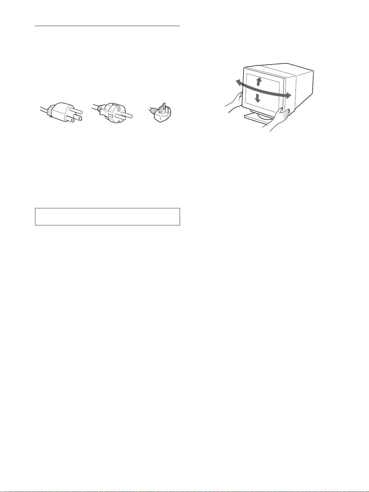
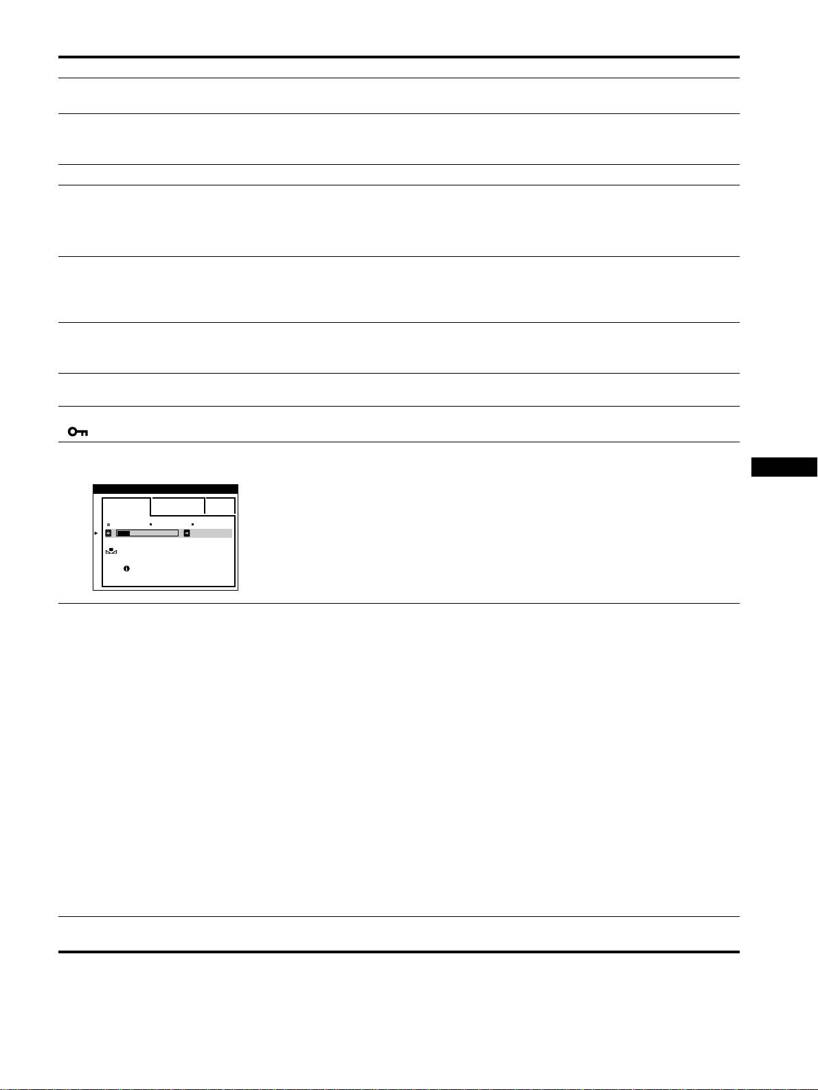
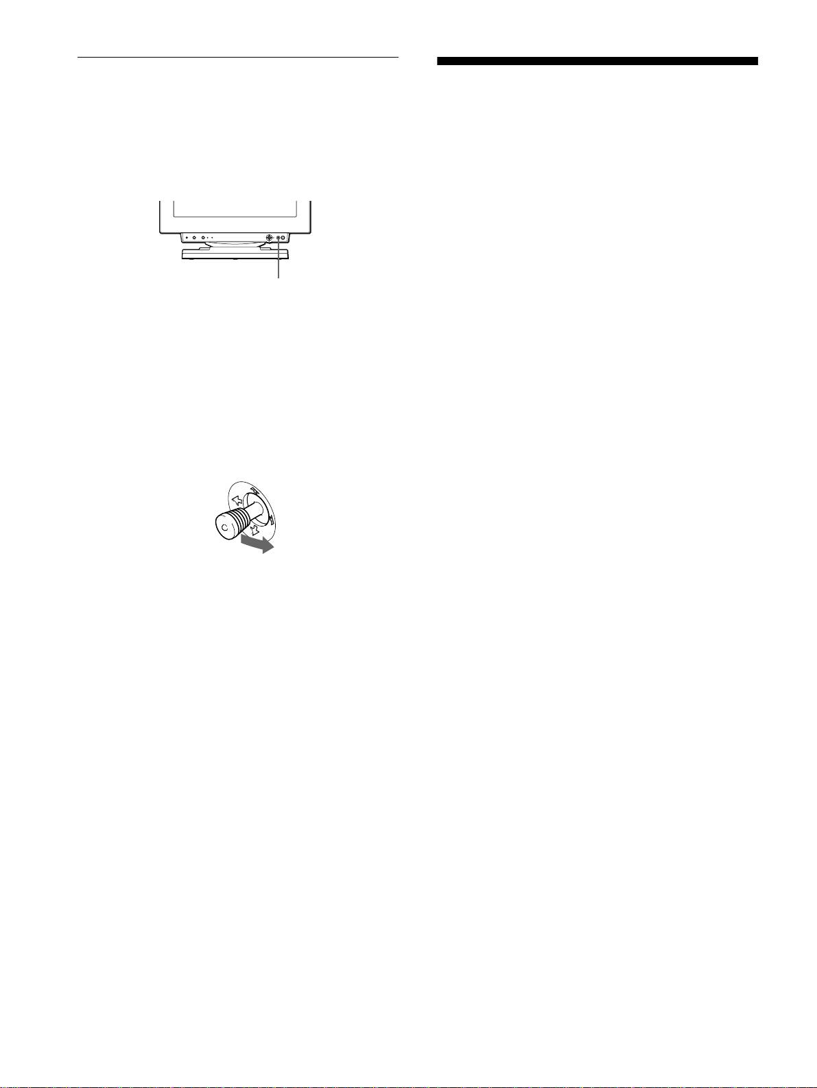
Use of the tilt-swivel
Precautions
This monitor can be adjusted within the angles shown below. To
turn the monitor vertically or horizontally, hold it at the bottom
Warning on power connections
with both hands.
• Use the supplied power cord. If you use a different power cord,
be sure that it is compatible with your local power supply.
For the customers in the UK
If you use the monitor in the UK, be sure to use the supplied UK
power cable.
Example of plug types
for 100 to 120 V AC for 200 to 240 V AC for 240 V AC only
• Before disconnecting the power cord, wait at least 30 seconds
after turning off the power to allow the static electricity on the
screen’s surface to discharge.
• After the power is turned on, the screen is demagnetized
(degaussed) for about 3 seconds. This generates a strong
magnetic field around the screen which may affect data stored
on magnetic tapes and disks placed near the monitor. Be sure to
keep magnetic recording equipment, tapes, and disks away
from the monitor.
The equipment should be installed near an easily accessible
outlet.
Installation
Do not install the monitor in the following places:
• on surfaces (rugs, blankets, etc.) or near materials (curtains,
draperies, etc.) that may block the ventilation holes
• near heat sources such as radiators or air ducts, or in a place
subject to direct sunlight
• in a place subject to severe temperature changes
• in a place subject to mechanical vibration or shock
• on an unstable surface
• near equipment which generates magnetism, such as a
transformer or high voltage power lines
• near or on an electrically charged metal surface
Maintenance
• Clean the screen with a soft cloth. If you use a glass cleaning
liquid, do not use any type of cleaner containing an anti-static
solution or similar additive as this may scratch the screen’s
coating.
• Do not rub, touch, or tap the surface of the screen with sharp or
abrasive items such as a ballpoint pen or screwdriver. This type
of contact may result in a scratched picture tube.
• Clean the cabinet, panel and controls with a soft cloth lightly
moistened with a mild detergent solution. Do not use any type
of abrasive pad, scouring powder or solvent, such as alcohol or
benzene.
Transportation
When you transport this monitor for repair or shipment, use the
original carton and packing materials.
4
90°
15°
90°
5°

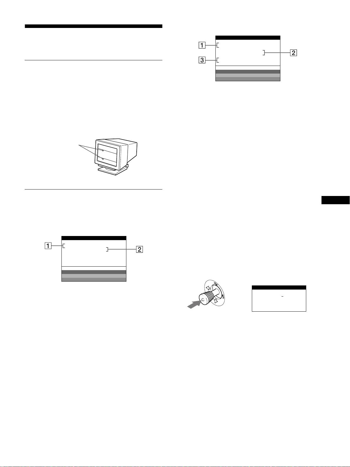
Identifying parts and controls
See the pages in parentheses for further details.
Front
Rear
forward side
forward side
rear side
rear side
AC IN
RGBHDVD
1
2
(HD15)
(BNC)
RESET ASC INPUT MENUHD15 BNC
1 RESET (reset) button (page 16)
9 Video input 1 connector (HD15) (page 6)
This button resets the adjustments to the factory settings.
This connector inputs RGB video signals (0.700 Vp-p,
positive) and sync signals.
GB
2 ASC (auto sizing and centering) button (page 9)
This button automatically adjusts the size and centering of the
picture.
3 INPUT button and HD15 / BNC indicators (page 9)
This button selects the HD15 or BNC video input signal.
Each time you press this button, the input signal and
Pin No. Signal
corresponding indicator alternate.
1Red
4 Joystick (page 11)
2 Green
The joystick is used to display the menu and make
(Composite Sync on Green)
adjustments to the monitor, including brightness and contrast
3Blue
adjustments.
4 ID (Ground)
5 1 (power) switch and indicator (pages 7, 16, 20)
5 DDC Ground*
This button turns the monitor on and off. The power indicator
6 Red Ground
lights up in green when the monitor is turned on, and either
flashes in green and orange, or lights up in orange when the
7 Green Ground
monitor is in power saving mode.
8 Blue Ground
9 DDC + 5V*
6 AC IN connector (page 7)
This connector provides AC power to the monitor.
10 Ground
11 ID (Ground)
7 USB (universal serial bus) upstream connector
12 Bi-Directional Data (SDA)*
(page 8)
Use this connector to link the monitor to a USB compliant
13 H. Sync
computer.
14 V. Sync
8 USB (universal serial bus) downstream connectors
15 Data Clock (SCL)*
(page 8)
* DDC (Display Data Channel) is a standard of VESA.
Use these connectors to link USB peripheral devices to the
monitor.
q; Video input 2 connector (BNC) (page 6)
This connector inputs RGB video signals (0.700 Vp-p,
positive) and sync signals.
5
5 4 3 2
1
678910
1112131415
x
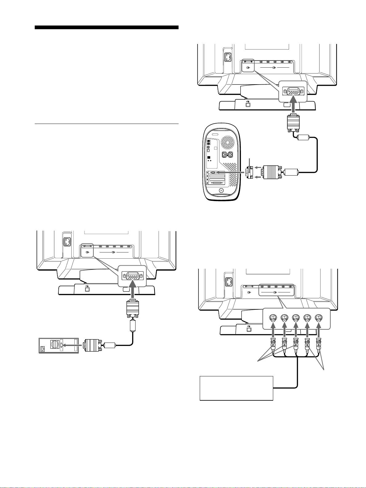
Connecting to a Macintosh computer
Setup
Before using your monitor, check that the following accessories
are included in your carton:
• Power cord (1)
• HD15 video signal cable (1)
• USB cable (1)
• G3 adapter (for Macintosh blue and white system) (1)
• Setup Disk (1)
• Warranty card (1)
• Notes on cleaning the screen’s surface (1)
• This instruction manual (1)
Step 1:Connect your monitor to
your computer
Turn off the monitor and computer before connecting.
Notes
• Do not touch the pins of the video signal cable connector as this might
bend the pins.
• When connecting the video signal cable, check the alignment of the
HD15 connector. Do not force the connector in the wrong way or the
pins might bend.
x
Connecting to an IBM PC/AT or compatible
* Connect the supplied Macintosh adapter to the computer before
computer
connecting the cable. This adapter is compatible with the Power
Macintosh G3 computer that has three rows of pins. If you are
AC IN
connecting to the other version of Power Macintosh G3 series computer
with two rows of pins or other models, you will need a different adapter
(sold separately).
RGBHDVD
1
2
(HD15)
(BNC)
x
Connecting to the five BNC connectors
to HD15
to video output
HD15 video signal
IBM PC/AT or compatible
cable (supplied)
computer
* Connect the cables from left to right in the following order: Red-Green-
Blue-HD-VD.
Note
Plug & Play (DDC) does not apply to the five BNC connectors. If you
want to use Plug & Play, connect your computer to the HD15 connector
using the supplied video signal cable.
6
AC IN
RGBHDVD
1
2
(HD15)
(BNC)
Use the supplied G3 adapter (for blue and white system).
to HD15
G3 adapter (for blue
and white system)
(supplied)
*
HD15 video signal
to video
cable (supplied)
output
Power Macintosh G3
AC IN
RGBHDVD
1
2
(HD15)
(BNC)
to VIDEO IN R/G/B
to SYNC IN
HD/VD
Refer to the preceding
examples to connect to your
computer. video signal cable
(SMF-400, not supplied)
*
If no picture appears on your screen
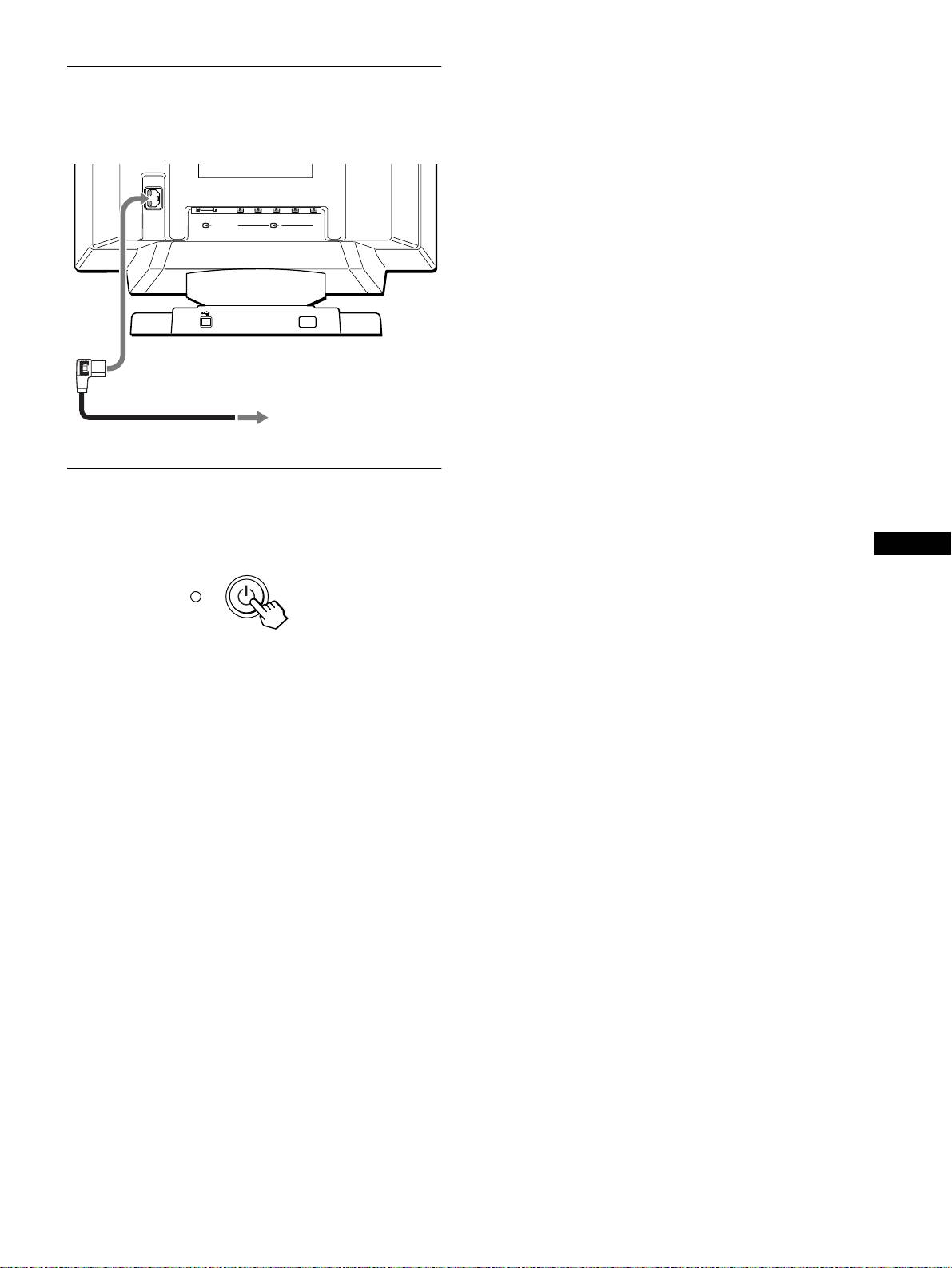
Step 2:Connect the power cord
• Check that the monitor is correctly connected to the computer.
• If NO INPUT SIGNAL appears on the screen, try changing the
With the monitor and computer switched off, first connect the
input signal (page 9), and confirm that your computer’s graphic
power cord to the monitor, then connect it to a power outlet.
board is completely seated in the correct bus slot.
• If you are replacing an old monitor with this model and OUT
AC IN
OF SCAN RANGE appears on the screen, reconnect the old
monitor. Then adjust the computer’s graphic board so that the
RGBHDVD
horizontal frequency is between 30 – 121 kHz, and the vertical
1
2
(HD15)
(BNC)
frequency is between 48 – 160 Hz.
For more information about the on-screen messages, see “Trouble
symptoms and remedies” on page 18.
to AC IN
Setup on various OS (Operating System)
This monitor complies with the “DDC” Plug & Play standard and
automatically detects all the monitor’s information with the Windows
Plug & Play function. No specific driver needs to be installed to the
computer.
to a power outlet
If you connect the monitor to your PC, and then boot your PC for the first
power cord (supplied)
time, the setup Wizard may be displayed on the screen. Click on “Next”
several times according to the instructions from the Wizard until the Plug
& Play Monitor is automatically selected so that you can use this monitor.
If your PC/graphics board has difficulty communicating with this
Step 3:Turn on the monitor and
monitor, load the supplied Setup Disk. Refer to the “Read Me” file on the
computer
Disk about the procedure to install. You can also download the
information by accessing the web site of the graphics board’s
First turn on the monitor, then turn on the computer.
manufacturer.
GB
For customers using Windows NT4.0
Monitor setup in Windows NT4.0 does not use the display driver. Refer
to the Windows NT4.0 instruction manual for further details on adjusting
the resolution, refresh rate, and number of colors.
The installation of your monitor is complete.
If necessary, use the monitor’s controls to adjust the picture.
7
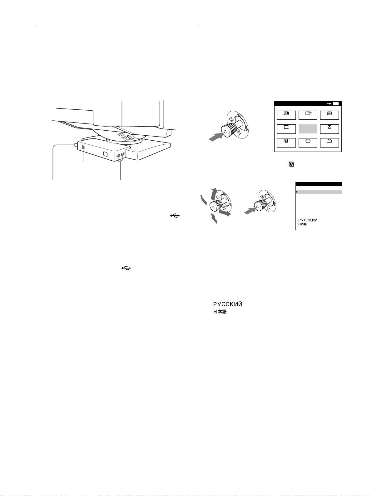
Connecting Universal Serial Bus
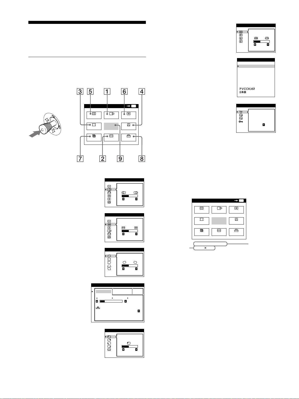
Selecting the on-screen menu
(USB) compliant peripherals
language (LANG)
Your monitor has one upstream and four downstream USB
English, French, German, Spanish, Italian, Dutch, Swedish,
connectors. They provide a fast and easy way to connect USB
Russian and Japanese versions of the on-screen menus are
compliant peripheral devices (such as keyboards, mice, printers
available. The default setting is English.
and scanners) to your computer using a standardized USB cable.
To use your monitor as a hub for your peripheral devices, connect
1
Press the joystick.
the USBs as illustrated below.
See page 11 for more information on using the joystick.
MENU
OK
MENU
SCREEN
CENTER
CONV
GEOM
EXIT
COLOR
LANG
SIZE
OPTION
2
Move the joystick to highlight LANG and press
to a USB compliant
computer
the joystick again.
to USB compliant
to USB compliant
peripheral devices
peripheral devices
1
Turn on the monitor and computer.
2
Connect your computer to the square upstream
connector using the supplied USB cable.
For customers using Windows
If a message appears on your screen, follow the on-screen instructions
3
Move the joystick up or down to select a language
and select Generic USB Hub as the default setting.
and press the joystick again.
• ENGLISH
3
Connect your USB compliant peripheral devices to
• FRANÇAIS: French
the rectangular downstream USB connectors.
• DEUTSCH: German
• ESPAÑOL: Spanish
Notes
• ITALIANO: Italian
• Not all computers and /or operating systems support USB
• NEDERLANDS: Dutch
configurations. Check your computer’s instruction manual to see if you
• SVENSKA: Swedish
can connect USB devices.
• In most cases, USB driver software needs to be installed on the host
• : Russian
computer. Refer to the peripheral device’s instruction manual for
• : Japanese
further details.
• The monitor functions as a USB hub as long as the monitor is either
To close the menu
“on” or in power saving mode.
Press the joystick once to return to the main menu, and twice to return to
• If you connect a keyboard or mouse to the USB connectors and then
normal viewing. If no buttons are pressed, the menu closes automatically
boot your computer for the first time, the peripheral devices may not
after about 30 seconds.
function. First connect the keyboard and mouse directly to the
computer and set up the USB compliant devices. Then connect them to
To reset to English
this monitor.
Press the RESET button while the LANGUAGE menu is displayed on the
• Do not lean on the monitor when plugging in the USB cables. The
screen.
monitor may suddenly shift and cause injury.
8
b
LANGUAGE
ENGL I SH
FRANÇA IS
DEUTSCH
ESPAÑOL
ITALIANO
NEDERLANDS
SVENSKA
bb
x
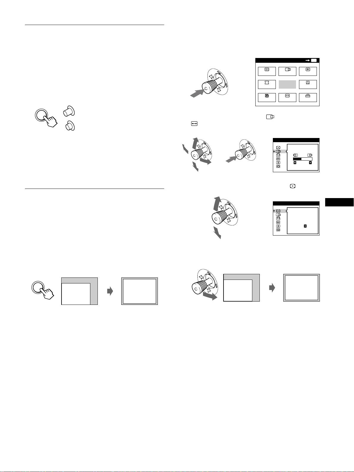
Using the on-screen menu
Selecting the input signal
1
Press the joystick to display the main MENU on the
You can connect two computers to this monitor using the HD15
screen.
and BNC connectors. To switch between the two computers, use
the
INPUT
button.
MENU
OK
MENU
Press the INPUT button.
SCREEN
CENTER
CONV
Each time you press this button, the input signal and
corresponding indicator alternate.
b
GEOM
EXIT
COLOR
When the button is pressed, BNC is selected, when the button is
unpressed, HD15 is selected.
LANG
SIZE
OPTION
HD15
2
Move the joystick to highlight CENTER or
SIZE and press the joystick again.
INPUT
BNC
The selected connector appears on the screen for a few seconds.
SIZE/CENTER
“HD15” or “BNC” appears on the screen.
bb
Note
26
If no signal is input to the selected connector, NO INPUT SIGNAL
appears on the screen. After a few seconds, the monitor enters the power
saving mode. If this happens, switch to the other connector.
3
Move the joystick up or down to select (AUTO).
Automatically sizing and centering
SIZE/CENTER
GB
the picture (AUTO)
AUTO
You can easily adjust the picture to fill the screen by pressing the
b
ASC (auto sizing and centering) button, or by using the on-screen
ON
menu.
x
Using ASC button
4
Move the joystick to the right ,.
The picture automatically fills the screen.
Press the ASC button.
The picture automatically fills the screen.
ASC
Notes
• This function is intended for use with a computer running Windows or
similar graphic user interface software that provides a full-screen
picture. It may not work properly if the background color is dark or if
the input picture does not fill the screen to the edges (such as an MS-
DOS prompt).
• Pictures with an aspect ratio of 5:4 (resolution: 1280 × 1024, 1800 ×
1440) are displayed at their actual resolution and do not fill the screen
to the edges.
• The displayed image moves for a few seconds while this function is
performed. This is not a malfunction.
9
6 CONV (page 12)
CONVERGENCE
Customizing Your Monitor
Select the CONV menu to adjust the
picture’s horizontal and vertical
TOP
You can make numerous adjustments to your monitor using the
convergence.
BOT
26
on-screen menu.
7 LANG (page 8)
LANGUAGE
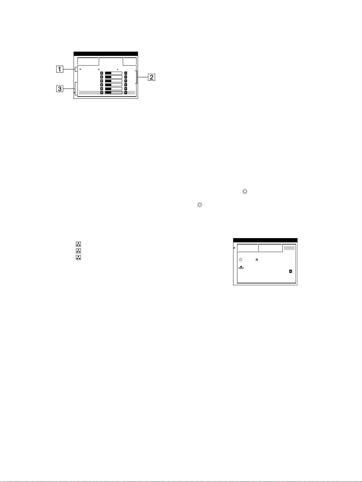
Navigating the menu
Select the LANG menu to choose
ENGL ISH
FRANÇA IS
the on-screen menu’s language.
Press the joystick to display the main MENU on your screen. See
DEUTSCH
ESPAÑOL
page 11 for more information on using the joystick.
ITALIANO
NEDERLANDS
SVENSKA
MENU
OK
MENU
8 OPTION (page 15)
OPT ION
Select the OPTION menu to adjust
DEGAUSS
SCREEN
CENTER
CONV
the monitor’s options. The options
include:
ON
b
GEOM
EXIT
COLOR
• degaussing the screen
• changing the on-screen menu
LANG
SIZE
OPTION
position
• locking the controls
9 EXIT
Select EXIT to close the menu.
Use the joystick to select one of the following menus.
x
Displaying the current input signal
1 CENTER (page 12)
SIZE/CENTER
The horizontal and vertical frequencies of the current input signal
Select the CENTER menu
are displayed in the main MENU. If the signal matches one of this
to adjust the picture’s
monitor’s factory preset modes, the resolution is also displayed.
centering, size or zoom.
26
2 SIZE (page 11)
SIZE/CENTER
Select the SIZE menu to
adjust the picture’s size,
centering or zoom.
26
3 GEOM (page 12)
GEOMETRY
Select the GEOM menu to adjust the
picture’s rotation and shape.
26
4 COLOR (page 13)
COLOR
Select the COLOR menu to
EASY EXPERT s BGR
adjust the picture’s color
5000K 6500K 930 K0
temperature. You can use
50 K00
this to match the monitor’s
IMAGE
colors to a printed picture’s
RESTORATION ON
colors.
5 SCREEN (page 13)
SCREEN
Select the SCREEN menu to adjust
LANDING
the picture’s quality. You can adjust
the landing and moire cancellation
26
effect.
10
MENU
OK
MENU
SCREEN
CENTER
CONV
GEOM
EXIT
COLOR
LANG
SIZE
OPTION
68.7kHz/ 85Hz
1024
768
the horizontal
the resolution
and vertical
of the current
frequencies of
input signal
the current
input signal
x
Using the joystick
Adjusting the brightness and
1
Display the main MENU and select the menu you
contrast
want to adjust.
Press the joystick once to display the main MENU. Then
Brightness and contrast adjustments are made using a separate
move the joystick up, down, left, or right to highlight the
BRIGHTNESS/CONTRAST menu.
desired menu. Press the joystick to select the menu item.
These settings are stored in memory for the signals from the
currently selected input connector.
1
Move the joystick in any direction.
The BRIGHTNESS/CONTRAST menu appears on the
bb
screen.
2
Adjust the menu.
Move the joystick up, down, left, or right to make the
adjustment.
2
Move the joystick up or down to adjust the
brightness ( ), and left or right to adjust the
contrast (6).
If you are using the sRGB mode
If you selected the sRGB mode in the COLOR menu, the
following BRIGHTNESS/CONTRAST menu appears on the
screen.
GB
3
Close the menu.
Press the joystick once to return to the main menu, and twice
to return to normal viewing. If no buttons are pressed, the
menu closes automatically after about 30 seconds.
For more information about using the sRGB mode, see
“Adjusting the color of the picture (COLOR)” on page 13.
The menu automatically disappears after about 3 seconds.
x
Resetting the adjustments
Adjusting the size of the picture
Press the RESET button. See page 16 for more information on
(SIZE)
resetting the adjustments.
This setting is stored in memory for the current input signal.
1
Press the joystick.
RESET
The main MENU appears on the screen.
2
Move the joystick to highlight SIZE and press the
joystick again.
The SIZE/CENTER menu appears on the screen.
3
First move the joystick up or down to select for
horizontal adjustment, or for vertical
adjustment. Then move the joystick left or right to
adjust the size.
11
BRIGHTNESS/CONTRAST
26 26
BRIGHTNESS/CONTRAST
56 76
sRGB : 56 76
3
First move the joystick up or down to select the
Adjusting the centering of the
desired adjustment item. Then move the joystick left
or right to make the adjustment.
picture (CENTER)
This setting is stored in memory for the current input signal.
Select To
rotate the picture
1
Press the joystick.
The main MENU appears on the screen.
expand or contract the picture sides
shift the picture sides to the left or right
2
Move the joystick to highlight CENTER and
press the joystick again.
adjust the picture width at the top of the screen
The SIZE/CENTER menu appears on the screen.
shift the picture to the left or right at the top of the
screen
3
First move the joystick up or down to select for
horizontal adjustment, or for vertical adjustment.
Then move the joystick left or right to adjust the
centering.
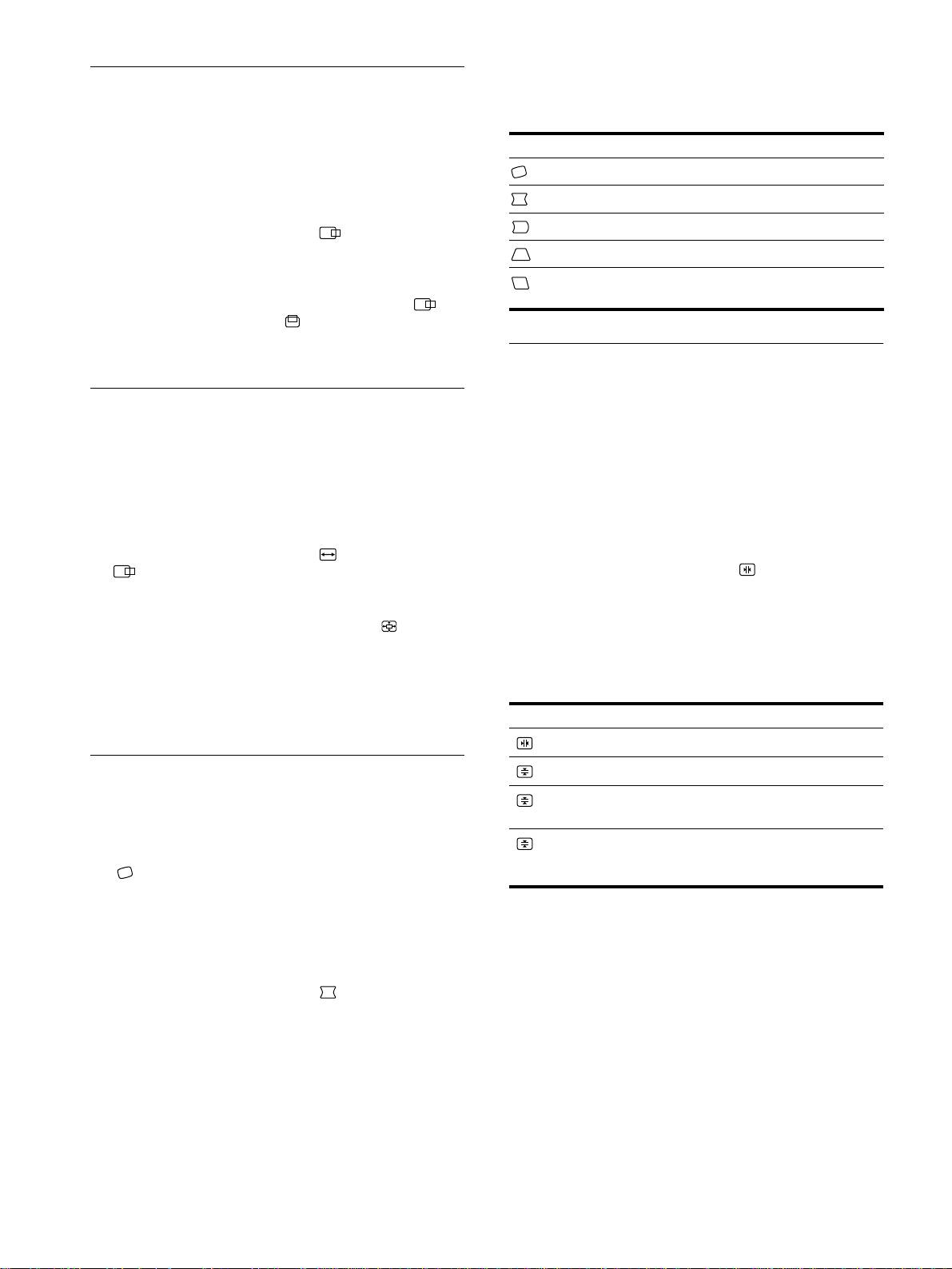
Adjusting the convergence (CONV)
The CONV settings allow you to adjust the quality of the picture
Enlarging or reducing the picture
by controlling the convergence. The convergence refers to the
(ZOOM)
alignment of the red, green, and blue color signals.
If you see red or blue shadows around letters or lines, adjust the
This setting is stored in memory for the current input signal.
convergence.
These settings are stored in memory for all input signals.
1
Press the joystick.
The main MENU appears on the screen.
1
Press the joystick.
The main MENU appears on the screen.
2
Move the joystick to highlight SIZE or
CENTER and press the joystick again.
2
Move the joystick to highlight CONV and press
The SIZE/CENTER menu appears on the screen.
the joystick again.
The CONVERGENCE menu appears on the screen.
3
Move the joystick up or down to select (zoom),
and move the joystick left or right to enlarge or
3
First move the joystick up or down to select the
reduce the picture.
desired adjustment item. Then move the joystick left
or right to make the adjustment.
Note
Adjustment stops when either the horizontal or vertical size reaches its
Select To
maximum or minimum value.
horizontally shift red or blue shadows
vertically shift red or blue shadows
Adjusting the shape of the picture
vertically shift red or blue shadows at
(GEOM)
TOP
V CONVER TOP
the top of the screen
The GEOM settings allow you to adjust the rotation and shape of
vertically shift red or blue shadows at
BOT
the picture.
V CONVER
the bottom of the screen
The (rotation) setting is stored in memory for all input signals.
BOTTOM
All other settings are stored in memory for the current input
signal.
1
Press the joystick.
The main MENU appears on the screen.
2
Move the joystick to highlight GEOM and press
the joystick again.
The GEOMETRY menu appears on the screen.
12
Adjusting the quality of the picture
Adjusting the color of the picture
(SCREEN)
(COLOR)
The SCREEN settings allow you to adjust the quality of the
The COLOR settings allow you to adjust the picture’s color
picture by controlling the moire and landing.
temperature by changing the color level of the white color field.
• If the color is irregular at the corners of the screen, adjust the
Colors appear reddish if the temperature is low, and bluish if the
landing.
temperature is high. This adjustment is useful for matching the
• If elliptical or wavy patterns appear on the screen, cancel the
monitor’s color to a printed picture’s colors.
moire.
The CANCEL MOIRE and MOIRE ADJUST settings are stored
1
Press the joystick.
in memory for the current input signal. All other settings are
The main MENU appears on the screen.
stored in memory for all input signals.
2
Move the joystick to highlight COLOR and press
1
Press the joystick.
the joystick again.
The main MENU appears on the screen.
The COLOR menu appears on the screen.
2
Move the joystick to highlight SCREEN and
3
Move the joystick left or right to select the
press the joystick again.
adjustment mode.
The SCREEN menu appears on the screen.
There are three types of adjustment modes, EASY, EXPERT
and sRGB.
3
First move the joystick up or down to select the
desired adjustment item. Then move the joystick left
4
First move the joystick up or down to select the
or right to make the adjustment.
desired adjustment item. Then move the joystick left
or right to make the adjustment.
Select To
Adjust the selected mode according to the following
instructions.
reduce any color irregularities in the
GB
LANDING
screen’s top left corner to a minimum.
EASY mode
reduce any color irregularities in the
COLOR
LANDING
screen’s top right corner to a
EASY EXPERT s BGR
minimum.
5000K 6500K 930 K0
reduce any color irregularities in the
50 K00
LANDING
screen’s bottom left corner to a
IMAGE
minimum.
RESTORATION ON
reduce any color irregularities in the
LANDING
screen’s bottom right corner to a
minimum.
1
Move the joystick up or down to select the color
turn the moire cancellation function
temperature row 1. Then move the joystick left or
CANCEL MOIRE
*
ON or OFF.
right to select a color temperature.
(MOIRE ADJUST) appears in
The preset color temperatures are 5000K, 6500K, and 9300K.
the menu when you select ON.
Since the default setting is 9300K, the whites will change
from a bluish hue to a reddish hue as the temperature is
adjust the degree of moire
lowered to 6500K and 5000K.
MOIRE ADJUST
cancellation until the moire is at a
minimum.
2
If necessary, fine tune the color temperature.
* Moire is a type of natural interference which produces soft, wavy lines
Move the joystick up or down to select the color
on your screen. It may appear due to interference between the pattern
temperature row 2. Then move the joystick left or
of the picture on the screen and the phosphor pitch pattern of the
right to fine tune the color temperature.
monitor.
If you fine tune the color temperature, the new color settings
are stored in memory for each of the three color temperatures
Example of moire
and item 1 of the on-screen menu changes as follows.
• [5000K]t[1]
• [6500K]t[2]
• [9300K]t[3]
Note
The picture may become fuzzy when CANCEL MOIRE is set to ON.
(continued)
13
EXPERT mode
Setting the color temperature for each of the
You can make additional adjustments to the color in greater detail
video input connectors
by selecting the EXPERT mode.
You can set the fine tuning of the color temperature in EASY or
EXPERT mode for each of the video input connectors (HD15 and
COLOR
BNC).
EASY EXPERT s BGR
5000K 6500K 930 K0
1
Select the same adjustment mode and color
R BIAS 05
G BIAS 05
temperature in the COLOR menu for both HD15 and
B BIAS 05
RGAIN 05
BNC.
GGAIN 05
BGAIN 05
2
Fine tune the color temperature in each menu for
HD15 and BNC.
1
Move the joystick up or down to select the color
The settings are stored in memory for each of the HD15 and
temperature row
1
. Then move the joystick left or
BNC connectors.
right to select a color temperature.
For information on how to select the connector, see page 9.
2
Move the joystick up or down to select the
adjustment item
2
. Then move joystick left or right
sRGB mode
to adjust the BIAS (black level).
The sRGB color setting is an industry standard color space
This adjusts the dark areas of an image.
protocol designed to correlate the displayed and printed colors of
sRGB compliant computer products. To adjust the colors to the
3
Move the joystick up or down to select the
sRGB profile, simply select the sRGB mode in the COLOR menu.
adjustment item
3
. Then move the joystick left or
However, in order to display the sRGB colors correctly (γ=2.2,
right to adjust the GAIN (white level).
6500K), you must set your computer to the sRGB profile and
This adjusts the light areas of an image.
adjust the brightness ( ) and contrast (6) to the numbers shown
in the menu. For information on how to change the brightness
You can adjust the R (red), G (green), B (blue) component of
( ) and contrast (6), see page 11.
the input signal when making changes to items 2 and 3.
Note
If you fine tune the color temperature, the new color settings
Your computer and other connected products (such as a printer), must be
are stored in memory for each of the three color temperatures
sRGB compliant.
and item 1 of the on-screen menu change as follows.
• [5000K]t[1]
• [6500K]t[2]
• [9300K]t[3]
14
COLOR
EASY EXPERT s BGR
:56 :76 FOR s BGR
IMAGE
RESTORATION ON
Restoring the color from the EASY or sRGB menus
Additional settings (OPTION)
The colors of most display monitors tend to gradually lose brilliance
over several years of service. The IMAGE RESTORATION feature
You can manually degauss (demagnetize) the monitor, change the
found in the EASY and sRGB menus allows you to restore the color
menu position, and lock the controls.
to the original factory quality levels. The explanation below
explains how to restore the monitor’s color from the EASY menu.
1
Press the joystick.
The main MENU appears on the screen.
1
Move the joystick left or right to select EASY or
sRGB mode.
2
Move the joystick to highlight OPTION and press
the joystick again.
2
First move the joystick up or down to select
The OPTION menu appears on the screen.
(IMAGE RESTORATION). Then move the
joystick to the right.
3
Move the joystick up or down to select the desired
The picture disappears while the color is being restored (about
adjustment item.
2 seconds). After the color is restored, the picture reappears
Adjust the selected item according to the following
on the screen again.
instructions.
Notes
• Before using this feature, the monitor must be in normal operation
Degaussing the screen
mode (green power indicator on) for at least 30 minutes. If the monitor
goes into power saving mode, you must return the monitor to normal
The monitor is automatically demagnetized (degaussed) when the
operation mode and wait for 30 minutes for the monitor to be ready.
power is turned on.
You may need to adjust your computer’s power saving settings to keep
To manually degauss the monitor, first move the
the monitor in normal operation mode for the full 30 minutes. If the
joystick up or down to select (DEGAUSS). Then
monitor is not ready, the following message will appear.
move the joystick to the right.
The screen is degaussed for about 2 seconds. If a second degauss
COLOR
cycle is needed, allow a minimum interval of 20 minutes for the
EASY EXPERT s BGR
best result.
GB
5000K 6500K 930 K0
50 K00
IMAGE
Changing the menu’s position
RESTORATION
AVAI LABLE
Change the menu’s position if it is blocking an image on the
AFTER WARM UP
screen.
To change the menu’s on-screen position, first move
• The monitor may gradually lose its ability to perform this function due
the joystick up or down to select (OSD H POSITION)
to the natural aging of the picture tube.
for horizontal adjustment, or (OSD V POSITION) for
vertical adjustment. Then move the joystick left or right
to shift the on-screen menu.
Locking the controls
To protect adjustment data by locking the controls, first
move the joystick up or down to select (CONTROL
LOCK). Then move the joystick to the right, to select
ON.
Only the 1 (power) switch, EXIT, and (CONTROL LOCK)
of the OPTION menu will operate. If any other items are
selected, the mark appears on the screen.
To cancel the control lock
Repeat the procedure above and set (CONTROL LOCK) to OFF.
15

Resetting the adjustments
Technical Features
This monitor has the following three reset methods. Use the
RESET button to reset the adjustments.
Preset and user modes
When the monitor receives an input signal, it automatically
RESET
matches the signal to one of the factory preset modes stored in the
monitor’s memory to provide a high quality picture at the center of
the screen.
(See Appendix for a list of the factory preset modes.)
Resetting a single adjustment item
For input signals that do not match one of the factory preset modes,
Use the joystick to select the adjustment item you want to reset,
the digital Multiscan technology of this monitor ensures that a
and press the RESET button.
clear picture appears on the screen for any timing in the monitor’s
frequency range (horizontal: 30 – 121 kHz, vertical: 48 – 160 Hz).
If the picture is adjusted, the adjustment data is stored as a user
Resetting all of the adjustment data for the
mode and automatically recalled whenever the same input signal
current input signal
is received.
Press the RESET button when no menu is displayed on the screen.
Note for Windows users
Note that the following items are not reset by this method:
• on-screen menu language (page 8)
For Windows users, check your video board manual or the utility
• adjustment mode in the COLOR menu (EASY, EXPERT,
program which comes with your graphic board and select the
sRGB) (page 13)
highest available refresh rate to maximize monitor performance.
• on-screen menu position (page 15)
• control lock (page 15)
Power saving function
Resetting all of the adjustment data for all input
This monitor meets the power-saving guidelines set by VESA,
signals
E
NERGY
S
TAR, and NUTEK. If the monitor is connected to a
computer or video graphics board that is DPMS (Display Power
Press and hold the RESET button for more than two seconds.
Management Signaling) compliant, the monitor will automatically
reduce power consumption in three stages as shown below
.
Note
The RESET button does not function when
(CONTROL LOCK)
is set to ON.
Power mode Power
1
(power)
consumption
*
indicator
normal
≤ 145 W green
operation
1 standby ≤ 15 W green and orange
alternate
2 suspend
≤ 15 W green and orange
(sleep)**
alternate
3 active off***
≤ 1 W orange
(deep sleep)**
power off 0 W off
* Figures reflect power consumption when no USB compatible
peripherals are connected to the monitor.
** “Sleep” and “deep sleep” are power saving modes defined by the
Environmental Protection Agency.
*** When your computer enters in a power saving mode, the input signal
is cut and NO INPUT SIGNAL appears on the screen. After a few
seconds, the monitor enters power saving mode.
16
If OUT OF SCAN RANGE appears on the screen
Troubleshooting
INFORMATION
MON I TOR I S WORK I NG
BNC :130.0kHz/ H57
z
Before contacting technical support, refer to this section.
OUT OF SCAN RANGE
CHANGE S I GNAL T IM I NG
If thin lines appear on your screen
WH I T E
RED
GREEN
(damper wires)
BLUE
The lines you are experiencing on your screen are normal for the
Trinitron monitor and are not a malfunction. These are shadows
1 The selected connector and the frequencies of the
from the damper wires used to stabilize the aperture grille and are
current input signal
most noticeable when the screen’s background is light (usually
This message shows the currently selected connector
white). The aperture grille is the essential element that makes a
(HD15 or BNC). If the monitor recognizes the frequencies of
Trinitron picture tube unique by allowing more light to reach the
the current input signal, the horizontal and vertical
screen, resulting in a brighter, more detailed picture.
frequencies are also displayed.
2 The input signal condition
Damper wires
OUT OF SCAN RANGE
This indicates that the input signal is not supported by the
monitor’s specifications.
3 The remedies
CHANGE SIGNAL TIMING appears on the screen. If you
are replacing an old monitor with this monitor, reconnect the
old monitor. Then adjust the computer’s graphic board so that
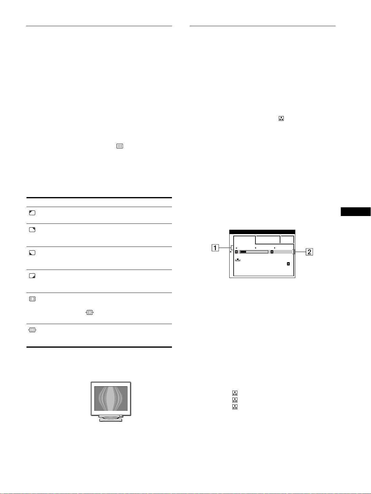
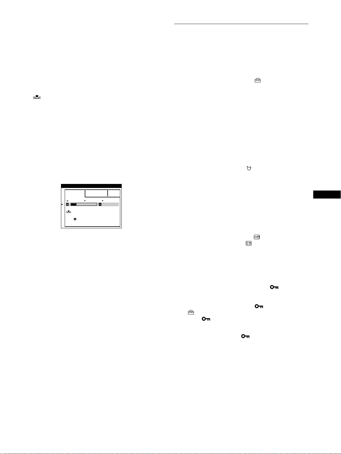
On-screen messages
the horizontal frequency is between 30 - 121 kHz, and the
GB
vertical frequency is between 48 - 160 Hz.
If there is something wrong with the input signal, one of the
following messages appears on the screen.
For more information, see “Trouble symptoms and remedies” on
If NO INPUT SIGNAL appears on the screen
page 18.
INFORMATION
Displaying this monitor’s name, serial number,
MON I TOR I S WORK I NG
HD15 :
and date of manufacture.
NO INPUT S IGNAL
While the monitor is receiving a video signal, press and hold the
joystick for more than three seconds to display this monitor’s
WH I T E
information box.
RED
GREEN
BLUE
Example
INFORMATION
1 The selected connector
MODEL
:
GDM F500R
b
SER NO
:
1234567
This message shows the currently selected connector
MANUFACTURED
: 1999-52
(HD15 or BNC).
2 The input signal condition
NO INPUT SINGAL
If the problem persists, call your authorized Sony dealer and give
This indicates that no signal is input, or that no signal is input
the following information.
from the selected connector.
• Model name: GDM-F500R
• Serial number
• Name and specifications of your computer and graphics board.
17

Trouble symptoms and remedies
If the problem is caused by the connected computer or other equipment, please refer to the connected equipment’s instruction manual.
Use the self-diagnosis function (page 20) if the following recommendations do not resolve the problem.
Symptom Check these items
No picture
If the 1 (power) indicator is not lit • Check that the power cord is properly connected.
• Check that the 1 (power) switch is in the “on” position.
If the NO INPUT SIGNAL message
• Check that the video signal cable is properly connected and all plugs are firmly seated in
appears on the screen, or if the
their sockets. If you are using the five BNC connectors, connect them in the correct order
1 (power) indicator is either orange
(from left to right: Red-Green-Blue-HD-VD) (page 6).
or alternating between green and
• Check that the INPUT switch setting is correct (page 9).
orange
• Check that the HD15 video input connector’s pins are not bent or pushed in.
x
Problems caused by the connected computer or other equipment
• The computer is in power saving mode. Try pressing any key on the computer keyboard.
• Check that the computer’s power is “on.”
• Check that the graphic board is completely seated in the proper bus slot.
If the OUT OF SCAN RANGE
x
Problems caused by the connected computer or other equipment
message appears on the screen
• Check that the video frequency range is within that specified for the monitor. If you
replaced an old monitor with this monitor, reconnect the old monitor and adjust the
frequency range to the following.
Horizontal: 30 – 121 kHz
Vertical: 48
–
160 Hz
If no message is displayed and the
• Use the Self-diagnosis function (page 20).
1 (power) indicator is green or
flashing orange
If using Windows 95/98 • If you replaced an old monitor with this monitor, reconnect the old monitor and do the
following. Install the supplied Setup Disk (page 7) and select this monitor
(“GDM-F500R”) from among the Sony monitors in the Windows 95/98 monitor selection
screen. If you choose to select “Plug and Play,” connect the monitor to the computer with
the HD15 video signal cable. You cannot use the five BNC connectors.
If using a Macintosh system • When connecting to a Power Macintosh G3 series computer that has three rows of pins,
check that the supplied G3 adapter and the video signal cable are properly connected
(page 6).
• For Power Macintosh G3 or other models which have two rows of pins, you will need a
different adapter which is sold separately.
Picture flickers, bounces,
• Isolate and eliminate any potential sources of electric or magnetic fields such as other
oscillates, or is scrambled
monitors, laser printers, electric fans, fluorescent lighting, or televisions.
• Move the monitor away from power lines or place a magnetic shield near the monitor.
• Try plugging the monitor into a different AC outlet, preferably on a different circuit.
• Try turning the monitor 90° to the left or right.
x
Problems caused by the connected computer or other equipment
• Check your graphics board manual for the proper monitor setting.
• Confirm that the graphics mode (VESA, Macintosh 21" Color, etc.) and the frequency of
the input signal are supported by this monitor (Appendix). Even if the frequency is within
the proper range, some video boards may have a sync pulse that is too narrow for the
monitor to sync correctly.
• Adjust the computer’s refresh rate (vertical frequency) to obtain the best possible picture.
Picture is fuzzy
• Adjust the brightness and contrast (page 11).
• Degauss the monitor* (page 15).
• If CANCEL MOIRE is ON, the picture may become fuzzy. Decrease the moire
cancellation effect or set CANCEL MOIRE to OFF (page 13).
18
Symptom Check these items
Picture is ghosting • Eliminate the use of video cable extensions and/or video switch boxes.
• Check that all plugs are firmly seated in their sockets.
Picture is not centered or sized
• Perform the AUTO function (page 9).
properly
• Adjust the size (page 11) or centering (page 12). Note that some video modes do not fill
the screen to the edges.
Edges of the image are curved • Adjust the geometry (page 12).
Wavy or elliptical pattern (moire)
• Set CANCEL MOIRE to ON and adjust the degree of moire cancellation until the moire is
is visible
at a minimum (page 13).
xProblems caused by the connected computer or other equipment
• Change your desktop pattern.
Color is not uniform • Degauss the monitor* (page 15). If you place equipment that generates a magnetic field,
such as a speaker, near the monitor, or if you change the direction the monitor faces, color
may lose uniformity.
• Adjust the landing (page 13).
White does not look white • Adjust the color temperature (page 13).
• Check that the five BNC connectors are connected in the correct order (from left to right:
Red-Green-Blue-HD-VD) (page 6).
Letters and lines show red or blue
• Adjust the convergence (page 12).
shadows at the edges
Monitor buttons do not operate
• If the control lock is set to ON, set it to OFF (page 15).
( appears on the screen)
IMAGE RESTORATION function
• Before using this function, the monitor must be in normal operation mode (green power
does not operate
indicator on) for at least 30 minutes. For more information on using the IMAGE
GB
RESTORATION function, see page 15.
COLOR
• Adjust the computer’s power saving settings to keep the monitor in normal operation
EASY EXPERT s BGR
mode for more than 30 minutes.
5000K 6500K 930 K0
• The monitor may gradually lose its ability to perform this function due to the natural aging
50 K00
of the picture tube.
IMAGE
RESTORATION
AVAI LABLE
AFTER WARM UP
USB peripherals do not function • Check that the appropriate USB connectors are securely connected (page 8).
• Check that the 1 (power) switch is in the “on” position.
xProblems caused by the connected computer or other equipment
• Check that the power of any self-powered USB compliant peripheral devices is “on.”
• Install the latest version of the device driver on your computer. Contact your device’s
manufacturer for information about the appropriate device driver.
• If your USB compliant keyboard or mouse does not function, connect them directly to
your computer, reboot your computer, and make any necessary adjustments to the USB
settings. Then reconnect the keyboard or mouse to the monitor.
• For customers using Windows 95
1. Right-click on My Computer and select Properties.
2. Click on the Device Manager tab. Scroll down and select Universal Serial Bus
Controller.
,If Universal Serial Bus Controller does not appear, you need to load a USB
supplement disk. Contact your computer’s manufacturer for more information about
obtaining a USB supplement disk.
3. Select Generic USB Device from the USB controller list and click on Properties.
4. If there is a check in the box next to “Disable in this hardware profile,” remove the
check.
5. Click on Refresh.
A hum is heard right after the
• This is the sound of the auto-degauss cycle. When the power is turned on, the monitor is
power is turned on
automatically degaussed for three seconds.
* If a second degauss cycle is needed, allow a minimum interval of 20 minutes for the best result. A humming noise may be heard, but this is not a
malfunction.
19
Self-diagnosis function
Specifications
This monitor is equipped with a self-diagnosis function. If there is
a problem with your monitor or computer(s), the screen will go
CRT 0.22 mm aperture grille pitch
blank and the 1 (power) indicator will either light up green or
21 inches measured diagonally
flash orange. If the 1 (power) indicator is lit in orange, the
90-degree deflection
computer is in power saving mode. Try pressing any key on the
FD Trinitron
keyboard.
Viewable image size Approx. 403.8 × 302.2 mm (w/h)
(16 × 12 inches)
19.8" viewing image
Resolution
RESET ASC INPUT MENUHD15 BNC
Maximum Horizontal: 2048 dots
Vertical: 1536 lines
Recommended Horizontal: 1600 dots
Vertical: 1200 lines
1
(power) indicator
Standard image area Approx. 388 × 291 mm (w/h)
3
1
(15
/
8
× 11
/
2
inches)
If the
1
(power) indicator is green
or
Approx. 364 × 291 mm (w/h)
1
Remove any plugs from the video input 1 and 2
3
1
(14
/
8
× 11
/
2
inches)
connectors, or turn off the connected computer(s).
Deflection frequency* Horizontal: 30 to 121 kHz
Vertical: 48 to 160 Hz
2
Press the
1
(power) button twice to turn the monitor
AC input voltage/current 100 to 240 V, 50 – 60 Hz, 2.0 – 1.0 A
off and then on.
Power consumption Approx. 145 W (with no USB devices
connected)
3
Move the joystick to the right
,
for 2 seconds
Operating temperature 10°C to 40°C
before the monitor enters power saving mode.
Dimensions
Approx. 502
×
511
×
480.3 mm (w/h/d)
7
1
1
(19
/
8
× 20
/
8
× 19
/
4
inches)
Mass Approx. 33 kg (72 lb 12 oz)
Plug and Play DDC1/DDC2B/DDC2Bi, GTF**
Supplied accessories See page 6
* Recommended horizontal and vertical timing condition
• Horizontal sync width duty should be more than 4.8% of
If all four color bars appear (white, red, green, blue), the monitor
total horizontal time or 0.8 µs, whichever is larger.
is working properly. Reconnect the video input cables and check
• Horizontal blanking width should be more than 2.3 µsec.
the condition of your computer(s).
• Vertical blanking width should be more than 450 µsec.
** If the input signal is Generalized Timing Formula (GTF)
If the color bars do not appear, there is a potential monitor failure.
compliant, the GTF feature of the monitor will automatically
Inform your authorized Sony dealer of the monitor’s condition.
provide an optimal image for the screen.
Design and specifications are subject to change without notice.
If the
1
(power) indicator is flashing orange
Press the
1
(power) button twice to turn the monitor off
and then on.
If the 1 (power) indicator lights up green, the monitor is working
properly.
If the 1 (power) indicator is still flashing, there is a potential
monitor failure. Count the number of seconds between orange
flashes of the 1 (power) indicator and inform your authorized
Sony dealer of the monitor’s condition. Be sure to note the model
name and serial number of your monitor. Also note the make and
model of your computer and video board.
20
