Panasonic AW-RP555: Parts and their functions
Parts and their functions: Panasonic AW-RP555
Parts and their functions
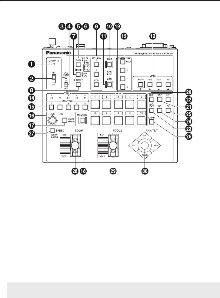
Control panel
OPERATE lamp
This lamp will come on when power is supplied to this unit and the OPERATE switch is
on.
OPERATE switch
This controls the power of all pan/tilt head systems (pan/tilt head and convertible
camera) connected to this unit. Allow at least 5 seconds between ON/OFF operations.
Setting the OPERATE switch to OFF will not turn the power to this unit off. To turn the
power to this unit completely off, the power switch of AC adapter must be turned off.
CAM CONT lamp
This lights when the CAM CONT switch is at ON and communication with the camera
of the pan/tilt head system currently selected is taking place successfully. It goes off if
trouble occurs in the communication.
When using a pan/tilt head other than the AW-PH350, AW-PH360 or AW-PH650, it
remains off even when communication is taking place successfully.
5 (E)

Parts and their functions
CAM CONT switch
This switch is used to turn the control panel’s camera control functions ON or OFF.
ENGLISH
ON: Camera control is enabled (turned on).
OFF: Camera control is disabled (turned off).
The following functions can be turned on and off using the CAM CONT switch.
GAIN, MODE, SHUTTER, WHT BAL [A, B, ATW], AWC, ABC, SCENE FILE [USER,
1, 2, 3], MENU/ , ITEM/ , YES/ , NO/
GAIN [AUTO/MANU] button
This is used to select the gain control mode of the camera in the pan/tilt head system
currently selected. Each time it is pressed, the mode is switched by one step in the
sequence of the auto mode and manual mode [0 dB, L (9 dB) and H (18 dB)].
If a setting other than 0 dB, 9 dB or 18 dB has been selected for the gain in the manual
mode using the camera menu, it will be changed to the setting established by the
operation of this button.
In the auto mode, the button’s lamp lights; in the manual mode, it goes off.
MANU [L, H] lamp
These lamps turn on and off as follows when a MANU gain setting has been selected
using the GAIN button.
0 dB L lamp off H lamp off
9 dB L lamp on H lamp off
18 dB L lamp off H lamp on
When a setting other than the above has been selected using the camera menu, both
the L and H lamps turn on.
MODE [BAR/CAM] button
This is used to select the camera’s video output signals in the pan/tilt head system
currently selected.
Each time it is pressed, the camera’s colour bar signals or video signals are selected in
turn.
When the colour bar signals are selected, the button’s lamp comes on; when the video
signals are selected, it goes off.
6 (E)

Parts and their functions
SHUTTER button
This is used to select the shutter speed of the camera in the pan/tilt head system
currently selected.
Each time the button is pressed, the set shutter speed is switched to shutter OFF or vice
versa.
The shutter speed is actually switched as soon as the button is released.
At any setting except OFF, the button’s lamp lights; at the OFF setting, it is off.
[How to register the shutter speed]
1. Press the SHUTTER button while holding down the MEMORY button.
2. The PRESET [1 to 5] buttons and PRESET [6 to 10] buttons start flashing alternately.
3. Press the PRESET button that corresponds to the shutter speed to be registered.
The table below lists the shutter speeds which can be set.
1/120 PRESET 1 1/4000 PRESET 6
1/250 PRESET 2 1/10000 PRESET 7
1/500 PRESET 3 SYNCHRO-SCAN PRESET 8
1/1000 PRESET 4 ELC PRESET 9
1/2000 PRESET 5 OFF PRESET 10
When OFF is set, the shutter will not be operated even when the SHUTTER button
is pressed.
Select the SYNCHRO-SCAN setting from the camera menu.
The change in the shutter speed is reflected when the shutter is next set to ON.
This setting is retained in the memory even after the control panel’s power has been
turned off.
[ When temporarily changing the shutter speed without registering it]
Press the PRESET button corresponding to the shutter speed to be set while holding
down the SHUTTER button.
Refer to the table above for the shutter speeds which can be set.
The shutter speed will be changed as soon as the PRESET button is pressed.
This setting will be cleared when either the shutter button is pressed or the camera’s
power is turned off.
7 (E)

Parts and their functions
WHITE BAL [A/B/ATW] buttons
These are used to select the camera’s white balance adjustment in the pan/tilt head
ENGLISH
system currently selected.
A: When the A button is pressed, the white balance status entered in the camera’s
memory A is established, and the A button’s lamp comes on.
If the AWC button is pressed after the A button was pressed, the white balance
is automatically adjusted and entered in the camera’s memory A.
B: When the B button is pressed, the white balance status entered in the camera’s
memory B is established, and the B button’s lamp comes on.
If the AWC button is pressed after the B button was pressed, the white balance
is automatically adjusted and entered in the camera’s memory B.
ATW: When the ATW button is pressed, the white balance is set to the automatic
adjustment mode, and the ATW button’s lamp comes on.
AWC button
When the WHITE BAL [A] button or [B] button has been selected, press the AWC button
to automatically adjust the white balance and enter the adjustment in the camera’s
memory A or memory B.
While the white balance is being adjusted, the AWC button’s lamp flashes; when it has
been adjusted properly, it goes off. It comes on when it was not possible to perform the
adjustment.
This function does not work if the MODE button has been set to BAR (the MODE
button’s lamp is lit) or if ATW has been selected.
It may not be possible to adjust the white balance if there is no white object on the
screen being shot.
When using a pan/tilt head other than the AW-PH350, AW-PH360 or AW-PH650,
the button’s lamp also goes off when the white balance has not been adjusted
properly.
8 (E)

Parts and their functions
ABC button
This is used to automatically adjust camera’s black balance in the pan/tilt head system
currently selected.
Set the IRIS [AUTO/MANU] button to AUTO (the IRIS button is now lit), and press the
ABC button.
While the black balance is being adjusted, the ABC button’s lamp flashes; when it has
been adjusted properly, it goes off. It comes on when it was not possible to perform the
adjustment.
No operations are performed when the MODE button has been set to BAR (the
MODE button’s lamp is lit).
When using a pan/tilt head other than the AW-PH350, AW-PH360 or AW-PH650,
the button’s lamp also goes off when the black balance has not been adjusted
properly.
SCENE FILE [USER/1/2/3] buttons
These are used to select the SCENE FILE of the camera in the pan/tilt head system
currently selected.
The lamp of the selected SCENE FILE button lights.
[ In the case of the AW-E350, AW-E650, AW-E655, AW-E750 and AW-E860]
When the [USER] button’s lamp lights, the user mode is selected.
When the [1] lamp lights, the halogen mode is selected.
When the [2] lamp lights, the fluorescent light mode is selected.
When the [3] lamp lights, the outdoor mode is selected.
MENU/ , ITEM/ , YES/ , NO/ buttons
These are used to display the on-screen menus of the camera in the pan/tilt head
system currently selected so that the settings can be performed on the menus.
When the MENU/ button is pressed for at least two seconds, the menu mode is
established, the on-screen menus are displayed in the camera video output, and the
MENU/ button lamp lights.
If the MENU/ button is pressed for at least two seconds in the menu mode, the menu
mode is exited, the on-screen menus in the camera video output are cleared, and the
MENU/ button lamp goes off.
For more details, refer to the “Setting and changing the camera menu items” (page 37).
TALLY lamps [1] to [5]
When tally signals are input to TALLY connectors [1] through [5], the lamps with the
numbers corresponding to the connectors come on.
9 (E)

Parts and their functions
CONTROL buttons [1] to [5]
Pressing buttons 1 to 5 will select the connected pan/tilt head system.
ENGLISH
When the AW-RC400 is connected, the button of the chosen number will illuminate and
the video signal from the selected pan/tilt head system will be output to the AW-RC400’s
MONITOR OUT 1 to 2 terminals.
IRIS LEVEL control
This is used to adjust the iris of the lens in the pan/tilt head system currently selected.
When the IRIS button is set to MANU, the control can move the lens iris all the way from
wide open to fully closed. When it is turned clockwise, the lens iris is opened; conversely,
when it is turned counterclockwise, it is closed.
When the IRIS button is set to AUTO, the control can be used to adjust the [Video level]
setting on the camera menu to adjust the focusing level of the automatic iris operation.
When it is turned clockwise, the lens iris is opened; conversely, when it is turned
counterclockwise, it is closed.
The lens iris is designed to be set only when the IRIS LEVEL control is moved.
With this control panel, the auto iris adjust function of the camera menu is
cancelled.
IRIS [AUTO/MANU] button
This is used to select how to adjust the lens iris of the pan/tilt head system currently
selected.
Each time it is pressed, the AUTO or MANU setting is selected in turn.
AUTO: The lens iris is adjusted automatically, and the IRIS button’s lamp comes on.
MANU: The lens iris is adjusted manually using the IRIS LEVEL control.
During this operation, the IRIS button lamp goes off.
MEMORY button
The lamp of this button goes off when communication has been established successfully
with the pan/tilt head system currently selected; it flashes when communication has
failed. If the lamp is flashing, check the power supply of the pan/tilt head system and the
cable connections.
Press the MEMORY button to register settings in the preset memories of the pan/tilt
head system or registering the limiter, shutter speed or other settings. For more details,
refer to the description of each function concerned.
PRESET buttons [1] to [10]
These are used to register the preset memory data in the buttons.
Preset memory data
: [1] to [10]
10 (E)

Parts and their functions
DEF button
This sets the defroster function ON or OFF when a pan/tilt head (AW-PH600/
AW PH650) equipped with a defroster function is used in the pan/tilt head system
currently selected.
Each time it is pressed, the function is turned ON or OFF in turn.
When the defroster is ON, the button’s lamp comes on; when it is OFF, the lamp goes
off.
WIP button
This sets the wiper function ON or OFF when a pan/tilt head (AW-PH600/AW-PH650)
equipped with a wiper function is used in the pan/tilt head system currently selected.
Each time it is pressed, the function is turned ON or OFF in turn.
When the wiper is ON, the button’s lamp comes on; alternatively, when it is OFF, it goes
off.
H/F button
This sets the heater/fan function ON or OFF when a pan/tilt head (AW-PH600/
AW PH650) equipped with a heater/fan function is used in the pan/tilt head system
currently selected.
Each time it is pressed, the function is turned ON or OFF in turn.
When the heater/fan is ON, the button’s lamp comes on; when it is OFF, the heater/fan
goes off.
EXT (AF) button
If a lens with an extender function is used in the selected pan/tilt head system, the
extender function is set from ON to OFF or vice versa each time the EXT (AF) button is
pressed.
If a lens (AW-LZ16AF7G) with an AF function is used in the selected pan/tilt head
system, the AF function of the lens is set from ON to OFF or vice versa each time the
EXT (AF) button is pressed.
In either case, the button lamp is lit at the ON setting, and it is extinguished at the OFF
setting.
This button can be used to turn the AF function ON or OFF only when the AW-PH350/
AW-PH360/AW-PH650 pan/tilt head is connected.
When the pan/tilt head is not used and only the camera is connected, select ON or
OFF using the menu item.
ND button
This sets the ND filter function ON or OFF when a lens equipped with an ND filter
function is used in the pan/tilt head system currently selected.
Each time it is pressed, the function is turned ON or OFF in turn.
When the ND filter is ON, the button’s lamp comes on; when it is OFF, the lamp goes off.
11 (E)

Parts and their functions
OP button
This controls the short- or open-circuiting of the OPTION SW CONTROL OUT
ENGLISH
connector of the AC adapter (AW-PS300A) which is connected to the pan/tilt head
system currently selected.
Each time it is pressed, short-circuiting or open-circuiting is selected in turn.
When the connector is short-circuited, the button’s lamp comes on; when it is open-
circuited, the lamp goes off.
LAMP button
This controls the ON and OFF of the halogen lamp which is connected to the pan/tilt
head system currently selected.
Each time it is pressed, the lamp is turned ON or OFF in turn.
When the halogen lamp is ON, the button’s lamp comes on; when it is OFF, the lamp
goes off.
It flashes when the halogen lamp has not been connected or when the lamp has been
disconnected or some other problem has occurred.
SPEED button
This is used to select the control (pan, tilt, zoom, focus, iris) speed of the pan/tilt head
system currently selected.
Each time it is pressed, the high-speed mode or low-speed mode is selected in turn.
The button’s lamp comes on in the low-speed mode, and it remains off in the high-speed
mode.
By pressing the SPEED button while holding down the MEMORY button, it is possible
to set whether the high-speed mode or low-speed mode is to be selected when the
power is turned on (or at OPERATE ON).
ZOOM lever
This is used to adjust the lens zoom in the pan/tilt head system currently selected.
Depending on the direction in which the ZOOM lever is tilted, TELE (telephoto) or WIDE
(wide angle) is set, and depending on the angle at which it is tilted, the zoom speed is
adjusted.
FOCUS lever
This is used to adjust the lens zoom in the pan/tilt head system currently selected. FAR
or NEAR is set by the direction in which the FOCUS lever is tilted, and the focus speed
is adjusted by the angle to which it is tilted.
12 (E)

Parts and their functions
PAN/TILT lever
This is used to adjust the direction of the pan/tilt head in the pan/tilt head system
currently selected.
When the PAN/TILT lever is panned in the L/R direction, the pan/tilt head direction
changes to the left or right; when it is tilted in the UP/DOWN direction, it changes in the
up or down direction.
The speed is adjusted by the angle to which the lever is tilted.
13 (E)
Parts and their functions
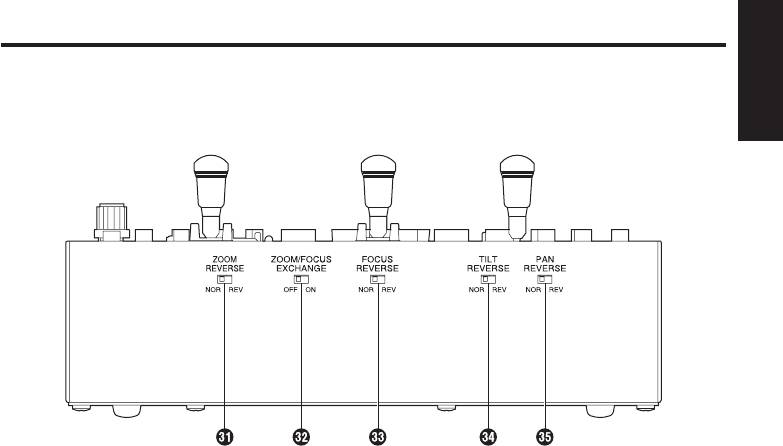
Front panel switches
ENGLISH
ZOOM REVERSE [NOR/REV] switch (Setting at shipment: NOR)
This is used to select the lens zoom operation which is to be performed by operating the
ZOOM lever.
When it is set to NOR, the zoom moves toward the telephoto end when the ZOOM
lever is tilted toward TELE or it moves toward the wide-angle end when the lever is tilted
toward WIDE.
When it is set to REV, the zoom operates in the reverse directions.
ZOOM/FOCUS EXCHANGE [ON/OFF]
switch (Setting at shipment: OFF)
This is used to select the ZOOM lever and FOCUS lever functions. When it is set to OFF,
the ZOOM lever adjusts the zoom operation of the lens, and the FOCUS lever adjusts its
focus operation.
When it is set to ON, the ZOOM lever adjusts the focus operation of the lens, and the
FOCUS lever adjusts its zoom operation.
FOCUS REVERSE [NOR/REV] switch (Setting at shipment: NOR)
This is used to select the lens focus operation which is to be performed by operating the
FOCUS lever.
When it is set to NOR, the point at which the lens is focused moves further away when
the FOCUS lever is tilted toward FAR, and it comes closer when the lever is tilted toward
NEAR.
When it is set to REV, focusing operates in the reverse directions.
14 (E)

Parts and their functions
TILT REVERSE [NOR/REV] switch (Setting at shipment: NOR)
This is used to select the operation of the pan/tilt head system in the vertical direction
(tilting) which is to be performed by operating the PAN/TILT lever.
When it is set to NOR, the pan/tilt head system moves upward when the PAN/TILT lever
is tilted toward UP, and it moves downward when the lever is tilted toward DOWN.
When it is set to REV, the tilting operates in the reverse directions.
Normally, set this switch to REV when using the AW-PH300 for the pan/tilt head
system in a stand-alone installation.
When the switch is set to REV, the pan/tilt head system moves upward when the
PAN/TILT lever is tilted toward UP, and it moves downward when the lever is tilted
toward DOWN.
PAN REVERSE [NOR/REV] switch (Setting at shipment: NOR)
This is used to select the operation of the pan/tilt head system in the horizontal direction
(panning) which is to be performed by operating the PAN/TILT lever.
When it is set to NOR, the pan/tilt head system moves toward the left when the PAN/
TILT lever is tilted toward LEFT, and it moves toward the right when the lever is tilted
toward RIGHT. When it is set to REV, the panning operates in the reverse directions.
Normally, set this switch to REV when using the AW-PH300 for the pan/tilt head
system in a stand-alone installation.
When the switch is set to REV, the pan/tilt head system moves toward the left when
the PAN/TILT lever is tilted toward LEFT and it moves toward the right when the lever
is tilted toward RIGHT.
15 (E)
Parts and their functions
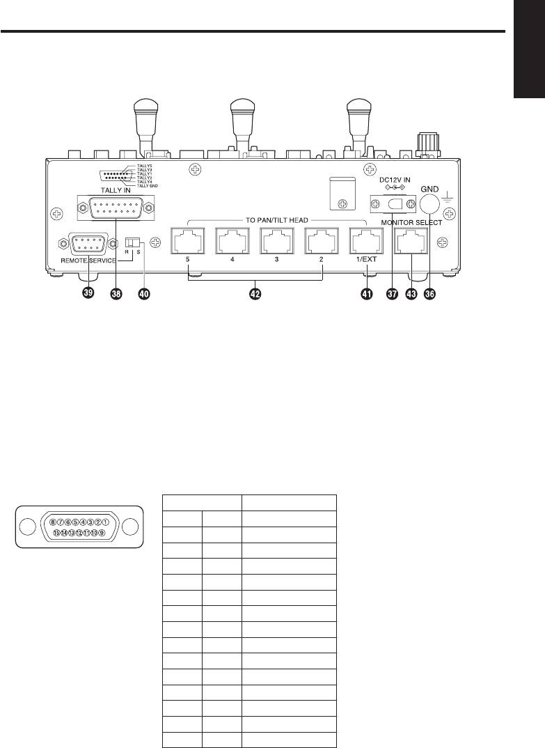
Rear connector panel
ENGLISH
GND terminal
Use to ground the unit.
DC12V IN terminal
Connects the AW-PS505A AC adapter (sold separately).
TALLY IN connector
Connect this to the TALLY connector on the video switcher or other units.
When the TALLY connector is set to the GND level, the TALLY lamp (
) lights. Do not
apply a voltage in excess of 5 V to this connector.
Pin No. Signal Name
1 TALLY1
9 TALLY2
2 TALLY3
Pin layout as seen from the
10 TALLY4
back of AW-RP555
3 TALLY5
11 TALLY GND
4 –––
12 –––
5 –––
13 –––
6 –––
14 –––
7 –––
15 –––
8 –––
16 (E)

Parts and their functions
REMOTE/SERVICE connector
A personal computer or other external equipment is connected here when a pan/tilt
head system is to be controlled by these equipments.
Pin No. Signal Name
1 –––
2 RXD IN
3 TXD OUT
4 DTR
5 GND
6 DSR
7 RTS
8 CTS
9 –––
REMOTE/SERVICE switch (Setting at shipment: R)
Function selection switch for the REMOTE/SERVICE connector. Set the switch in the “R”
position during use.
TO PAN/TILT HEAD 1/EXT terminal
• Functions as the pan/tilt head’s connection terminal 1 when the EXT CONTROL OUT
is set to OFF on the EXTERNAL CONTROL OUT setting (see page 24).
Connect a 10BASE-T straight cable (equivalent to UTP category 5) to the pan/tilt
head’s IP/RP terminal.
May be extended up to a maximum of 1,000 m.
Use the RS-232C/RS-422 converter and connect to pan/tilt head’s RS-232C control
terminal when connecting to the AW-PH300, AW-PH300A, AW-PH500 or AW-PH600.
• Functions as the AW-DU600 dial up adapter’s connection terminal when the EXT
CONTROL OUT is set to ON on the EXTERNAL CONTROL OUT setting (see
page 24).
Connect a 10BASE-T straight cable (equivalent to UTP category 5) to the AW-DU600’s
PAN/TILT CONTROL IN terminal. May be extended up to a maximum of 1,000 m.
For more details, refer to the operating instructions of the dial up adapter AW-DU600.
Use the following terms instead:
• AW-RP605
AW-RP555
• EXTERNAL CONTROL OUT terminal
TO PAN/TILT HEAD 1/EXT terminal
• There are no software version restrictions for this unit in systems with AW-DU600.
17 (E)

Parts and their functions
TO PAN/TILT HEAD 2 to 5 terminal
• Functions as the pan/tilt head’s connection terminals 2 to 5 when EXT CONTROL OUT
ENGLISH
is set to OFF on the EXTERNAL CONTROL OUT setting (see page 24).
Connect a 10BASE-T straight cable (equivalent to UTP category 5) to the pan/tilt
head’s IP/RP terminal.
May be extended up to a maximum of 1,000 m.
Use the RS-232C/RS-422 converter and connect to pan/tilt head’s RS-232C control
terminal when connecting to the AW-PH300, AW-PH300A, AW-PH500 or AW-PH600.
• Cannot be used when the EXT CONTROL OUT is set to ON on the EXTERNAL
CONTROL OUT setting (see page 24).
MONITOR SELECT terminal
Connect a 10BASE-T straight cable (equivalent to UTP category 5) to the AW-RC400
cable compensation unit’s MONI SEL IN terminal. May be extended up to a maximum of
50 m.
The video signal from the pan/tilt head system connected to the input terminal, whose
number is selected on this unit, will be sent from the AW-RC400’s MONITOR 1, 2
terminals.
18 (E)
Оглавление
- 规 格
- Contents
- Introduction
- Parts and their functions
- Connections
- Operation
- Setting and changing the camera menu items
- Attaching the rack mounting adapters
- How to change the position of the connector panel
- Appearance
- Specifications
- Inhalt
- Einleitung
- Teile und ihre Funktionen
- Anschlüsse
- Betrieb
- Einstellen und Ändern der Kameramenüposten
- Anbringen der Rackmontageadapter
- Ändern der Einbauposition der Anschlusstafel
- Aussehen
- Technische Daten
- Table des matières
- Introduction
- Les commandes et leurs fonctions
- Raccordements
- Utilisation
- Réglages et modifications des paramètres des menus de la caméra
- Fixation des adaptateurs de montage en rack
- Modification de la position du panneau des connecteurs
- Aspect extérieur
- Fiche technique
- Sommario
- Introduzione
- Parti e loro funzioni
- Collegamenti
- Operazioni
- Impostazione e modifica delle voci di menu della videocamera
- Utilizzo degli adattatori di montaggio su rack
- Modo di cambiare la posizione del pannello connettori
- Aspetto
- Dati tecnici
- Índice
- Introducción
- Partes y sus funciones
- Conexiones
- Funcionamiento
- Ajuste y cambio de los elementos de menú de la cámara
- Colocación de adaptadores de montaje en estantería
- Cambio de posición del panel de conectores
- Apariencia
- Especificaciones
- Содержание
- Введение
- Компоненты и их функции
- Соединения
- Эксплуатация
- Установка и изменение значений пунктов меню камеры
- Подключение адаптеров стоечного монтажа
- Как изменить положение панели разъемов
- Внешний вид
- Технические характеристики
- 目 录
- 产品介绍
- 附 件
- 部件及其功能
- 连 接
- 操 作
- 设置和更改摄像机菜单项目
- 安装架装适配器
- 如何改变接口面板的位置
- 外部尺寸图
- 规 格
