Panasonic AW-RC600: Parts and their functions
Parts and their functions: Panasonic AW-RC600
Parts and their functions
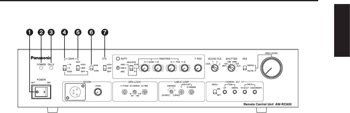
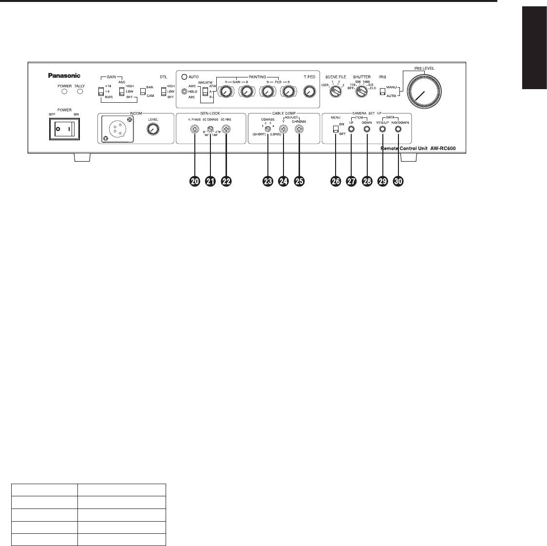
Front panel
ENGLISH
Power switch [POWER OFF/ON]
AGC selector switch [AGC HIGH/LOW/OFF]
ON: At this setting, the power is supplied to the unit
HIGH: At this setting, the maximum AGC gain is set to
(and the power indicator LED lights).
+30 dB. (This value may differ according to the
OFF: At this setting, the power is off.
camera used.)
LOW: At this setting, the maximum AGC gain is set to
Power indicator LED [POWER]
+18 dB. (This value may differ according to the
When the power switch is set to [ON], this LED lights up
camera used.)
green to indicate that the unit can be operated.
OFF: AGC does not function. Select the gain using the
gain increase selector switch
.
Tally indicator LED [TALLY]
Connect the unit’s tally/intercom input/output connector
Fine adjustment of AGC
with the TALLY & INCOM connector on the live switcher
If, when this switch is at the [HIGH] or [LOW] setting, the
(AW-SW350). This LED lights up red when the unit is
scene file switch
is set to [USER], [Auto iris adjust] is
selected using the controls on the live switcher.
set to [ON] on the camera menu and the lens iris selector
switch
is set to [AUTO], the AGC level can be finely
Gain increase selector switch
adjusted using the lens iris control
.
(For details on the camera menus, refer to the camera’s
[GAIN +18/+9/0(dB)]
operating instructions.)
This switch is operational only when the AGC selector
switch
is at the [OFF] setting.
When the AGC selector switch
is at the [LOW] or
Colour bar/camera selector switch [BAR/CAM]
[HIGH] setting, the gain will remain unchanged even
Set this switch to [BAR] to output colour bar signals.
when the setting of the gain increase selector switch is
Normally, it is used as the [CAM] setting.
switched.
The switch is normally used as the [0 dB] position. When
Detail compensation selector switch
shooting in dark locations and a sufficient video output
[DTL HIGH/LOW/OFF]
cannot be obtained even by setting the lens iris to wide
This switch is used to set the amount of detail
open, set it to [+9 dB] or [+18 dB].
compensation to HIGH, LOW or OFF. Select the preferred
setting.
4 (E)
Parts and their functions
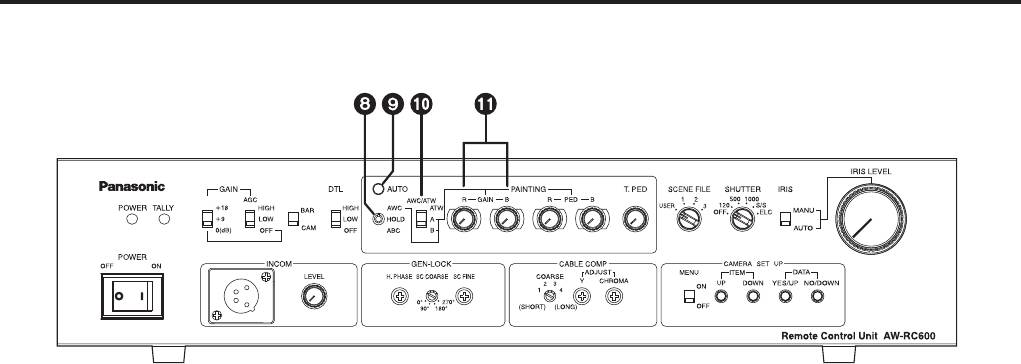
Auto white/auto black setting switch
White balance selector switch
[AWC/HOLD/ABC]
[AWC/ATW ATW/A/B]
Automatic adjustment of the white balance starts when
This switch is used to select the auto white balance
this switch is set to the top position while the white
setting.
balance selector switch
is at the [A] or [B] position.
ATW: At this setting, the camera provides
Regardless of the white balance selector switch
compensation in such a way that the white
setting, when the switch is set to the bottom position, the
balance is adjusted automatically even when the
lens iris closes and the automatic adjustment of the black
light source or colour temperature has changed.
balance starts.
The result is images in which nothing feels odd
The switch’s mechanism is designed to return the switch
or out of place.
to the [HOLD] setting when the switch is released, but the
Notes:
automatic adjustment continues until it is completed.
• This function may not operate properly
if a source of high brightness (such as a
Caution
fluorescent light) is shown on the screen.
The black balance cannot be adjusted properly unless
• The white balance may shift if there are no
the lens iris is completely closed.
white objects on the screen.
Automatic adjustment of the white balance and black
A or B: When the white balance is being automatically
balance is not performed when [BAR] has been selected
adjusted by the auto white/auto black setting
as the colour bar/camera selector switch
or when
switch
, the colour temperature conditions can
the camera’s menu is displayed due to the setting of the
be stored in memory [A] or [B].
menu ON/OFF switch
.
Red and blue gain adjustment controls
Auto setting indicator LED [AUTO]
[PAINTING GAIN R/B]
This LED starts blinking when the automatic adjustment
These controls enable the white balance to be adjusted
of the white balance or black balance is started by the
finely when the white balance selector switch
is at the
auto white/auto black setting switch
; it stops blinking
[A] or [B] setting.
and goes off when the adjustment ends successfully.
When the white balance is automatically adjusted again
If this LED is lit, it means that the adjustment has not
after it has been finely adjusted, it will return to the status
ended successfully.
prior to the fine adjustment regardless of the positions of
If the white balance has not ended successfully, change
these controls.
the lens iris setting, lighting, subject or other aspects, and
The function of the controls may be implemented in steps
try performing the automatic adjustment again.
since the processing involved uses digital signals: This is
If the black balance has not ended successfully, close
normal and does not indicate any malfunctioning.
the lens iris completely, and try performing the automatic
adjustment again.
5 (E)
Parts and their functions
ENGLISH
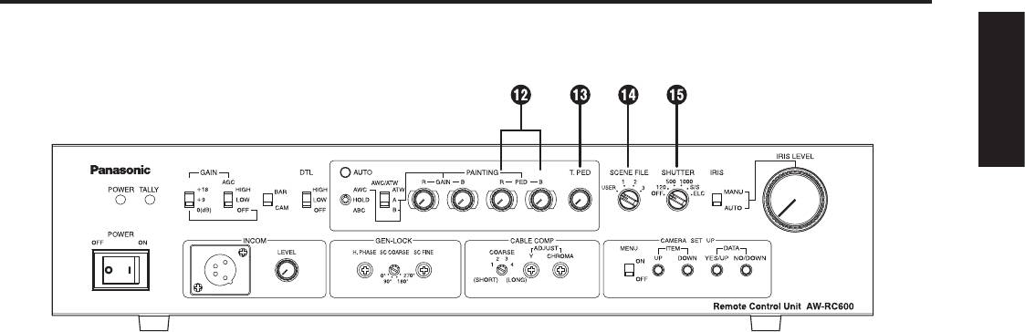
Red and blue pedestal adjustment controls
Electronic shutter selector switch
[PAINTING PED R/B]
[SHUTTER OFF/120/500/1000/ S/S /ELC]
These controls enable the black balance to be adjusted
This switch enables the shutter speed (OFF, 1/120, 1/500,
finely.
1/1000) as well as S/S and ELC to be selected.
When the black balance is automatically adjusted again
S/S: This stands for synchro scan. The shutter speed
after it has been finely adjusted, it will return to the status
can be varied continuously at this setting.
prior to the fine adjustment regardless of the positions of
(50.24 Hz to 15.63 kHz)
these controls.
Display the camera’s menu using the menu
The function of the adjustment controls may be
ON/OFF switch
, and set the shutter speed.
implemented in steps since the processing involved uses
(For details, refer to the camera’s operating
digital signals: This is normal and does not indicate any
instructions.)
malfunctioning.
ELC: At this setting, the electronic shutter is controlled,
and the light quantity is automatically adjusted.
Total pedestal adjustment control [T.PED]
Fine adjustment of ELC
This control enables the pedestal level of the video
ELC can be finely adjusted using the lens iris control
signals to be adjusted. It is used when, for instance, the
by setting the scene file switch
to [USER], setting
pedestal level of two or more cameras is to be adjusted.
[Auto iris adjust] to [ON] using the camera’s menu and
The function of the control may be implemented in steps
setting the lens iris selector switch
to [AUTO] when this
since the processing involved uses digital signals: This is
switch is at [ELC].
normal and does not indicate any malfunctioning.
(For details of the camera menus, refer to the camera’s
operating instructions.)
Scene file switch [USER/1/2/3]
This switch is used to select the camera’s scene files.
Note:
USER: USER mode
Smear may appear with high-brightness subjects when
1: Halogen light mode
the electronic shutter selector switch is set to ELC.
2: Fluorescent light mode
3: Outdoor mode
Select the scene file which is optimally suited to the
shooting conditions.
(For details, refer to the camera’s operating instructions.)
6 (E)
Parts and their functions
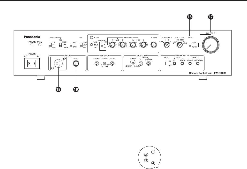
Lens iris selector switch [IRIS MANU/AUTO]
Intercom connector [INCOM]
The lens is set to automatic iris (ALC) if this switch is set
(XLR 4-pin connector)
to [AUTO] when the iris selector switch on the lens is at
A headset is connected here. Intercommunication is then
[AUTO]. The lens iris can now be finely adjusted using
possible between the camera, RCU and live switcher.
the lens iris control
by setting the scene file switch
Set the INCOM selector switch on the live switcher
to [USER] and setting [Auto iris adjust] to [ON] using the
(AW-SW350) to the [3-wire type].
camera’s menu in this status.
(For details of the camera menus, refer to the camera’s
1: GND
operating instructions.)
2: MIC (this is where the headset
When the switch is set to [MANU], the lens iris can be
microphone is connected)
adjusted manually from closed to wide open using the
3: GND
lens iris control
.
4: SPEAKER (this is where the headset
speaker is connected)
Lens iris control [IRIS LEVEL]
ALC (AGC and ELC) can be finely adjusted by setting
Use a dynamic type of microphone with an impedance
the lens iris selector switch
to [AUTO], the scene file
of approximately 200 ohms for the headset to be
switch
to [USER], and [Auto iris adjust] to [ON] using
connected.
the camera’s menu.
Recommended headset:
When the lens iris selector switch
is set to [MANU], the
HRM-201D (Ashida Sound Co., Ltd)
lens iris can be adjusted manually from closed to wide
CC-26K (CLEAR-COM)
open.
Intercom volume adjustment control
Note:
[INCOM LEVEL]
The ALC cannot be finely adjusted and the lens iris
This is used to adjust the volume of the sound heard
cannot be adjusted when the iris selector switch on
through the speaker of the headset connected to the
the lens is set to a position other than [AUTO] (such as
INCOM connector.
[MANU]).
With some lenses, the open and close directions with
respect to the control directions may be reversed. If this is
the case, contact the lens manufacturer or your dealer.
7 (E)
Parts and their functions
ENGLISH
Horizontal phase adjustment control [H.PHASE]
Chroma gain adjustment control
This is used to adjust the horizontal phases of the
[ADJUST CHROMA]
gen-lock input and video output when two or more
This is used to adjust the chrominance level of the video
cameras are used at the same time.
output signals to match the cable length.
(Select the cable length using the cable compensation
Subcarrier phase coarse adjustment switch
selector switch
and adjust the Y level of the video
[SC COARSE]
output signals using the Y gain adjustment control
This is used to adjust the hue of the gen-lock input and
before adjusting the level.)
video output coarsely when two or more cameras are
used at the same time. When used in combination with
Menu ON/OFF switch [MENU OFF/ON]
the subcarrier phase fine adjustment control
, the
OFF: Only the camera’s images are output to the video
adjustable range is greater than 360 degrees.
output.
ON: The camera’s images and superimposed camera’s
Subcarrier phase fine adjustment control
menu are output to the video output.
[SC FINE]
Menu items can be selected and data changed using
This is used to adjust the hue of the gen-lock input
the item UP switch
, item DOWN switch , DATA
and video output finely when two or more cameras are
YES/UP switch
and DATA NO/DOWN switch .
used at the same time. When used in combination with
For details on the menu items and contents, refer to
the subcarrier phase coarse adjustment switch
, the
the camera’s operating instructions.
adjustable range is greater than 360 degrees.
Item UP switch [ITEM UP]
Cable compensation selector switch [COARSE]
When this is pressed while a menu is displayed, the item
This is set in line with the length of the cable between the
which is the next one up from the current item on the
camera and RCU.
menu can be selected.
Switch position Cable length
Item DOWN switch [ITEM DOWN]
1 Less than 75 m
When this is pressed while a menu is displayed, the item
2 75 to 150 m
which is the next one down from the current item on the
menu can be selected.
3 150 to 230 m
4 230 to 300 m
DATA YES/UP switch [DATA YES/UP]
(The cable lengths above are approximations only.)
When this is pressed while the main menu is displayed,
the submenus of the items are displayed.
Y gain adjustment control [ADJUST Y]
When it is pressed while a submenu is displayed, the
This is used to adjust the Y (luminance) level of the video
setting is incremented.
output signals to match the cable length.
(Select the cable length using the cable compensation
DATA NO/DOWN switch [DATA NO/DOWN]
selector switch
before adjusting the level. The chroma
When this is pressed while the main menu is displayed,
amount is also varied by this control.)
the item which is the next one down from the current item
on the menu can be selected.
When it is pressed while a submenu is displayed, the
setting is decremented.
8 (E)
Parts and their functions
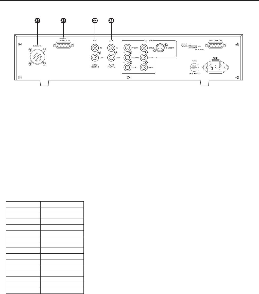
Rear panel
Camera cable connector [CAMERA]
Ensure that both the LEFT and RIGHT pins are not
(26-pin connector)
connected to the COMM pin at the same time.
The camera’s cable (such as the AW-CA50A26) is
Similarly, do not connect both the UP and DOWN, FAR
connected here.
and NEAR or WIDE and TELE pins to the COMM pin
at the same time.
Contact-type pan/tilt head control connector
Pins #12 to #15 are used when exercising lens control
only. To do this, connect the controller’s FOCUS CONT
[PAN/TILT CONTROL IN]
pin to NEAR (pin #6) and its ZOOM CONT pin to WIDE
(D-SUB 15-pin connector)
(pin #8). (Normally, pins #12 to #15 are not used when
This has the same shape as the tally/intercom input/
exercising control by contacts.)
output connector. Take care not to confuse the two
when connecting them.
A controller for controlling the lens (a lens with zoom
Gen-lock input/output connector
and focus servo) and pan/tilt head (up, down, left,
[G/L IN/OUT]
right, defroster, wiper, etc.) is connected here. (Only a
(75-ohm automatic termination)
contact-type controller can be connected.)
The external sync signals (black burst signals or
composite signals) from another system are connected
Pin No. Signal Name
here.
1 LEFT
2 RIGHT
Note:
3 UP
The input signals must be connected to the BNC
4 DOWN
connector marked “IN” (75-ohm automatic termination).
5 FAR
If it is connected to the BNC connector marked “OUT,” a
6 NEAR
high-impedance state will result, and the connector will
7 TELE
not be terminated by the 75-ohm resistance.
8 WIDE
9 DEFROSTER
AUX signal input/output connector
10 WIPER
[AUX IN/OUT] (75-ohm automatic termination)
11 COMM
Connect the line view signals from a live switcher or other
12 +5 V
device here.
13 +V (+7.5 V)
Note:
14 –V (+2.5 V)
The input signals must be connected to the BNC
15 GND
connector marked “IN” (75-ohm automatic termination).
If it is connected to the BNC connector marked “OUT,” a
The optional board must be installed in the camera in
high-impedance state will result, and the connector will
order to use a contact-type pan/tilt head. For details,
not be terminated by the 75-ohm resistance.
refer to the camera’s operating instructions.
When the control pins (#1 to #10) are connected to the
COMM pin (#11), the control signals are sent from the
RCU to the camera.
When the controller is to be fabricated, connect a
resistor with a resistance of 1 to 10 kilohms (1/8 W or
more) between the COMM pin and +5 V pin.
9 (E)
Parts and their functions
ENGLISH
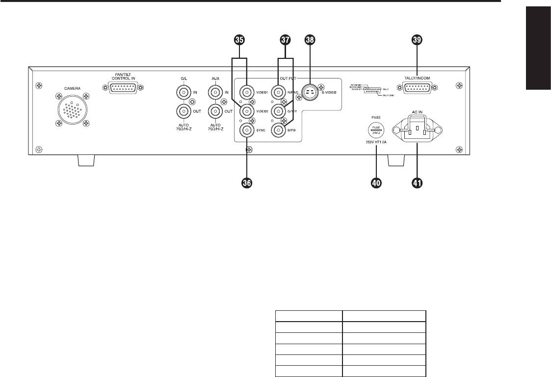
Video output connectors [VIDEO1, VIDEO2]
Tally/intercom input/output connector
The video signals from the camera after cable
[TALLY/INCOM] (D-SUB 15-pin connector)
compensation are output from these connectors. (The
Connect this to the TALLY & INCOM connector on the live
same signal is output from connectors 1 and 2.)
switcher (AW-SW350).
Connect the connectors to the video input connectors
Set the INCOM selector switch on the live switcher
on the live switcher, colour monitor, VTR or other device.
(AW-SW350) to [3-wire type].
(Output impedance: 75 ohms)
When inputting the tally control signals from another
device, input them with 0 V for ON and open for OFF.
SYNC output connector [SYNC]
Pin No. Signal Name
The composite sync signal is output from this connector.
1 TALLY
Connect the connector to the gen-lock input connector on
6 INCOM MIC
the colour monitor or other device.
7 INCOM GND
(Output impedance: 75 ohms)
8 INCOM SP
11 TALLY GND
RGB/Y, PR and PB/YC output connectors
[R/PR/C, G/Y/Y, B/PB]
If a camera such as the AW-E650 with RGB/Y, PR and
Fuse holder [FUSE]
PB/YC signal output facilities is connected to the remote
Fuse used: HT1AN5 (AC 250 V, 1 A)
control unit, its signals are output from these connectors.
(Output impedance: 75 ohms)
AC power socket [AC IN]
The RGB/Y, PR or PB/YC signals are selected using
Attach one end of the power cord provided to this socket
the camera’s menu. (For details, refer to the camera’s
and the other end to the AC 220 to 240 V (50 Hz) power
operating instructions.)
supply.
S-Video output connector [S-VIDEO OUT]
(4-pin S-connector)
The same signals as the ones output from the R/PR/C
and G/Y/Y connectors among the RGB/Y, PR and PB/YC
output connectors are output from this connector.
(Output impedance: 75 ohms)
The YC signals are selected using the camera’s menu,
and connected to a colour monitor or other device
equipped with an S-Video input connector.
Note:
When the RGB/Y, PR and PB/YC output connectors
and S-Video output connector are used at the same
time, the level of the output signals will be reduced.
Therefore, use either connectors
or connector in
line with the connectors used on the device connected to
the remote control unit.
10 (E)
Оглавление
- Safety precautions
- Contents
- Precautions for use
- Parts and their functions
- Connections
- Operating procedure
- Adjustment
- Menu item setting
- Rack mounting
- Appearance
- Specifications
- Sicherheitshinweise
- Inhalt
- Vorsichtsmaßnahmen zum Gebrauch
- Teile und ihre Funktionen
- Anschlüsse
- Bedienungsverfahren
- Einstellung
- Einstellung von Menüposten
- Rack-einbau
- Aussehen
- Technische Daten
- Consignes de sécurité
- Table des matières
- Précautions d’utilisation
- Les commandes et leurs fonctions
- Raccordements
- Utilisation
- Réglages
- Réglage des options du menu
- Installation en rack
- Aspect extérieur
- Fiche technique
- Precauzioni per la sicurezza
- Sommario
- Precauzioni per l’uso
- Parti e loro funzioni
- Collegamenti
- Funzionamento
- Regolazioni
- Configurazione delle voci di menu
- Montaggio su rack
- Aspetto
- Dati tecnici
- Precauciones de seguridad
- Índice
- Precauciones para la utilización
- Partes y sus funciones
- Conexiones
- Procedimiento de operación
- Ajuste
- Ajuste de los elementos del menú
- Montaje en estantería
- Apariencia
- Especificaciones
- Меры предосторожности
- Содержание
- Меры предосторожности во время использования
- Компоненты и их функции
- Соединения
- Рабочая процедура
- Регулировка
- Установка пунктов меню
- Монтаж в стойку
- Внешний вид
- Технические характеристики
- Safety precautions
