Panasonic EY7541: III
III: Panasonic EY7541
original options and sockets to the
square drive on the body. The cushion
rubber in the square drive to push up
the ball may get hard under freezing
point. This requires extra force in
detaching and attaching sockets.
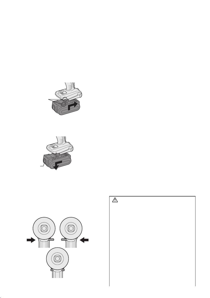
Attaching or Removing Bat-
tery Pack
1. To connect the battery pack:
Line up the alignment marks and attach
the battery pack.
•
Slide the battery pack until it locks into
position.
Alignment
marks
2. To remove the battery pack:
Push on the button from the front to re-
lease the battery pack.
Button
III
. OPERATION
[Main Body]
Switch and Forward/Reverse
Lever Operation
-
6
-
Forward Reverse
Switch lock
CAUTION:
To prevent damage, do not operate
Forward/Reverse lever until the bit
comes to a complete stop.
Forward Rotation Switch
Operation
1. Push the lever for forward rotation.
2. Depress the trigger switch slightly to start
the tool slowly.
3. The speed increases with the amount of
depression of the trigger for efficient tight-
ening of screws. The brake operates and
the bit stops immediately when the trigger
is released.
4. After use, set the lever to its center posi
-
tion (switch lock).
Reverse Rotation Switch
Operation
1.
Push the lever for reverse rotation. Check
the
direction of rotation before use.
2.
Depress the trigger switch slightly to start the
tool slowly.
3. After use, set the lever to its center posi-
tion (switch lock).
CAUTION:
• To eliminate excessive temperature
increase of the tool surface, do not
operate the tool continuously using two
or more battery packs. Tool needs cool
off time before switching to another
pack.
How to Use the Belt Hook
WARNING!
• Be sure to attach the belt hook securely
to the main unit with the screw firmly fas-
tened. When the belt hook is not firmly
attached to the main unit, the hook may
disconnect and the main unit may fall.
This may result in an accident or injury.
• Periodically check screw for tightness. If
found to be loose, tighten firmly.
•
Be sure to attach the belt hook firmly and
securely onto a waist belt or other belt. Pay
attention that the unit does not slip off the
belt.
This may result in an accident or injury.
• When the main unit is held by the belt
hook, avoid jumping or running with it.
Doing so may cause the hook to slip and
the main unit may fall.
This may result in an accident or injury.
• When the belt hook is not used, be sure
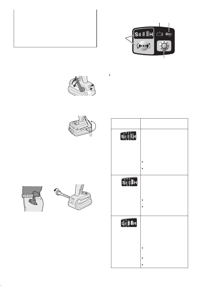
Control Panel
to return it to the storing position. The belt
(4) (3)
hook may catch on something.
This may result in an accident or injury.
•
When the unit is hooked onto the waist belt
by the belt hook, do not attach driver bits
(1)
to the unit. A sharp edge object, such as a
drill bit, may cause injury or an accident.
To Set the Belt Hook Angle
(2)
Position
1. Slide the belt hook lock lever 1 and hold
(1) Impact Power Mode Select
it to unlock the belt hook.
Selecting the impact power among 3
2
2. Pull the belt hook from
modes (Soft, Medium, Hard).
1
storing position 2 and
Press the impact power mode button to set
set it.
it. The mode changes to hard, medium, or
3.
Release the belt hook
3
soft each time the button is pressed.
lock lever to
lock the
The driver is preset to “hard” impact mode
angle of belt hook.
setting when shipped from the manufac-
4.
Make sure the belt hook is firmly locked.
turer.
Also make sure the belt hook is firmly
Recommended work guideline table
locked into position
3
.
Impact
• The belt hook cannot
Power mode
Recommended Application
be locked in this posi-
Display
tion. Firmly lock it into
Jobs requiring a high level
position before use.
of torque where there is
H
no possibility of the bolts
To return the belt hook to the storing position,
or screw breaking, its top
Follow step 1. and 2. above, then lower the
shearing off, or the bit coming
belt hook.
loose. (This setting provides
0 – 2300 r.p.m.
To secure the lock, follow 3 and 4 above.
maximum torque.) Suitable
and
applications include:
0 – 3000 i.p.m.
Tightening M8 and larger
To Change the Belt Hook
bolts
Tightening long screws
Location Side
during interior finishing work
The belt hook can be attached to either
Jobs requiring limited torque
side of the unit.
where there is a possibility of
M
the screw breaking or its top
shearing off. (This setting limits
torque.) Suitable applications
include:
0 – 1400 r.p.m.
Tightening bolts with
and
smaller diameters (M6)
0 – 2800 i.p.m.
Tightening metalwork
screws when installing
fixtures
1. Set the belt hook at storing position.
Jobs requiring limited torque
2. Loosen the screw turning it counter-
where there is a possibility
S
clockwise, using a flat metal or a flat
of the screw breaking, its
top shearing off, or the bit
blade screw driver.
coming loose and damaging
3. Take out the belt hook and insert into
anishedexteriorsurface.
the other side of the slot on the main
(This setting limits torque.)
0 – 1000 r.p.m.
unit.
Suitable applications include:
and
Tightening bolts smaller
4. Fasten the screw firmly, turning it clock
-
0 – 2000 i.p.m.
than M6 that may shear
wise.
easily
Tightening screws into
The belt hook can be taken out from the
molded plastic
main unit only when it is at storing posi-
Installing gypsum wallboard
tion.
* i.p.m. = Impact per minute.
-
7
-
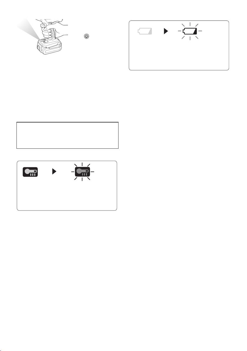
(2) LED light
(4) Battery low warning lamp
Before the use of LED
light, always pull the
power switch once.
Press the LED light
on button.
The light illuminates
Off (normal
Flashing (No charge)
operation)
with very low cur-
Battery protection
rent, and it does not
feature active
adversely affect the performance of the tool
during use or its battery capacity.
Excessive (complete) discharging of Li-
CAUTION:
ion batteries shortens their service life
• The built-in LED light is designed to illu-
dramatically. The driver includes a battery
minate the small work area temporarily.
protection feature designed to prevent
•
Do not use it as a substitute for a regular
excessive discharging of the battery pack.
flashlight, since it does not have enough
• The battery protection feature activates
brightness.
immediately before the battery loses its
•
LED light turns off when the tool has not
charge, causing the battery low warning
been used for 5 minutes.
lamp to flash.
Caution : DO NOT STARE INTO BEAM.
• If you notice the battery low warning
lamp flashing, charge the battery pack
Use of controls or adjustments or performance
immediately.
ofproceduresotherthanthosespeciedherein
may result in hazardous radiation exposure.
[Battery Pack]
(3) Overheat warning lamp
For Appropriate Use of Bat-
tery Pack
Li-ion Battery Pack (EY9L40/
Off (normal
Flashing: Overheat
EY9L41)
operation)
Indicates operation has
• For optimum battery life, store the Li-ion
been halted due to motor
battery pack following use without charging
or battery overheating.
it.
The overheating protection feature halts
• When charging the battery pack, confirm
driver operation to protect the motor and
that the terminals on the battery charger
battery pack in the event of overheating.
are free of foreign substances such as
The overheat warning lamp on the control
dust and water etc. Clean the terminals
panel flashes when this feature is active.
before charging the battery pack if any
•
If the overheating protection feature acti-
foreign substances are found on the ter-
vates, allow the driver to cool thoroughly
minals.
(at least 30 minutes). The driver is ready
The life of the battery pack terminals may
for use when the overheat warning lamp
be affected by foreign substances such as
goes out.
dust and water etc. during operation.
•
Avoid using the driver in a way that
• When battery pack is not in use, keep it
causes the overheating protection fea-
away from other metal objects like: paper
ture to activate repeatedly.
clips, coins, keys, nails, screws, or other
small metal objects that can make a con-
nection from one terminal to another.
Shorting the battery terminals together
may cause sparks, burns or a fire.
•
When operating the battery pack, make
sure the work place is well ventilated.
-
8
-
• When the battery pack is removed from the
CAUTION:
main body of the tool, replace the battery
To prevent the risk of fire or damage to
pack cover immediately in order to prevent
the battery charger.
dust or dirt from contaminating the battery
• Do not use power source from an
terminals and causing a short circuit.
engine generator.
• Do not cover vent holes on the charger
and the battery pack.
• Unplug the charger when not in use.
Li-ion Battery Pack
NOTE:
Battery Pack Life
Your battery pack is not fully charged at
The rechargeable batteries have a lim-
the time of purchase. Be sure to charge
ited life. If the operation time becomes
the battery before use.
extremely short after recharging, replace
the battery pack with a new one.
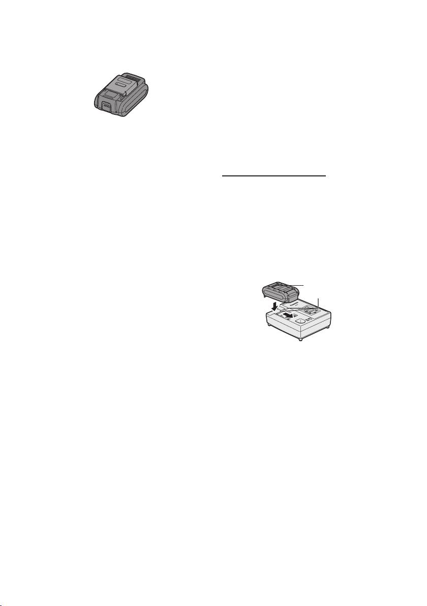
Battery charger (EY0L80)
1. Plug the charger into the AC outlet.
Battery Recycling
NOTE:
ATTENTION:
Sparks may be produced when the plug
For environmental protection and recy-
is inserted into the AC power supply, but
cling of materials, be sure that it is dis-
this is not a problem in terms of safety.
posed of at an officially assigned loca-
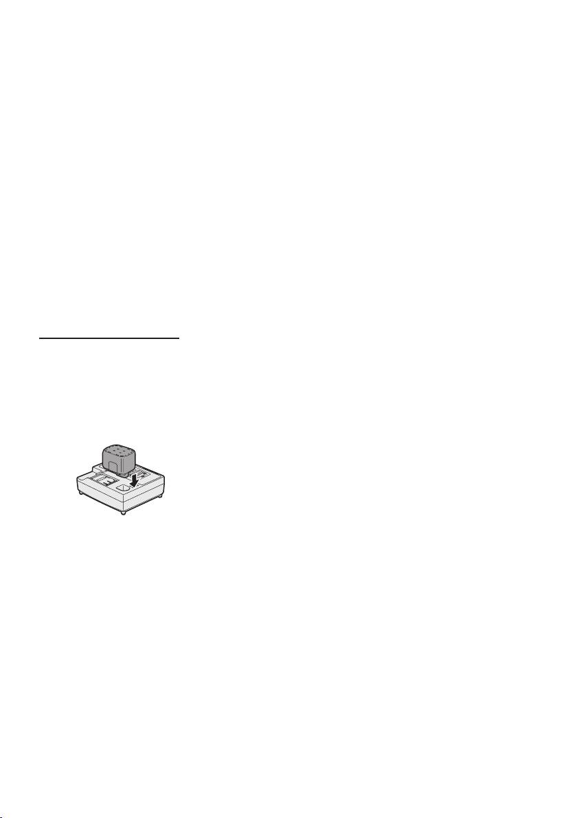
2.
Insert the battery pack firmly into the charger.
tion, if there is one in your country.
1 Line up the alignment marks and place the
battery onto the dock on the charger.
[Battery Charger]
2 Slide forward in the direction of the arrow.
Alignment marks
Charging
Cautions for the Li-ion Battery
Pack
• If the temperature of the battery pack falls
approximately below −10°C (14°F),charg
-
3.
During charging, the charging lamp will be
ing will automatically stop to prevent degra-
lit.
dation of the battery.
When charging is completed, an internal
electronic switch will automatically be trig-
Common Cautions for the Li-
gered to prevent overcharging.
ion/Ni-MH/Ni-Cd Battery Pack
• Charging will not start if the battery
• The ambient temperature range is between
pack is warm (for example, immediately
0°C (32°F) and 40°C (104°F).
after heavy-duty operation).
If the battery pack is used when the bat
-
The orange standby lamp will be flash
-
tery temperature is below 0°C (32°F),
ing until the battery cools down.
the tool may fail to function properly.
Charging will then begin automatically.
• When charging a cool battery pack (below
4.
The charge lamp (green) will flash slowly
0°C (32°F)) in a warm place, leave the
once the battery is approximately 80%
battery pack at the place and wait for
charged.
more than one hour to warm up the bat-
5.
When charging is completed, the charging
tery to the level of the ambient tempera-
lamp will start flashing quickly in green color.
ture.
6. If the temperature of the battery pack is
•
Cool down the charger when charging more
0°C or less, charging takes longer to fully
than two battery packs consecutively.
charge the battery pack than the standard
• Do not insert your fingers into contact
charging time.
hole, when holding charger or any other
occasions.
-
9
-
Even when the battery is fully charged, it
5.
If the charging lamp does not light imme-
will have approximately 50% of the power
diately after the charger is plugged in, or if
of a fully charged battery at normal operat-
after the standard charging time the charg-
ing temperature.
ing lamp does not flash quickly in green,
consult an authorized dealer.
7.
If the power lamp does not light immediately
after the charger is plugged in, or if after the
6. If a fully charged battery pack is inserted
standard charging time the charging lamp
into the charger again, the charging lamp
does not flash quickly in green, consult an
lights up. After several minutes, the charg-
authorized dealer.
ing lamp may flash quickly to indicate the
charging is completed.
8. If a fully charged battery pack is inserted
into the charger again, the charging lamp
lights up. After several minutes, the charg-
ing lamp may flash quickly to indicate the
charging is completed.
Ni-MH/Ni-Cd Battery Pack
NOTE:
When you charge the battery pack for
the first time, or after prolonged stor-
age, charge it for about 24 hours to
bring the battery up to full capacity.
Battery charger (EY0L80)
1. Plug the charger into the AC outlet.
NOTE:
Sparks may be produced when the plug
is inserted into the AC power supply, but
this is not a problem in terms of safety.
2.
Insert the battery pack firmly into the charger.
3.
During charging, the charging lamp will be
lit.
When charging is completed, an internal
electronic switch will automatically be trig-
gered to prevent overcharging.
• Charging will not start if the battery
pack is warm (for example, immediately
after heavy-duty operation).
The orange standby lamp will be
flashing until the battery cools down.
Charging will then begin automatically.
4.
When charging is completed, the charg-
ing lamp will start flashing quickly in green
color.
-
10
-
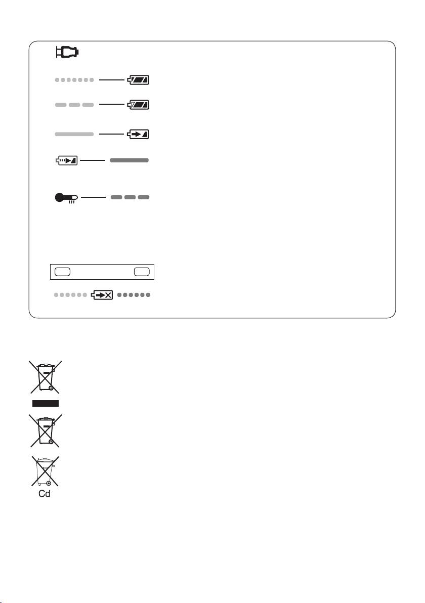
LAMP INDICATIONS
Green Lit
Charger is plugged into the AC outlet.
Ready to charge.
Green Flashing Quickly
Charging is completed. (Full charge.)
Green Flashing
Battery is approximately 80% charged (Usable charge. Li-ion
only).
Green Lit
Now charging
Orange Lit
Battery pack is cool.
The battery pack is being charged slowly to reduce the load on
the battery. (Li-ion only)
Orange Flashing
Battery pack is warm. Charging will begin when temperature of
battery pack drops.
If the temperature of the battery pack is −10°C or less, the
chargingstatuslamp(orange)willalsostartashing.Charg
-
ing will begin when the temperature of the battery pack goes
up (Li-ion only).
Charging Status Lamp
Left: green Right: orange will be displayed.
Both Orange and Green Flashing Quickly
Charging is not possible. Clogged with dust or malfunction of
the battery pack.
Information for Users on Collection and Disposal of Old Equip-
ment and used Batteries
These symbols on the products, packaging, and/or accompanying documents mean
that used electrical and electronic products and batteries should not be mixed with
general household waste.
For proper treatment, recovery and recycling of old products and used batteries, please
take them to applicable collection points, in accordance with your national legislation
and the Directives 2002/96/EC and 2006/66/EC.
By disposing of these products and batteries correctly, you will help to save valuable
resources and prevent any potential negative effects on human health and the
environment which could otherwise arise from inappropriate waste handling.
For more information about collection and recycling of old products and batteries,
please contact your local municipality, your waste disposal service or the point of sale
where you purchased the items.
Penalties may be applicable for incorrect disposal of this waste, in accordance with
national legislation.
For business users in the European Union
If you wish to discard electrical and electronic equipment, please contact your dealer or
supplier for further information.
-
11
-
[Information on Disposal in other Countries outside the European
Union]
These symbols are only valid in the European Union. If you wish to discard these items,
please contact your local authorities or dealer and ask for the correct method of disposal.
Note for the battery symbol (bottom two symbol examples):
This symbol might be used in combination with a chemical symbol. In this case it complies
with the requirement set by the Directive for the chemical involved.
IV
. MAINTENANCE
Use only a dry, soft cloth for wiping the unit. Do not use a damp cloth, thinner, benzine, or other
volatile solvents for cleaning.
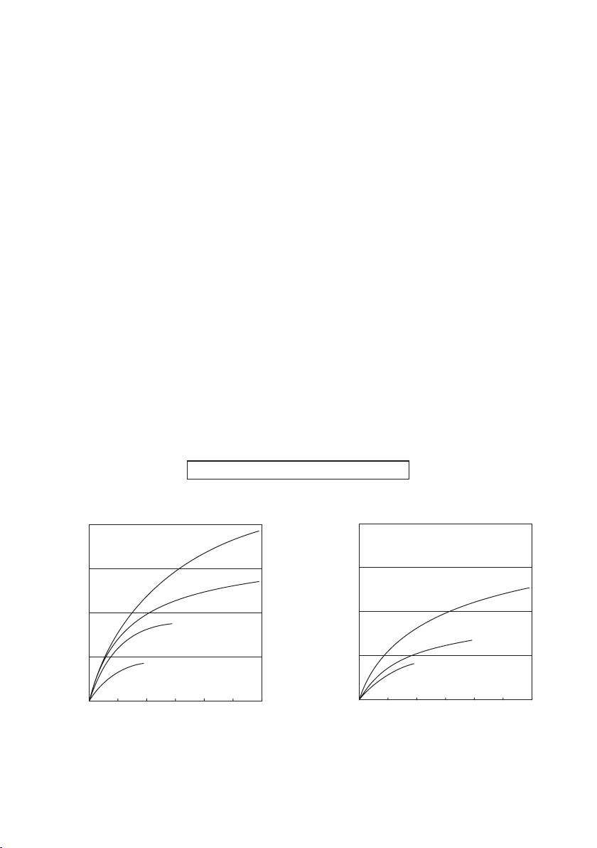
V
. TIGHTENING TORQUE
The power required for tightening a bolt will vary, according to bolt material and size, as well as
the material being bolted. Choose the length of tightening time accordingly.
Reference values are provided below.
(They may vary according to tightening conditions.)
Factors Affecting Tightening Torque
The tightening torque is affected by a wide variety of factors including the followings. After
tightening, always check the torque with a torque wrench.
1) Voltage
When the battery pack becomes nearly discharged, the voltage decreases and the tighten-
ing torque drops.
Bolt Tightening Conditions
-
12
-
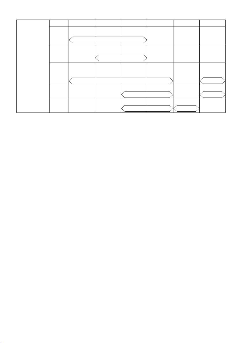
196.0
(2000)
M16
147.0
(1500)
M14
98.0
(1000)
M12
49.0
(500)
M10
0.0 0.5 1.0 1.5 2.0 2.5 3.0
N·m
M10×35 mm M12, M14, M16×45 mm
(kgf-cm)
Standard bolt
Tightening torque
Tightening time (Sec.)
196.0
(2000)
147.0
(1500)
M12
98.0
(1000)
M10
49.0
(500)
M8
0.0 0.5 1.0 1.5 2.0 2.5 3.0
N·m
M8, M10×35 mm M12×45 mm
(kgf-cm)
High tensile bolt
Tightening torque
Tightening time (Sec.)
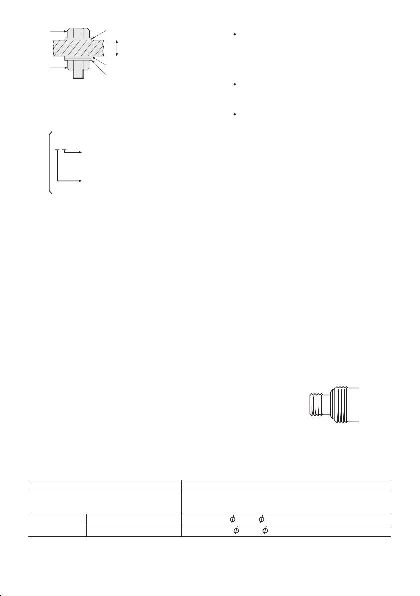
Washer
Bolt
Steel plate
thickness10 mm (3/8")
Washer
Nut
Spring washer
Tightening conditions
• The following bolts are used.
Standard bolts: Strength type 4.8
High tensile type 12.9
-
13
-
4.8
Explanation of the strength type
Bolt yield point
(80% of tensile strength)
2
32 kgf/mm
(45000psi)
Bolt tensile strength
2
40 kgf/mm
(56000psi)
4) Tightening conditions
Tightening torque will vary, even with the
same bolt, according to grade, length, and
torque coefficient (the fixed coefficient indi-
cated by the manufacturer upon produc-
tion).
Tightening torque will vary, even with the
same bolting material (e.g. steel), accord-
ing to the surface finish.
Torque is greatly reduced when the bolt
and nut start turning together.
5) Socket play
Torque is lowered as the six-sided configu-
ration of the socket of the wrong size is
used to tighten a bolt.
6) Switch (Variable speed control trigger)
Torque is lowered if the unit is used with
the switch not fully depressed.
2) Tightening time
7) Effect of connecting adaptor
Longer tightening time results in increased
The tightening torque will be lowered
tightening torque. Excessive tightening, how-
through the use of a universal joint or a
ever, adds no value and reduces the life of
connecting adaptor.
the tool.
3) Different bolt diameters
The size of the bolt diameter affects the tight-
ening torque.
Generally, as the bolt diameter increases,
tightening torque rises.
VI
. ACCESSORIES
Use only bits suitable for size of drill’s chuck.
Use Panasonic original Optional Quick change chuck
(EY9HX110E) for maximum performance.
(EY9HX110E)
VII
. APPENDIX
MAXIMUM RECOMMENDED CAPACITIES
Model
EY7541
Standard bolt: M6 – M16
Bolt fastening
High tensile bolt
: M6 – M12
Wood screw
3.5 – 9.5 mm (1/8" – 3/8")
Screw driving
Self-drilling screw
3.5 – 6 mm (1/8" – 1/4")

VIII
. SPECIFICATIONS
MAIN UNIT
Model EY7541
Motor 14.4 V DC
-1
soft mode 0 – 1000 min
(rpm)
-1
No load speed
medium mode 0 – 1400 min
(rpm)
-1
hard mode 0 – 2300 min
(rpm)
Maximum torque 185 N·m (1890 kgf-cm, 1640 in-lbs)
-1
soft mode 0 – 2000 min
(ipm)
-1
Impact per minute
medium mode 0 – 2800 min
(ipm)
-1
hard mode 0 – 3000 min
(ipm)
Overall length 167 mm (6-9/16")
Weight (with battery pack: EY9L40) 1.5 kg (3.3 lbs)
Weight (with battery pack: EY9L41) 1.55 kg (3.4 lbs)
Noise
See the included sheet.
Vibration
BATTERY PACK
Model EY9L40 EY9L41
Storage battery Li-ion Battery
Battery voltage 14.4 V DC (3.6 V × 4 cells)
Capacity 3 Ah 3,3 Ah
BATTERY CHARGER
Model EY0L80
Rating See the rating plate on the bottom of the charger.
Weight 0.95 kg (2.1 lbs)
[Li-ion battery pack]
14.4 V 21.6 V 28.8 V
EY9L40 EY9L60 EY9L80
Charging time
3 Ah
Usable: 35 min. Usable: 45 min. Usable: 55 min.
Full: 50 min. Full: 60 min. Full: 70 min.
14.4 V
EY9L41
Charging time
3,3 Ah
Usable: 45 min.
Full: 60 min.
-
14
-
[Ni-Cd/Ni-MH battery pack]
7.2 V
9.6 V 12 V 15.6 V 18 V 24 V
EY9065
EY9080
EY9001
1.2 Ah
EY9066
EY9086
20 min.
EY9180
EY9101
1.7 Ah
EY9182
EY9103
25 min.
EY9106
Charging time
EY9116
EY9168 EY9188
EY9107
EY9136
2 Ah
EY9117
EY9108
30 min.
60 min.
EY9200 EY9230 EY9210
3 Ah
45 min. 90 min.
EY9201 EY9231 EY9251
3.5 Ah
55 min. 65 min.
NOTE: This chart may include models that are not available in your area.
Please refer to the latest general catalogue
.
NOTE: For the dealer name and address, please see the included warranty card.
-
15
-
IMPORTANT:
ONLY FOR U. K.
The wires in this mains lead are
coloured in accordance with the follow-
ing code:
IX
. ELECTRICAL PLUG
Blue: Neutral
INFORMATION
Brown: Live
As the colours of the wire in the mains lead
FOR YOUR SAFETY PLEASE READ
of this appliance may not correspond with
THE FOLLOWING TEXT CAREFULLY
the coloured markings identifying the termi-
This appliance is supplied with a moulded
nals in your plug, proceed as follows.
three pin mains plug for your safety and
The wire which is coloured BLUE must be
convenience.
connected to the terminal in the plug which
A5ampfuseisttedinthisplug.
is marked with the letter N or coloured
Should the fuse need to be replaced please
BLACK.
ensure that the replacement fuse has a rat-
The wire which is coloured BROWN must be
ing of 5 amp and that it is approved by ASTA
connected to the terminal in the plug which is
or BSI to BS1362.
marked with the letter L or coloured RED.
Check for the ASTA mark or the BSI
Under no circumstances should either of
mark on the body of the fuse.
these wires be connected to the earth ter-
If the plug contains a removable fuse cover
minal of the three pin plug, marked with the
youmustensurethatitisrettedwhenthe
letter E or the Earth Symbol .
fuse is replaced.
If you lose the fuse cover the plug must
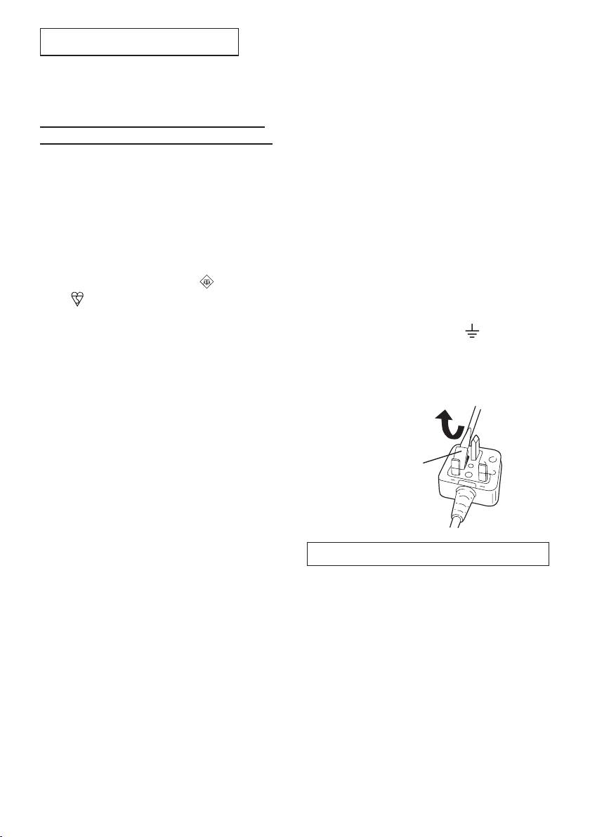
How to replace the fuse: Open the fuse
not be used until a replacement cover is
compartment with a screwdriver and replace
obtained.
the fuse and fuse cover if it is removable.
A replacement fuse cover can be purchased
from your local Panasonic Dealer.
IF THE FITTED MOULDED PLUG IS UN-
SUITABLE FOR THE SOCKET OUTLET IN
Fuse Cover
YOUR HOME THEN THE FUSE SHOULD
BE REMOVED AND THE PLUG CUT OFF
AND DISPOSED OF SAFELY.
THERE IS A DANGER OF SEVERE
ELECTRICAL SHOCK IF THE CUT OFF
PLUG IS INSERTED INTO ANY 13 AMP
This apparatus was produced to BS800.
SOCKET.
Ifanewplugistobettedpleaseobserve
the wiring code as shown below.
If in any doubt please consult a qualied
electrician.
-
16
-

-
17
-
