Panasonic TYST20K: Assembly Procedure
Assembly Procedure: Panasonic TYST20K
11
Assembly Procedure
(Cont’d)
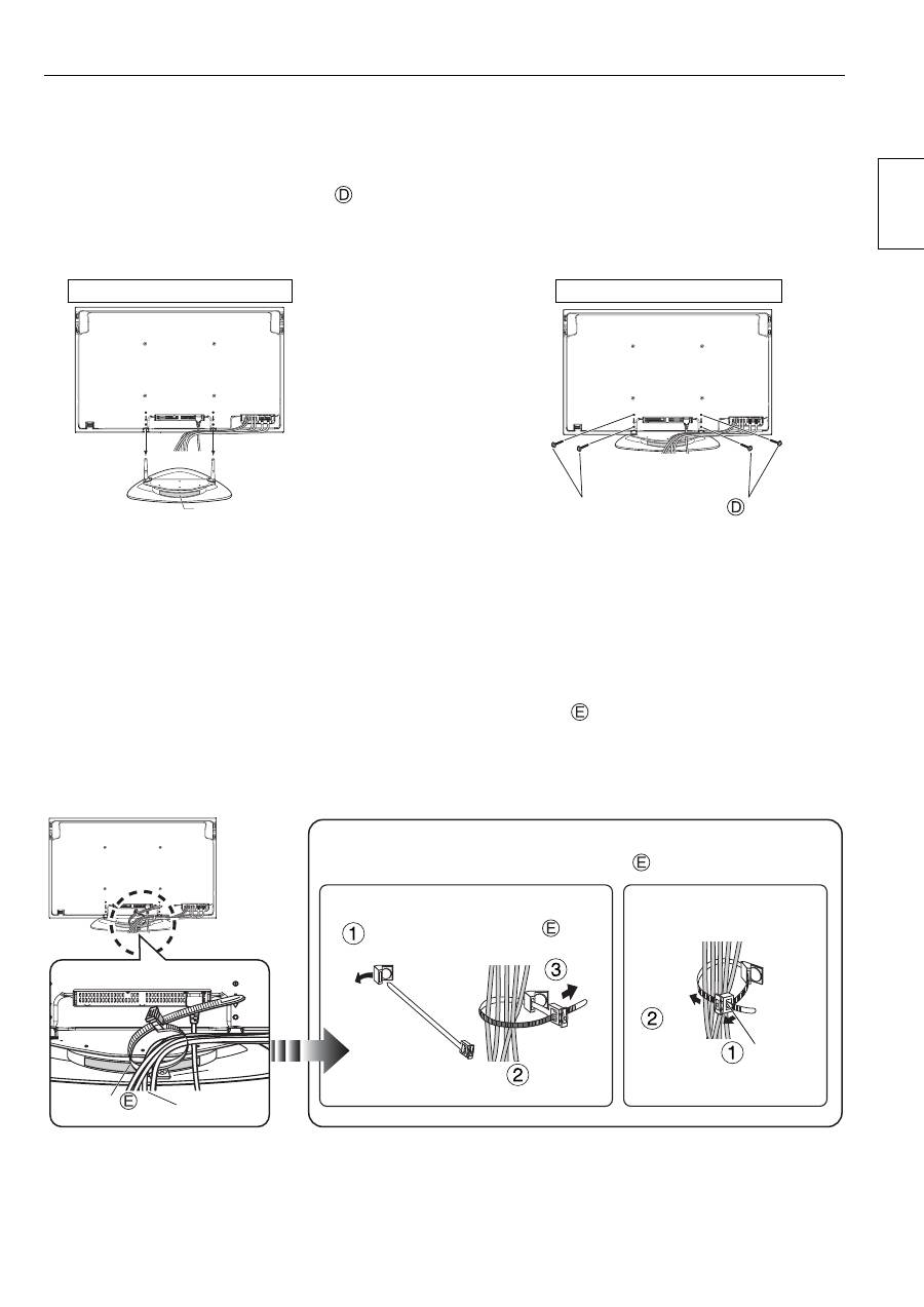
2. Install the Plasma Display
Place the assembled pedestal with the rear side (side with the model nameplate attached) facing towards
yourself, align the plasma display with the stand poles, insert the stand poles into the plasma display, and insert
and tighten the unit installation screws
(4 screws).
(Tightening torque: 1.5 to 1.8 N•m)
3. Connecting Additional Equipment and the Power Cord
●
For details on wiring connections, see the instruction manual of the plasma display.
●
Connect the necessary wiring for the additional equipment, pass a clamper
(1 clamper) through the clip on the
rear of the stand base, and bunch together all of the cords and cables as shown in the diagram.
●
Do not bunch the power cord together with other cords and cables.
Rear View
While ensuring there is sufficient slack in the cord to minimize stress,
firmly bind cables with the supplied clamper
.
Binding the Cables
Pass the tip of the clamper
through the clip
Pull
Bundle
all cables
tidily
Unbinding the Cables
Pull
Pull the lock
section of the
clamper
Clamper
Cables
Clip
Unit installation screw
Model Nameplate
With the side that has the model nameplate
attached facing you, insert the stand poles as
far as possible into the plasma display.
Rear of Plasma Display
Rear of Plasma Display
English
12
Assembly Procedure
(Cont’d)
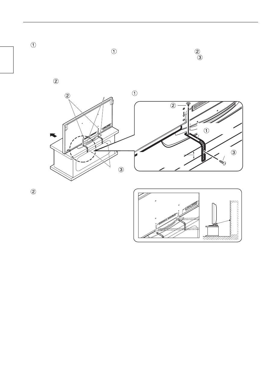
4. Plasma Display Overturn-Prevention
●
Anchor the plasma display to both the base and the wall surface.
Anchoring to the base
Attach the overturn-prevention belts
(2 belts) to the pedestal using screws
(2 screws) through the
screw holes at both sides of the rear of the pedestal, and use the wood screws
(2 screws) to anchor to the
base.
When attaching to the base, insert the wood screws into the prepared holes.
If there are no prepared holes, drill new holes to the center of the base board width.
(Screw
tightening torque: 1.2 to 1.5 N•m)
Anchoring to the wall
Pass sturdy string, wire, or other such
commercially available item through the
holes at both sides of the rear of the
pedestal, and anchor the string etc. to a
secure wall or pillar.
Screw
Screw
Overturn-prevention belt
Overturn-prevention
belt
Front face
Wood screw
Wood
screw
Locate the wood screw at
the center of the material
width.
[For safety reasons, always use the overturn/fall prevention accessories]
The equipment may overturn in the event of an earthquake etc. Therefore, always use the overturn/fall
prevention accessories.
※
The details in this section indicate how to reduce any damage or injury caused by this equipment
overturning or falling due to an earthquake. However, there is no guarantee that the overturn/fall
prevention accessories will be effective in all earthquake situations.
Surface of wall
English
Оглавление
- 安全上のご注意
- 構成部品
- 組み立て手順
- Safety precautions
- Components
- Assembly Procedure
- Sicherheitsmaßnahmen
- Bauteile
- Montage
- Veiligheidsmaatregelen
- Onderdelen
- Montageprocedure
- Precauzioni di sicurezza
- Parti
- Procedura di montaggio
- Précautions de sécurité
- Pièces
- Procédure de montage
- Precauciones para su seguridad
- Componentes
- Procedimiento de montaje
- Säkerhetsföreskrifter
- Beståndsdelar
- Monteringsprocedur
- Sikkerhedsforholdsregler
- Komponenter
- Monteringsprocedure
- Меры предосторожности
- Компоненты
- Процедура сборки
- Сақтық шаралары
- Компоненттер
- Жинақтау процедурасы
- Запобіжні заходи
- Деталі
- Процедура збирання
- 安全警告
- 配件說明
- 裝配程序
