Panasonic TYWK42PR4W: Fitting procedure
Fitting procedure: Panasonic TYWK42PR4W
4
English
Fitting procedure
[ Never use any other method
than specified to install.]
1. Confirm the strength of the proposed fitting location.
(1) The weight of the wall-hanging bracket is approximately 10 kg (22.0 lbs). For the weight of
the plasma TV attached to the wall-hanging bracket, please see manual for the plasma TV.
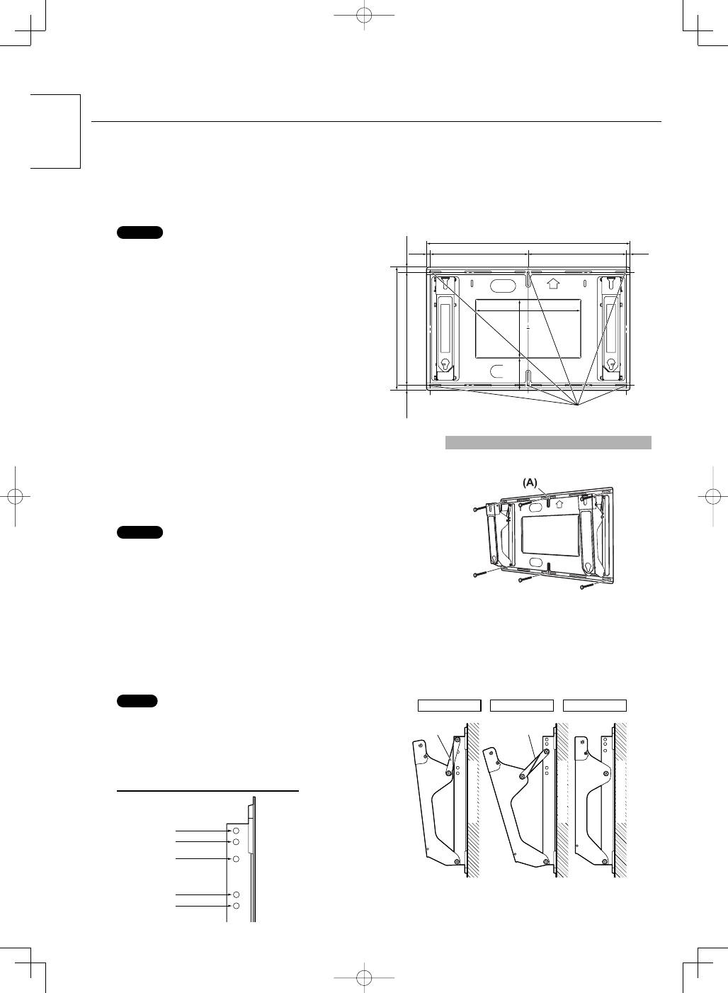
(2) Check the wall strength at the 6 attachment locations by referring to the dimension drawing
of the wall-hanging bracket (given at right), and provide adequate reinforcement if strength
is not sufficient.
Notes
• There are 16 holes in the wall-hanging bracket.
If the wall material is wood, and adequate attachment
strength cannot be ensured by fastening at the 6 points at
right, use as many spare holes as necessary. However,
exercise care because some wall materials may crack if
screws are located too close together.
• For detailed dimensions for attaching the plasma TV, refer to
the separate External Dimension Drawing (page 46-50).
• Do not attach or place anything other than the plasma TV on
the bracket.
416 (16.4)
810 (31.9)
230 (9.1)
490 (19.3) 450 (17.7)
20 (0.8)
20 (0.8)
390 (15.4)
390 (15.4)
15
(0.6)
15
(0.6)
130 (5.1)
Unit: mm (inches)
* Be sure to fit screws and tighten securely.
Wall attachment
holes (at 6 points)
2. Fit wall-hanging bracket to wall.
(1) Fit so that the arrow marks on the wall-hanging bracket point upward.
(2) Fasten the screw at the top center hole (A) first.
(3) Using a level, correct any bracket inclination, and then fasten screws at the
remaining 5 locations.
Notes
• If the wall consists of a material such as concrete, and bolts or nuts must be
embedded beforehand, determine the hole positions using the actual wall-hanging
bracket, or calculate hole positions based on the dimension drawing and then embed
bolts or nuts with a nominal diameter of 6 mm. When embedding bolts, locate so that
the bolts protrude from the wall by 10 to 15 mm (25/64 to 19/32 inches).
• Use commercially available screws with a nominal diameter of 6 mm that are
suited to the wall material you are fitting the bracket to.
• Always fix firmly more than 6 places with a screw.
3. Angle adjustment of wall-hanging bracket.
The angle of the wall-hanging bracket can be adjusted from “no incline” to “20° incline” in 5 settings at intervals of 5°.
The bracket is set to 5° before shipment from the factory.
To change the angle, move the attachment position of the strap.
Note
• The strap is not required for the ‘no incline’ setting. Store the
strap and the attaching screws in a safe place (as they will be
needed for the inclined settings.)
The bolt should be securely tightened to the torque given
below.
(11 - 13 N•m)
At 5° incline
Strap
Strap
At 15° incline
No incline
W
all surface
W
all surface
W
all surface
Angle adjustment hole positions
5° incline
10° incline
15° incline
20° incline
No incline
TY-WK42PR4W̲TQZH993-3̲4048.indb 4
TY-WK42PR4W̲TQZH993-3̲4048.indb 4
2008/04/07 11:56:36
2008/04/07 11:56:36
5
English
5
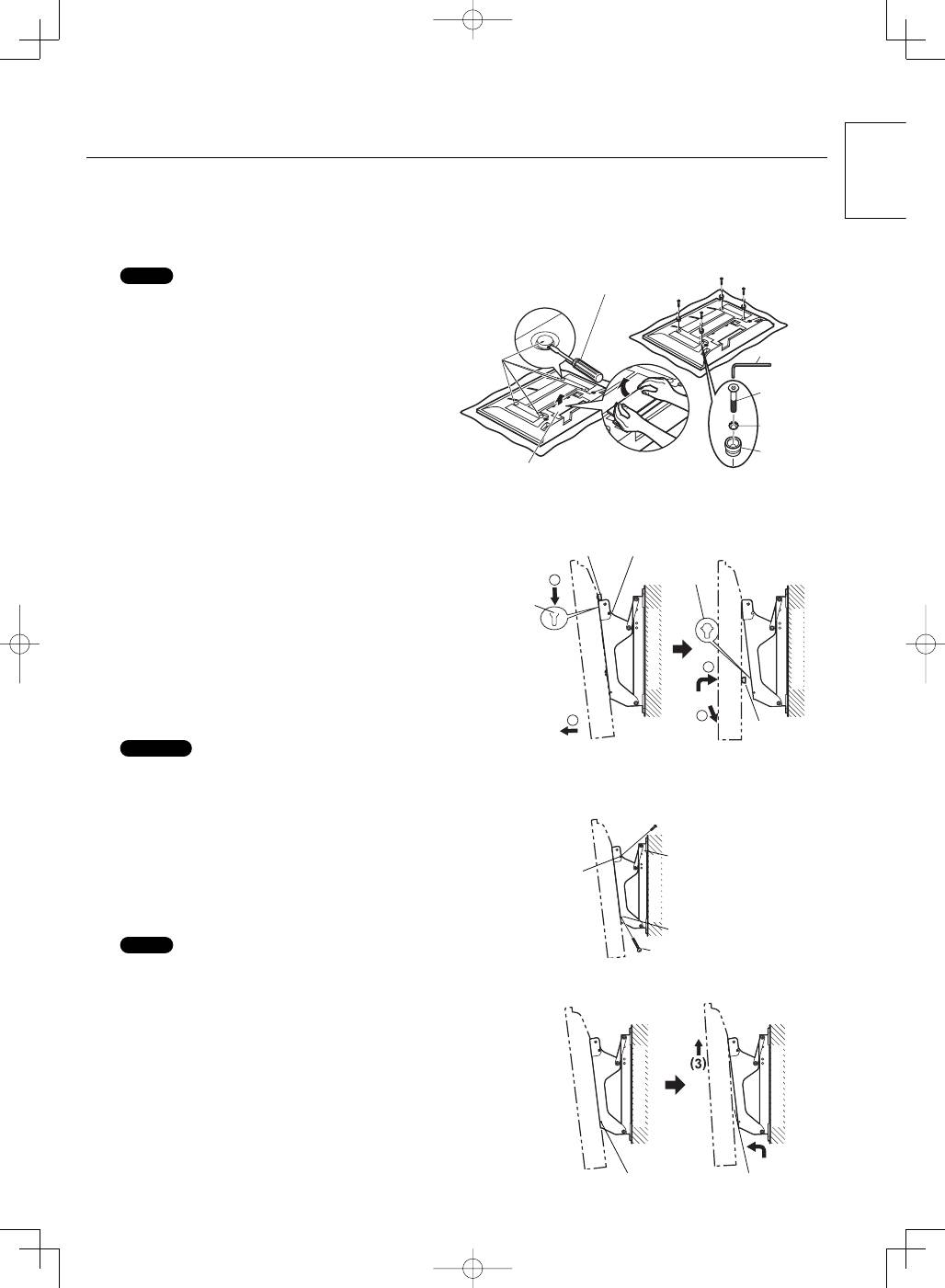
4. Fit the insulation spacers to the plasma TV.
(1) Place the plasma TV unit face down on a blanket or other soft cloth that is clean and free of debris, and follow the
procedure below.
(2) Remove terminal covers (if fitted) from the plasma TV.
(3) Using a flathead screwdriver, remove the four caps from the plasma TV.
Note
• Carefully retain the removed terminal cover and caps in a
safe place. (They will be needed again later should it be
required to use the special-purpose stand or standalone
stand.)
Terminal cover
Caps
Flathead screwdriver
㇜
㇞
or
㇟
㇛
㇚
(4) Using the included Allen wrench
㇜
, fit the included
Allen head countersunk screws
㇞
or
㇟
dished toothed
washers
㇛
and insulation spacers
㇚
(4 sets) into the
holes from where the caps were removed. (See the
diagram at right.)
Refer to the page 46-50 for type selection of allen head
countersunk screws
㇞
,
㇟
.
The bolt should be securely tightened to the torque given
below.
(3 - 4 N•m)
5. Attaching the plasma TV to the wall-
hanging bracket and connecting the
wiring.
2
3
4
5
Top insulation
spacer
㊍
Red screw for open /
close fastening
Top notch
Lower hole
Lower
insulation
spacer
W
all surface
W
all surface
(1) Remove the red screws for open/close fastening (one each on
the left and right)
㊍
.
(2) Hook the insulation spacers on the top of the plasma TV over
the notches on the bracket, and allow the TV to hang from the
bracket.
(3) Pull the plasma TV body forward, as shown in the diagram at
right, and connect the wiring.
(4) After wiring is finished, slightly raise the plasma TV and insert
the insulation spacers at the lower back into the holes at the
base of the wall-hanging bracket.
(5) Lower the plasma TV into place.
Caution
• If the plasma TV is raised too far, there is a risk it may become
unhooked from the top of the bracket.
6. Fastening the plasma TV.
W
all surface
Hole for red
screw for
open / close
fastening
㊍
Red screw for open/
close fastening
Wall-hanging bracket
Fastening screw fitting
position
Plasma TV fastening screw
(1) Fit the included fastening screws in the indicated holes at the
sides of the wall-hanging bracket (left and right).
(2) Securely refit the red screws for open/close fastening (one
each on the left and right)
㊍
in the indicated holes on the
sides of the wall-hanging bracket.
The bolt should be securely tightened to the torque given below.
(1.2 - 1.5 N•m)
Note
• Be sure to fit the fastening screws on the left keep lifting upward.
and right to keep the plasma TV from falling off the wall-hanging
bracket.
7. Removal of plasma TV unit.
(1) Screw for plasma
TV unit fastening
(2) Insulation spacer
W
all surface
W
all surface
(1) Remove the screws for unit fastening (1 each on the left and
right) that are fitted to the wallhanging bracket sides.
(2) While lifting the bottom of the plasma TV unit, pull it towards
yourself.
(3) When the lower insulation spacers are freed, keep lifting
upward.
TY-WK42PR4W̲TQZH993-3̲4048.indb 5
TY-WK42PR4W̲TQZH993-3̲4048.indb 5
2008/04/07 11:56:37
2008/04/07 11:56:37
Оглавление
- Safety precautions
- Components
- Fitting procedure
- Sicherheitsmaßnahmen
- Bauteile
- Befestigung
- Veiligheidsmaatregelen
- Onderdelen
- Montageprocedure
- Precauzioni di sicurezza
- Parti
- Procedura di montaggio
- Précautions de sécurité
- Pièces
- Mode de pose
- Precauciones para su seguridad
- Componentes
- Procedimiento de instalación
- Säkerhetsföreskrifter
- Beståndsdelar
- Monteringsprocedur
- Sikkerhedsforholdsregler
- Komponenter
- Opsætningsprocedure
- Меры предосторожности
- Компоненты
- Процедура монтажа
- Запобіжні заходи
- Деталі
- Монтаж
- ࣋ภܿ᎙ሃჵ
- ெؠ
- Ꭷ؞ᎁ
