Panasonic AK-HRP150: Major operating controls and their functions
Major operating controls and their functions: Panasonic AK-HRP150
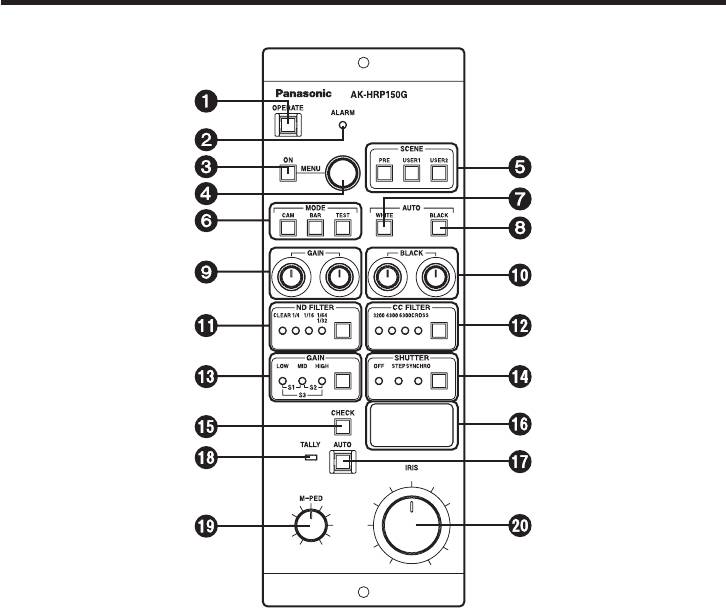
Major operating controls and their functions
Operation panel
OPERATE switch [OPERATE]
This switch allows operations to be performed using the controls on the remote control
panel. Its lamp lights up as soon as the power is turned on.
Lighted: The switch lamp lights up when the power is turned on.
When communication with the camera is enabled, switch selection is
set.
Extinguished: If the power has been turned on and the camera’s power is on, the
operations will be canceled (set to the protected status).
Alarm indicator [ALARM]
This lights up red when the camera’s fan has shut down. Normally, it goes off.
MENU ON/OFF switch [MENU ON]
This is used to display the menus on the main line images.
- 7 (E) -

Major operating controls and their functions
Menu switch [MENU]
ENGLISH
When this switch is rotated, menu items can be selected and data changed.
When it is pressed, items can be verified and data entered.
Scene file switches [SCENE PRE, USER1, USER2]
These switches are used to call the scene file data registered by the camera.
Camera video output selector switches [MODE CAM/BAR/TEST]
These switches are used to select the camera video output. Camera video, color bar
display or test display is selected.
CAM switch lamp lighted: Output of images shot by camera
BAR switch lamp lighted: Color bar output
TEST switch lamp lighted: Test signal output
Auto white balance switch [AUTO WHITE]
This switch is used for automatic white balance adjustments.
Switch lamp lights: When the switch is pressed, the start of the automatic white
balance operation is indicated by the lighting of the switch lamp.
Switch lamp flashes: If the white balance is not adjusted adequately upon completion
of the automatic white balance adjustment, the lamp flashes to
warn the user.
Switch lamp goes off: The lamp goes off when the white balance has been adjusted
satisfactorily.
Auto black balance switch [AUTO BLACK]
This switch is used for automatic black balance adjustments.
Switch lamp lights: When the switch is pressed, the start of the automatic black
balance operation is indicated by the lighting of the switch lamp.
Switch lamp flashes: If the black balance is not adjusted adequately upon completion
of the automatic black balance adjustment, the lamp flashes to
warn the user.
Switch lamp goes off: The lamp goes off when the black balance has been adjusted
satisfactorily.
R/B gain control [GAIN]
This control is used to adjust the red (R) and blue (B) of the white balance. Automatic
white balance operations can be performed while these colors are being adjusted.
R/B pedestal control [BLACK]
This control is used to adjust the red (R) and blue (B) of the pedestal. Automatic black
balance operations can be performed while these colors are being adjusted.
- 8 (E) -
Major operating controls and their functions
ND filter switch [ND FILTER]
This switch is used to select the ND filter setting.
ND_1: CLEAR
ND_2: 1/4
ND_3: 1/16
ND_4: 1/32 or 1/64
The ND filter differs depending on the camera concerned. For details, refer to the camera’s
instruction manual.
CC filter switch [CC FILTER]
This switch is used to select the CC filter selection.
CC_A: 3200K
CC_B: 4300K
CC_C: 6300K
CC_D: Cross screen
This function does not work with AK-HC1500G.
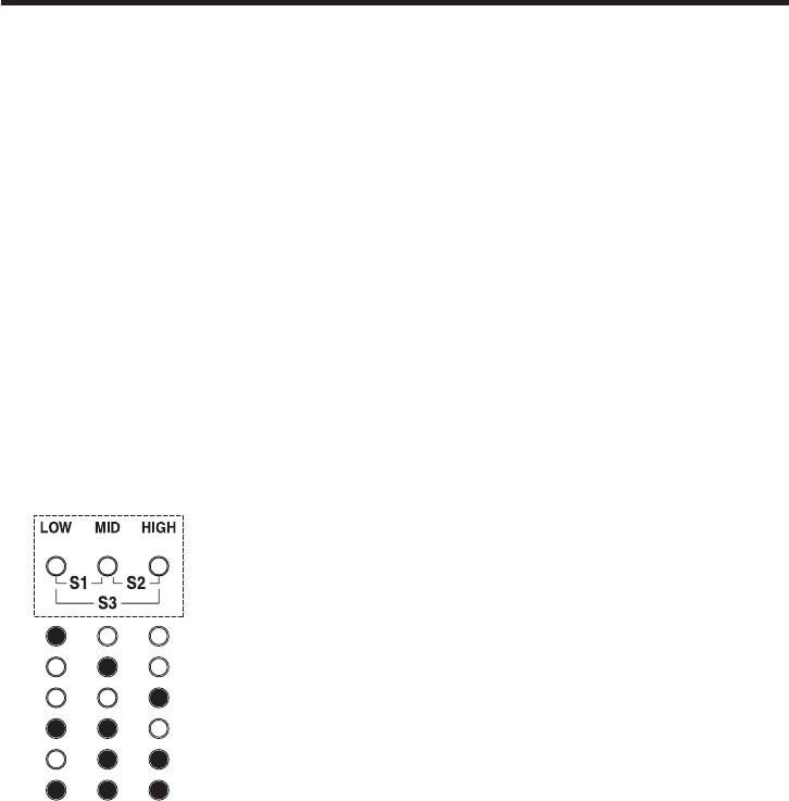
Gain switching status display [GAIN]
This indicates the gain of the video input sensitivity.
LOW gain status
MID gain status
HIGH gain status
Super gain 1 status
Super gain 2 status
Super gain 3 status
Electronic shutter switch [SHUTTER]
This switch is used to set the step shutter or synchro scan shutter set using the camera
menu to ON or OFF. The switch lamp lights when one of the shutters is selected.
- 9 (E) -

Major operating controls and their functions
Iris f-number, master pedestal display selector switch [CHECK]
ENGLISH
This switch is used to toggle between the f-number display and master pedestal display.
Iris f-number, master pedestal indicator
This indicator displays figures for the iris f-number and master pedestal.
Auto iris switch [AUTO]
This switch is used to turn on the auto iris function.
Switch lamp lighted: Auto iris status
Tally indicator [TALLY]
This lights when the tally input (MAKE) is supplied to the tally connector.
Master pedestal control [M-PED]
This control is used to adjust the master pedestal level. When it is turned clockwise, the
master pedestal level increases.
Iris control [IRIS]
This control is used to adjust the lens iris level.
- 10 (E) -
Major operating controls and their functions
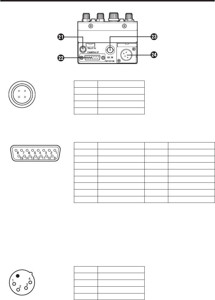
Rear panel
Tally signal input connector [TALLY IN]
Pin No. Signal
1 R TALLY
2 N.C.
3 N.C.
4 R TALLY COM
Camera I/F connector [CAMERA I/F]
Connected to the camera (AK-HC1500G) with the attached multi cable.
Pin No. Signal Pin No. Signal
1 — 9 —
2 — 10 —
3 — 11 G/L GND
4 G/L output 12 DC12 V GND
5 DC12 V output 13 TX_N output
6 GND 14 RX_P input
7 TX_P output 15 RX_N input
8 —
TXD: Data from camera to remote controller.
RXD: Data from remote controller to camera.
Synch signal input connector [G/L IN]
Inputs the sync signal to the camera.
DC12 V input connector [DC12V IN] (XLR4-pin)
Connects the AC adapter. We recommend that the AW-PS505A (sold separately) is
used.
Pin No. Signal
1 GND
2 N.C.
3 N.C.
4 DC12V
- 11 (E) -
Оглавление
- IMPORTANT SAFETY INSTRUCTIONS
- Contents
- Precautions for use
- Major operating controls and their functions
- Multi purpose camera control system configuration
- Appearance
- Specifications
- Inhalt
- Vorsichtsmaßnahmen zum Gebrauch
- Wichtige Bedienungselemente und ihre Funktionen
- Konfiguration des Mehrzweckkamera-Steuersystems
- Aussehen
- Technische Daten
- Table des matières
- Précautions d’utilisation
- Principaux organes de commande et leurs fonctions
- Configuration du système de commande de la caméra multi-usages
- Aspect extérieur
- Fiche technique
- Sommario
- Precauzioni per l’uso
- Comandi principali e loro funzioni
- Configurazione del sistema di controllo della videocamera multifunzione
- Aspetto
- Dati tecnici
- Índice
- Precauciones para la utilización
- Controles de las operaciones principales y sus funciones
- Configuración del sistema de control para cámara de múltiples propósitos
- Apariencia
- Especificaciones
- Содержание
- Меры предосторожности во время использования
- Основные устройства управления и их функции
- Конфигурация системы управления многоцелевой камерой
- Внешний вид
- Технические характеристики
- 目 录
- 产品介绍
- 使用注意事项
- 主要操作控制器及其功能
- 多功能摄像机控制系统配置
- 外部尺寸图
- 规 格
- 安全上のご注意
