Panasonic EYFLA1: IV
IV: Panasonic EYFLA1
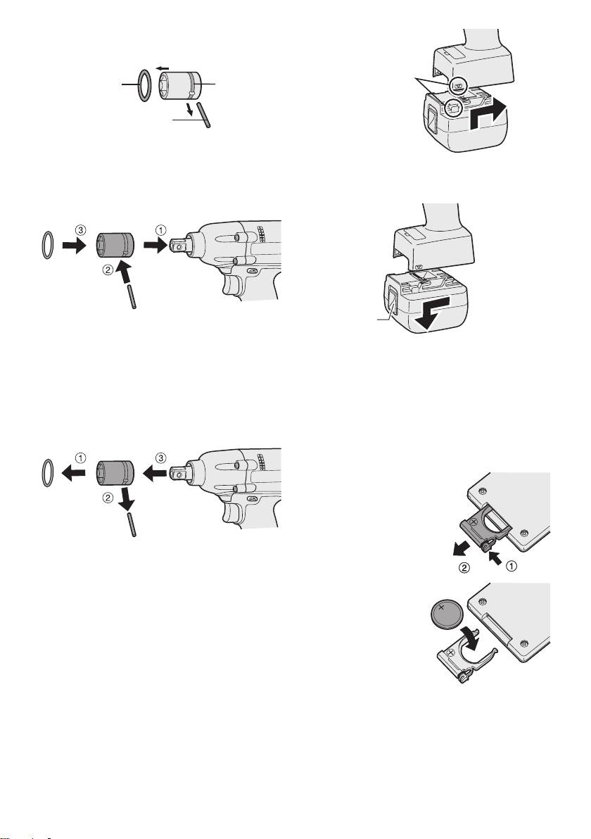
Attaching Socket
• Remove the socket’s rubber ring and pin.
Alignment
rubber
ring
groove
marks
pin
1 Attach the socket to the tool.
2 Insert
the pin. (Taking care to align the pin
2. To remove the battery pack:
holes on the socket and tool.)
Push up on the button from the front to re-
3 A
ttach the rubber ring by sliding it into place
lease the battery pack.
over the groove.
Button
NOTE:
Be sure to attach the rubber ring to prevent
the pin from falling out.
IV
. OPERATION
Removing Socket
Before Using the Remote
1 Remove the rubber ring.
2 Remove the pin.
Control (Available as an
3 R
emove the socket from the tool.
optional accessory)
Insert the battery
1. Pull out the battery holder.
1 P
ush in on the fas-
tener as indicated by
the arrow.
2 Pull out the holder
.
NOTE:
Keep the temperature of the tool above
the
freezing point (0°C/32°F) when attach-
2. Insert the battery and
ing sockets to or detaching them from
push the holder
the square drive on the tool. Do not use
back in.
excessive
force when attaching or detach-
ing sockets.
Attaching or Removing Bat-
tery Pack
NOTE:
1. To connect the battery pack:
•
If the tool does not respond to the wire-
Line up the alignment marks and attach
less remote control even when the remote
the battery pack.
control is operated close to the tool, the
battery (CR2025) is dead. Replace it with
•
Slide the battery pack until it locks into
a fresh battery.
position.
•
The included battery is provided for sam-
ple use and may not last as long as com-
mercially available batteries.
-
7
-
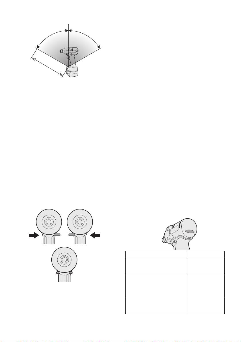
Wireless remote control range
-
8
-
Vertically
A
p
6
0
°
p
r
o
.
x
x
.
o
6
r
0
p
°
p
A
Approx. 50 cm
The remote control should be operated within
approximately 50 cm and approximately 60°
vertically and horizontally of the perpendicular
relative to the infrared receiver on the tool.
•
Under the following circumstances, you may
not be able to operate the tool, even within
this range.
•
If there is an object between the remote
control’s transmitter and the tool’s receiver.
•
Use outdoors or in other environments
where the remote control receiver is
exposed to a strong light source, or when
the remote control transmitter or receiver is
dirty may cause the tool to fail to respond,
even when the remote control is used within
the operating range.
[Main Body]
Switch and Forward/Reverse
Lever Operation
Forward Reverse
Switch lock
Forward Rotation Switch
Operation
1. Push the lever for forward rotation.
2. Depress the trigger switch slightly to start
the tool slowly.
3.
The speed increases with the amount of
depression of the trigger for efficient tight-
ening of screws. The brake operates and
the bit stops immediately when the trigger
is released.
4.
After use, set the lever to its center posi-
tion (switch lock).
Reverse Rotation Switch
Operation
1.
Push the lever for reverse rotation. Check
the
direction of rotation before use.
2.
Depress the trigger switch slightly to start the
tool slowly.
3. After use, set the lever to its center posi-
tion (switch lock).
CAUTION:
•
To eliminate excessive temperature
increase of the tool surface, do not
operate the tool continuously using two
or more battery packs. Tool needs cool
off time before switching to another
pack.
Tightening confirmation lamp
• The tightening confirmation lamp can be
used to check whether the torque control
function was activated.
Tool status Lamp display
Tightening complete
Green
(with torque control
(For approx. 2
function operation)
seconds)
•
Tightening not complete
Red
• Tightening complete
(For approx. 2
with retightening within 1
seconds)
CAUTION:
second
To prevent damage, do not operate
The automatic stop
Red
Forward/Reverse lever until the bit comes
function has been
(For approx. 5
to a complete stop.
activated.
minutes)
CAUTION:
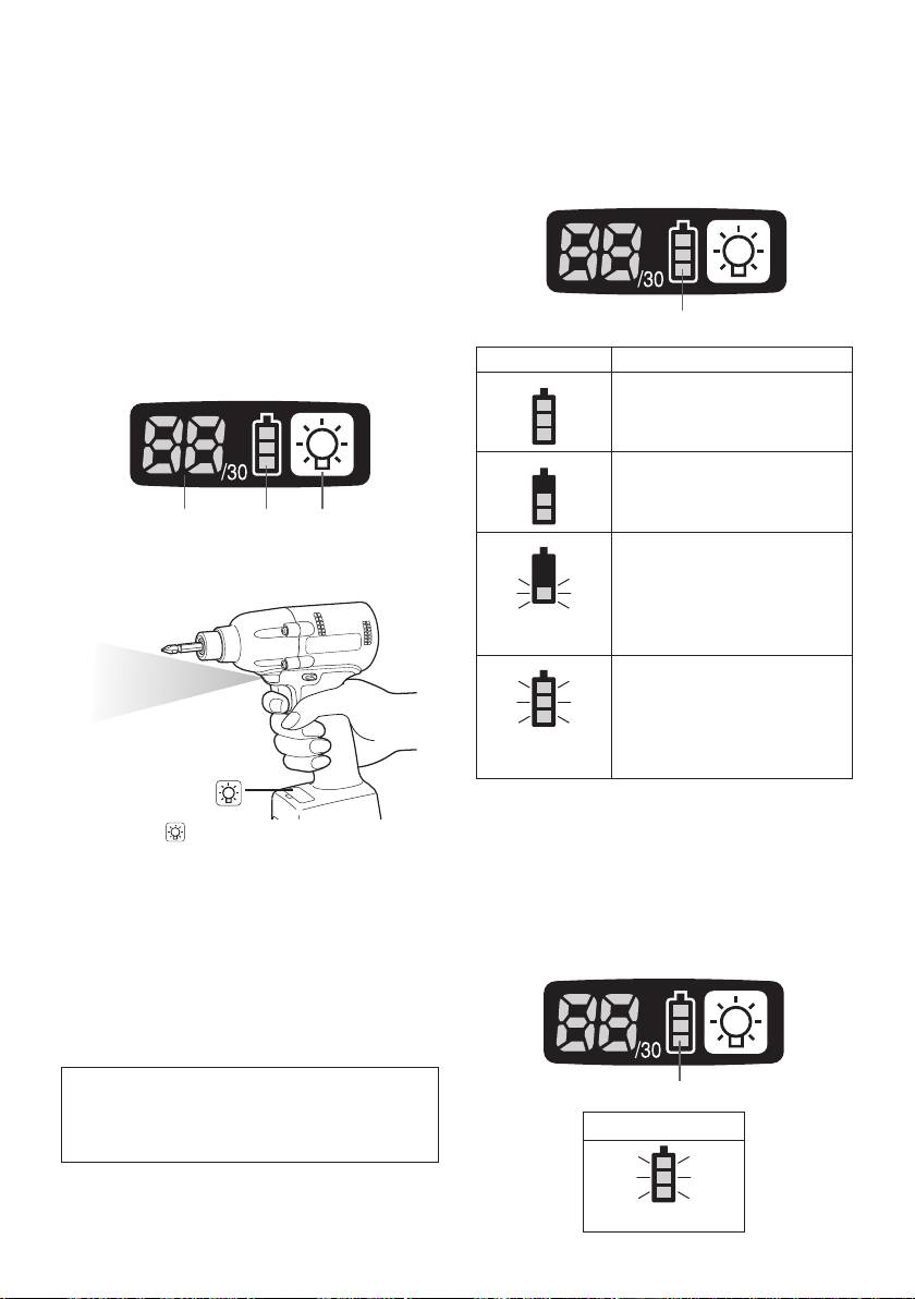
(2) The battery indication lamp
• When the tool stops automatically after
• Use the battery indication lamp to check
the switch is released during impact-
how much power is left in the battery.
mode tightening and then reengaged
within 1 second, the red lamp will light up
•
Battery life varies slightly with ambient tem-
to indicate the risk of excessive torque
perature and battery characteristics. The
application as a result of retightening.
lamp is designed to provide a rough indica-
tion of remaining battery life.
NOTE
•
The tightening confirmation lamp will not
turn on under the following conditions:
•
When the torque clutch is set to “F”
• During reverse rotation operation
• The lamp turns off when the tool is in
Battery indication lamp
operation.
Indicator Battery status
Control Panel
Fully charged
Approx. 40% or less
remaining
(1) (2) (3)
Flashing
(1) LED light
Approx. 20% or less
remaining (indicates need
to recharge battery)
The battery pack will need
Flashing
to be charged soon.
No charge
The battery pack needs to
be charged.
(The tool’s automatic
power-off function will
Flashing
activate at this stage.)
Automatic power-off function
Pressing the button toggles the LED light on
• The automatic power-off function is designed
and off.
to prevent a loss of tightening torque due
The light illuminates with very low current, and
to reduced battery voltage. Once it has
it does not adversely affect the performance
of
been activated, the tool will not operate until
the
tool during use or its battery capacity.
the battery pack has been charged (or re-
CAUTION:
placed with a fresh unit), even if the trigger is
•
The built-in LED light is designed to illu-
depressed.
minate the small work area temporarily.
•
Do not use it as a substitute for a regu-
lar
flashlight, since it does not have
enough brightness
.
Caution : DO NOT STARE INTO BEAM.
Battery indication lamp
Use of controls or adjustments or performance
of procedures other than those specied herein
Indicator
may result in hazardous radiation exposure.
Flashing
-
9
-
NOTE:
2
) Other
• All 3 bars on the battery indication lamp
• Bit and socket condition: Material,
will flash when the automatic power-off
amount of play, etc.
function is activated.
•
Use of a universal joint or socket
•
When the battery indication lamp begins
adapter
flashing, the battery pack should be
•
User: Manner in which the tool is
charged (or replaced with a fresh unit)
applied to the bolt, strength with which
immediately.
the tool is held, manner in which the
•
Be sure to fully charge the battery pack
tool’s switch is engaged
in question after activation of the auto-
•
Condition of object being tightened: Ma-
matic power-off function. Failure to do
terial, seating surface finish
so may prevent the automatic power-off
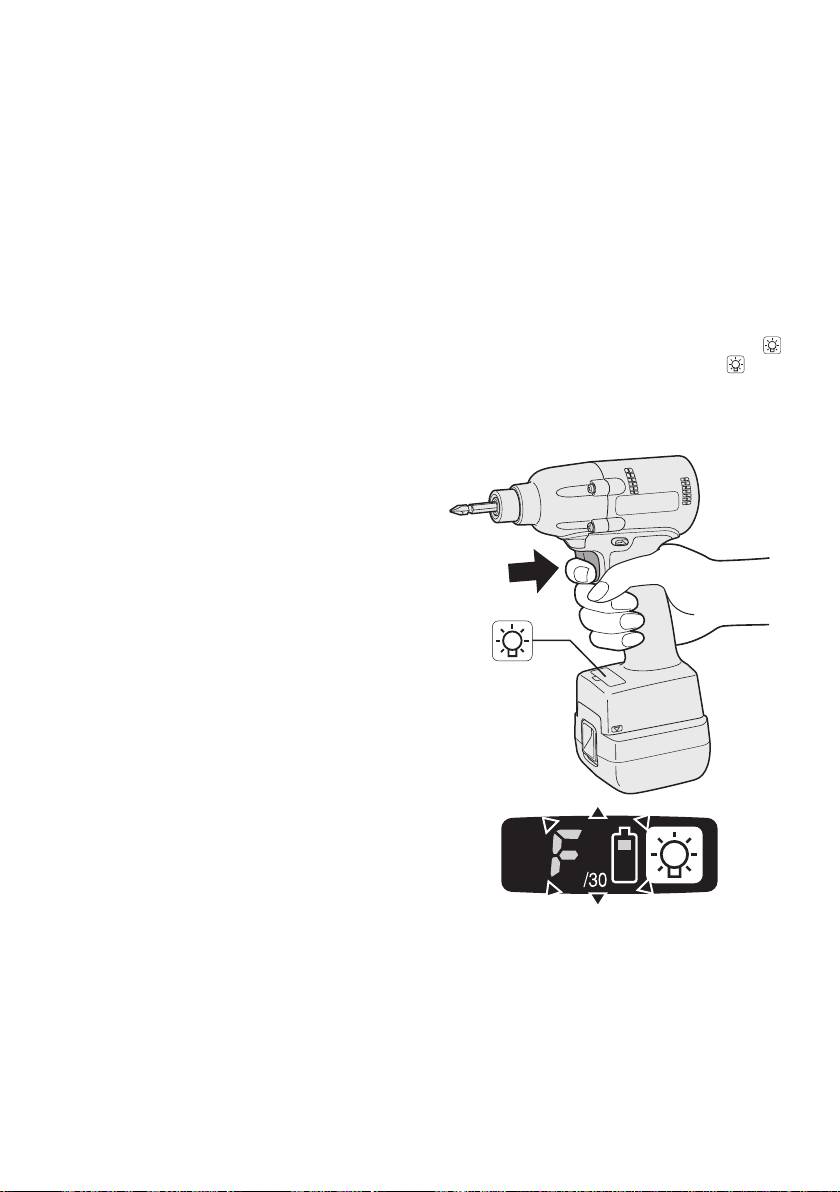
Setting the tool to configuration mode
function from being properly deactivated.
1.
Turn off the control panel.
(3) The torque control function
• If the control panel is on, remove and
then reinsert the battery pack.
• The torque control function calculates the
2.
Engage the switch while pushing the
load from the motor’s rotational angle during
button and then release both the
but-
the hammer impact and determines that the
ton and the switch.
bolt has been properly seated when a pre-
•
After all the LED lamps have turned off,
set load value is exceeded. Driving is then
the control panel will flash and change
automatically stopped after a preset number
to configuration mode.
of impacts have been delivered to the bolt.
CAUTION:
•
Always check the tool’s tightening torque
before use. Improper tool operation may
result in excessive or inadequate tight-
ening.
CAUTION:
•
Always operate the tool with the switch
fully engaged. The torque control func-
tion will not operate when the switch is
not sufficiently engaged, preventing the
tool from stopping automatically.
•
In work where a heavy load comes to
bear during tightening, the load may be
interpreted as the seating of the bolt,
preventing the bolt from being com-
pletely tightened.
•
Repeated tightening of the same bolt
may break the bolt or deform the mate-
rial into which the bolt is being driven as
a result of excessive tightening.
•
The tightening torque value and preci-
sion vary with factors such as the mate-
rial into which the bolt is being driven
and the condition of the socket being
NOTE:
used. Adjust the torque as necessary
• Tools ship from the factory set to “F”
for the work being performed. Bolt tight-
mode (torque control function off).
ening torque varies due to the factors
•
The control panel will turn off if the tool
described below.
is not operated for a period of 5 min-
1) Bolt
utes.
•
Bolt diameter: Tightening torque gener-
ally increases with bolt diameter.
•
Torque coefficient (indicated by the bolt
manufacturer), grade, length, etc.
-
10
-
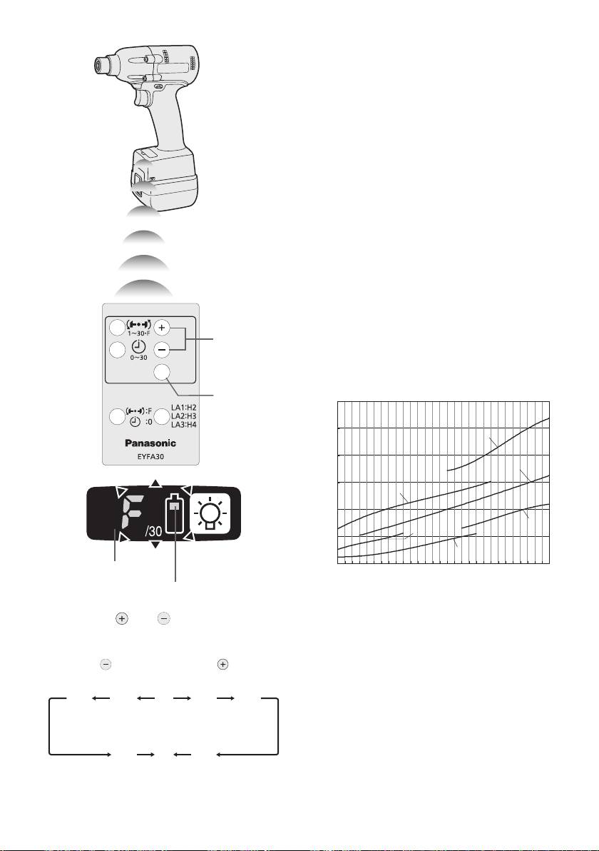
Configuring the torque clutch setting
(1)
(2)
Display
Battery indication lamp
1. Press the and buttons to select the
clutch setting that is appropriate for the
work being performed.
-
11
-
1F30 229
3…28
•
You can select from 30 torque clutch
settings (1 to 30).
•
Use figures from the Tightening Torque
Chart to guide your selection of torque
clutch setting. (See the following tighten-
ing torque chart)
2.
Press the OK button to accept the select-
ed torque clutch setting.
•
The control panel will stop flashing and
light up.
CAUTION:
•
You must press the OK button in order
for the selected setting to take effect.
•
Be sure to verify the new value after
changing the setting. (See page 12.)
Tightening Torque Chart (for Reference
Use)
The values illustrated on this chart were mea-
sured under the conditions described below
and are provided for reference purposes.
Actual tightening torque varies with ambient
conditions (the particular bolt being tightened,
hardware being used, method of holding the
bolt in place, etc.).
As the button
As the button
is pressed
is pressed
• “F” indicates that the torque control func-
tion is off.
N • m
60
50
EYFLA3 (M10)
40
EYFLA2 (M8)
30
EYFLA3 (M8)
20
EYFLA1 (M8)
EYFLA2 (M6)
10
EYFLA1 (M6)
0
1 2 3 4 5 6 7 8 9 101112131415161718192021222324252627282930
Measurement conditions
• Temperature: Room temperature (20°C/68°F)
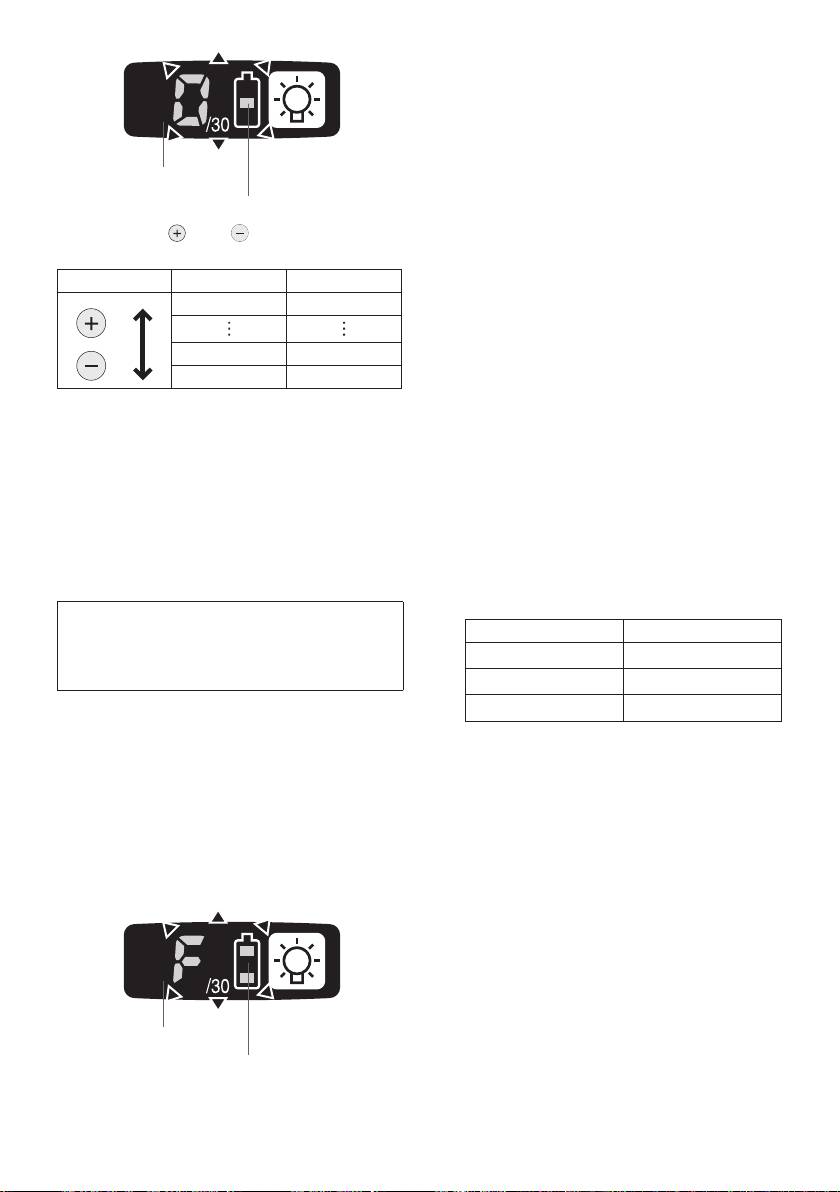
Using the Interval Set
•
The interval set operates to prevent the tool
from operating after it automatically stops as
a result of the torque control function, even if
the switch is engaged.
1.
Set the tool to configuration mode.
(See page 10.)
2. Press the interval set button.
• The control panel will begin flashing.
Display: The number 0 ashes on and off.
Battery indication lamp: The middle bar
of the battery ashes on and off.
•
The control panel will stop flashing and
light up.
Checking Tool Settings
•
This section describes how to have the tool
display current settings for approximately 3
seconds when the tool is stopped.
Display
•
You cannot check tool settings when the
control panel is turned off. First, engage
Battery indication lamp
the switch briefly to reactivate the display.
3. Press the and buttons to set the
Checking the torque clutch setting
desired time.
1.
Press the torque set button.
Buttons Display Seconds
• Control panel display
30 3
Display: The torque set lights up.
Battery indication lamp: The upper bar of
the battery ashes on and off.
1 0.1
0 Off
Checking the interval
1.
Press the interval set button.
4.
Press the OK button to accept the selected
• Control panel display
setting.
Display: The interval set lights up.
•
The control panel will stop flashing and
Battery indication lamp: The middle bar
light up, and the torque clutch setting
of the battery ashes on and off.
will be displayed.
Checking tool circuits
CAUTION:
1.
Press the torque set button.
•
Be sure to verify the new value after
• Control panel display
changing the setting.
Display: The torque set display lights up.
Battery indication lamp: The middle and
Initializing All Settings
lower bars of the battery ash on and off.
Factory settings
Display Tool circuit
• Torque clutch setting: “F” (torque con-
trol function off)
H2 EYFLA1
•
Interval setting: 0 (off)
H3 EYFLA
2
• This section explains how to revert all tool
H4 EYFLA3
settings to their default values at the time of
shipment from the factory.
NOTE:
•
The error display will be turned off.
• If you engage the switch while a setting
is being displayed, the control panel will
1. Set the tool to configuration mode.
revert to the torque clutch setting dis-
(See page 10.)
play.
2. Press the format button.
• The control panel will begin flashing.
CAUTION:
Display: The letter “F” ashes on and off.
•
The torque set display is not intended
Battery indication lamp: The upper and
to be used to identify the type of drive
lower bars of the battery ash on and off.
component parts (hammer, etc.) used
in a particular tool.
Display
Battery indication lamp
3. Press the OK button to accept the select-
ed setting.
-
12
-
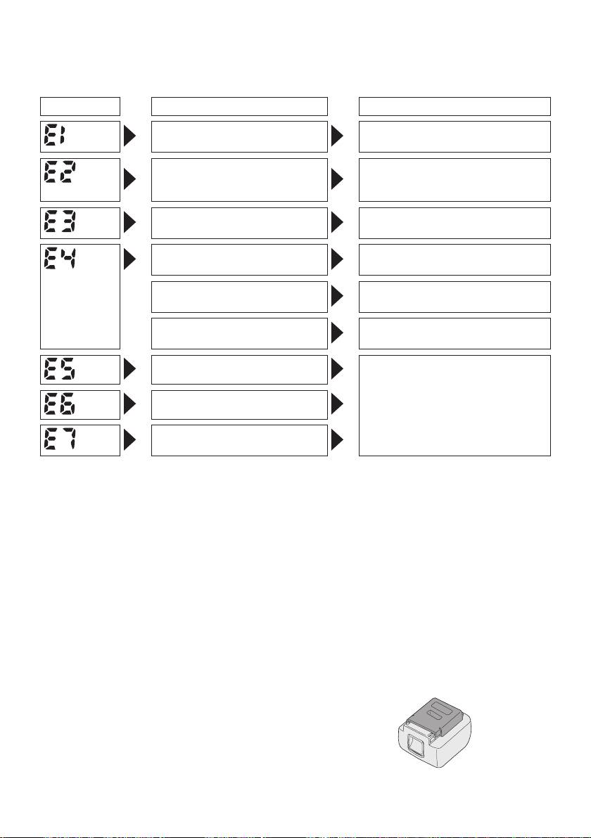
Error Display
In the event of a tool or battery pack malfunction, the control panel will display an error message.
Please check the tool or battery pack as described in the following chart before having them
serviced.
Display Likely cause Corrective action
Setting error Re-initialize the tool using the
remote control. (See page 12.)
The battery pack is too hot. Stop work and allow the battery
pack to cool before resuming use
of the tool.
The tool is too hot to operate. Stop work and allow the tool to
cool before resuming use.
The contacts that connect the
Remove any dirt.
battery pack and tool are dirty.
The battery pack has not been
Insert the battery pack rmly into
properly inserted into the tool.
the tool.
The pins on either the tool or
Replace the battery pack.
battery pack have worn down.
Motor failure, etc. Stop using the tool immediately.
Sensor malfunction, failure, etc.
Tool circuit malfunction, failure,
etc.
• When battery pack is not in use, keep it
[Battery Pack]
away from other metal objects like: paper
clips, coins, keys, nails, screws, or other
For Appropriate Use of Bat-
small metal objects that can make a con-
tery Pack
nection from one terminal to another.
Shorting
the battery terminals together may
cause sparks, burns or a fire.
Li-ion Battery Pack (EYFB30)
•
When operating the battery pack, make sure
• For optimum battery life, store the Li-ion bat-
the work place is well ventilated.
tery pack following use without charging it.
•
When the battery pack is removed from the
•
When charging the battery pack, confirm
main body of the tool, replace the battery
that the terminals on the battery charger
pack cover immediately in order to prevent
are free of foreign substances such as dust
dust or dirt from contaminating the battery
and water etc. Clean the terminals before
terminals and causing a short circuit.
charging the battery pack if any foreign sub-
stances are found on the terminals.
T
he life of the battery pack terminals may be
affected by foreign substances such as dust
and water etc. during operation.
-
13
-
Battery Pack Life
[Battery Charger]
The rechargeable batteries have a limited life.
If the operation time becomes extremely short
Charging
after recharging, replace the battery pack with
Read the operating manual for Panasonic battery
a new one.
charger for the battery pack before charging.
Battery Recycling
Before charging the battery
ATTENTION:
For environmental protection and recycling
When charging EYFB30:
of materials, be sure that it is disposed of
Charge the battery at a temperature of 5°C
at an ofcially assigned location, if there is
(41°F) to 40°C (104°F).
one in your country.
T
he battery pack cannot be charged at a tem-
perature of less than 5°C (41°F)
. If the tem-
perature of the battery pack is less than 5°C
(41°F), rst remove the battery pack from
the charger and allow it to sit for an hour in a
location where the temperature is 5°C (41°F) or
warmer. Then charge the battery pack again.
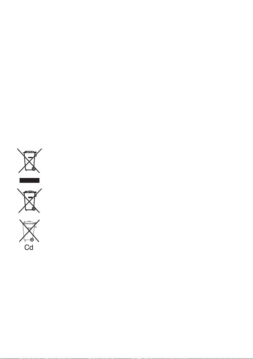
Information for Users on Collection and Disposal of Old Equip-
ment and used Batteries
These symbols on the products, packaging, and/or accompanying documents
mean that used electrical and electronic products and batteries should not be
mixed with general household waste.
F
or proper treatment, recovery and recycling of old products and used batteries,
please take them to applicable collection points, in accordance with your national
legislation and the Directives 2002/96/EC and 2006/66/EC.
By disposing of these products and batteries correctly, you will help to save valuable
resources and prevent any potential negative effects on human health and the
e
nvironment which could otherwise arise from inappropriate waste handling.
For more information about collection and recycling of old products and batteries,
please contact your local municipality, your waste disposal service or the point of
sale where you purchased the items.
P
enalties may be applicable for incorrect disposal of this waste, in accordance with
national legislation.
For business users in the European Union
If you wish to discard electrical and electronic equipment, please contact your dealer or
supplier for further information.
[Information on Disposal in other Countries outside the Euro-
pean Union]
These symbols are only valid in the European Union. If you wish to discard these items,
please contact your local authorities or dealer and ask for the correct method of disposal.
Note for the battery symbol (bottom two symbol examples):
This symbol might be used in combination with a chemical symbol. In this case it complies
with the requirement set by the Directive for the chemical involved.
-
14
-
