Panasonic TYTP60P30K: Maintenance
Maintenance: Panasonic TYTP60P30K
Maintenance
Setup location
Places where the touch panel should not be setup include:
• Locations exposed to direct sunlight, and locations near powerful light sources
(The equipment is an optical touch panel utilizing infrared rays and may function incorrectly when adversely affected.)
• Dusty or humid locations
• Locations that may be exposed to impact or vibration
• Locations near emissions of chemicals or steam, or locations where contact may be made with chemicals
• Locations near sources of electrical noise (generators, air conditioners etc.)
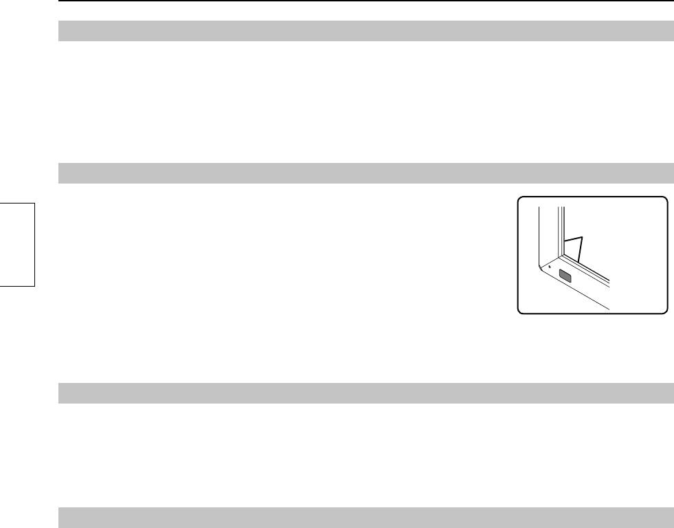
Cautions when in use
Do not touch the infrared transmissive area and screen until the OS starts up after
Infrared
the computer is turned on.
transmissive
• Such an action will be detected as defective elements resulting in malfunction of the
area
equipment. Should this occur, restart the computer. Also when disconnecting and
connecting the USB cable, do not touch the infrared transmissive area and screen.
English
When using other devices utilizing infrared rays, keep them away from the
equipment to prevent erroneous operation.
Use only the touch pen included with this equipment. Operation is not guaranteed
with other products.
When using the touch panel, be careful not to apply an excessive load to it by
pressing the touch panel body or in any other way.
Cautions when moving
Keep the equipment away from any impact when moving. Failure to do so may result in failure.
Hold the main device when moving.
• Gripping this equipment to move may result in failure.
Do not hold the USB cable when moving.
• Doing so may damage the USB cable resulting in a failure.
Maintenance
* Be sure to unplug the USB cable before cleaning the equipment.
Use a soft cloth and lightly wipe off dirt on the surface of the equipment.
• If soiling is severe, wet a cloth in neutral detergent diluted by 100 times with water, wring well, wipe off the soiled part, and
then wipe well with a dry cloth.
• If liquid droplets get inside, the equipment as well as the screen of the main device may fail. Also do not rub up the screen
with strong force.
Use a soft cloth and wipe off dirt on the surface of the infrared transmissive area.
• Once a day, use a soft cloth to wipe off any soiling or debris on the infrared transmissive area. Failure to do so will cause a
malfunction, but on such an occurrence you can restore normal function simply by gently wiping the soiling off.
• If soiling is severe, wet a cloth in neutral detergent diluted by 100 times of water, wring well, wipe off the soiled part, and then
wipe well with a dry cloth.
Do not directly spray or apply detergent.
• If liquid droplets get inside, the equipment may fail.
Do not apply volatile materials such as insecticides, benzene or thinner.
• The panel may get deteriorated or the coating may come off.
Do not keep the equipment contacted with rubber or plastic materials for a long time.
• The cabinet may get deteriorated.
• When using a chemical wipe, follow the instructions supplied with it.
Cleaning of the inside should be performed at least once a year. Consult your dealer for cleaning.
• If dust builds up inside, the level of infrared light available for touch detection will decrease and may result in poor operation.
Consult your dealer for cleaning of the inside at least once a year.
26
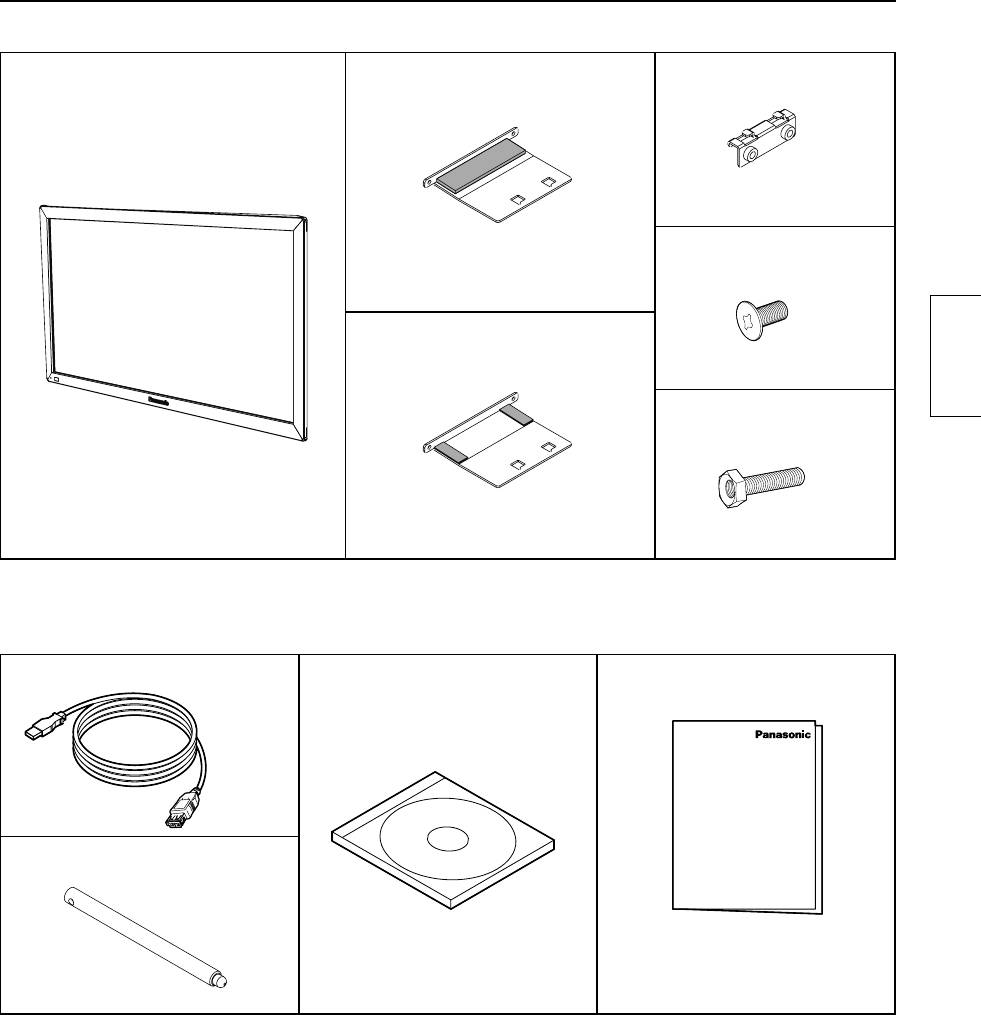
Components
(Check the components and their quantities.)
Touch panel (1)
Mounting bracket A
Mounting bracket B (4)
(for top side) (2)
Mounting screw A (8)
Mounting bracket A
(for bottom side) (2)
English
Mounting screw B (8)
Accessories
USB extension cable (1)
CD-ROM (1)
Operating Instructions
(1)
•
Operating Instructions
•
Driver software
Touch pen (2)
■
Illustrations are conceptual views and may differ in shape from the actual equipment.
■
The specifications of the product are subject to change without notice.
•
Windows is a registered trademark of Microsoft Corporation in the USA and other countries.
®
®
(The official name of Windows is Microsoft
Windows
Operating System.)
•
The names of other companies and products appearing in this publication are the trademarks,
registered trademarks or products names of their respective owners.
27
Touch Panel Assembly
Note
•
Place the touch panel making its front surface face down on a clean cloth or blanket to prevent the front
surface of the touch panel from getting scratched or dirty during work.
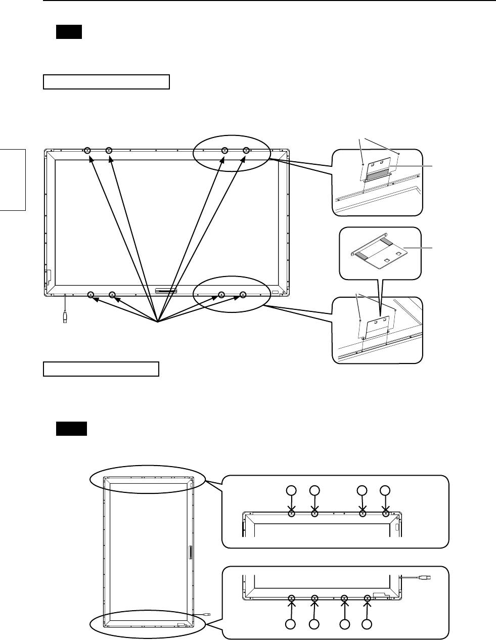
Mounting in horizontal posture
Attach the mounting brackets A (for top and bottom sides) to the touch panel with the mounting screws A (2 each).
See the fi gure below for the screw holes of attachment positions.
The procedure for vertical posture is the same.
Mounting screw A
Mounting
bracket A
(for top side)
English
Mounting
bracket A
(for bottom
side)
Mounting screw A
Attachment positions
(8 holes without screws in them)
Mounting in vertical posture
Check in the fi gure below the positions where the brackets are attached, and remove the screws (8 in total from top and bottom sides).
Attach the mounting brackets A (for top and bottom sides) with the mounting screws A (2 each) to the screw
holes from which the screws were removed.
Notes
•
For screw holes of other models than 42V, see “Drawing of Screw Holes” (page 33).
•
Keep the screws which were removed.
Top side (42V)
123456
Bottom side (42V)
1
2
3
4
5
28
Mounting Touch Panel
Notes
•
Two or more people are always required for mounting.
•
Never mount the main device in the way that is overlapped from above the touch panel while the touch
panel is laid down.
Doing so may damage the touch panel.
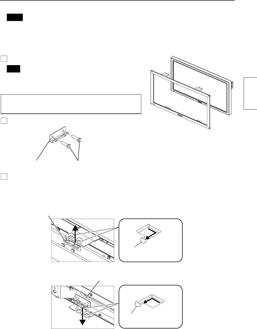
1
Fit the assembled touch panel from the front side of the main device.
Note
•
There should not be a space between the touch panel and the
front surface of main device.
The procedure for vertical posture is the same.
English
Mount in the way that the USB port becomes lower left when
seen from the front.
2
Prepare the mounting brackets B.
Mounting bracket B
Temporarily fix the mounting screws B. (2 or 3 turns)
3
As shown in the figure below, attach the mounting brackets B to the mounting brackets A (for top side) on
the left and right of the top side.
Temporarily fix the screws.
Attach on the left and right of the bottom side in the same way.
Attaching to the top side
Mounting bracket B
Securely insert the projection of the
mounting bracket B to the cutout.
Attaching to the bottom side
Mounting bracket B
Securely insert the projection of the
mounting bracket B to the cutout.
29
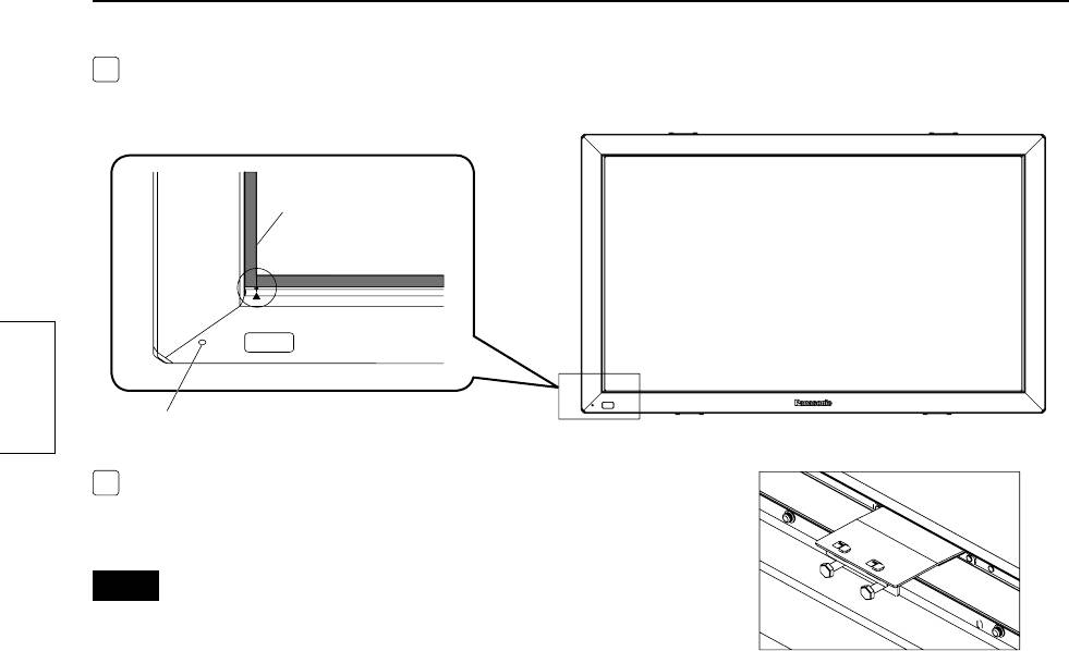
4
Referring to the alignment mark shown in the figure below, adjust the position seeing from the front so that
the touch panel does not lean to one side.
End of the screen
Touch panel
alignment mark
English
Power lamp window
5
After adjusting the position, completely tighten the screws which
were temporarily fixed.
•
Note that tightening the screws too tight may deform the bracket.
Notes
•
There should not be a space between the touch panel and the front
surface of the main device.
•
Confi rm that lighting of the power lamp can be seen from the power
lamp window. If it cannot be seen due to misalignment, move the
touch panel horizontally to make fi ne adjustment.
30
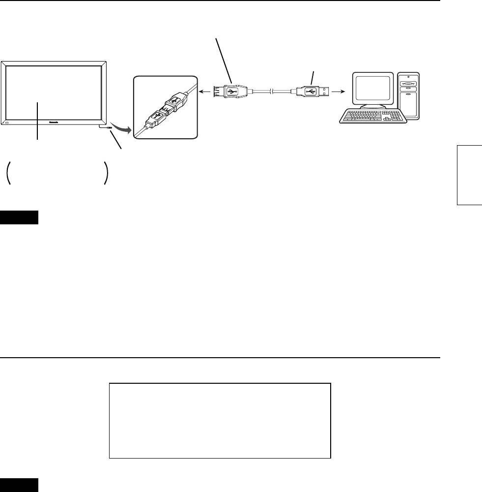
Connection with Computer
USB connector type A
USB connector type A
(Female)
(Male)
Connect to the
Touch panel
USB port on
your computer.
Computer
Main device
USB connector type A
To connect to your computer,
(Male)
see the instruction manual of
the main device.
English
Caution
•
If the infrared transmissive part on the screen is shaded by your fi ngers or other things when connecting the
USB extension cable, that may be detected as a failure during initialization and, if no corrective action is taken,
touch detection may not correctly function partially.
In that case, disconnect and reconnect the USB extension cable. At this time, restarting the computer is not
necessary.
•
Because some cables may not ensure the proper functioning of the equipment, use the USB extension cable
supplied with the equipment.
Operating Conditions
OS of computer
IBM PC/AT compatible machine with USB ports,
supporting the OS below
Windows XP (SP2 or later, 32 bit or 64 bit)
Windows Vista (32 bit or 64 bit)
Windows 7 (SP1 or later, 32 bit or 64 bit)
Caution
•
The USB ports should function correctly.
•
If a previous version of driver has been installed, disconnect the USB cable of the touch panel from the
computer, uninstall the previous version, and then install the new one.
•
For installation and uninstallation of the touch panel driver, see the installation manual of the touch panel driver
software included in the supplied CD-ROM.
•
When using Windows 7, installation of the touch panel driver is not necessary.
When using Windows XP or Vista, follow the descriptions of the installation manual of the driver software
included in the supplied CD-ROM for connection of the USB extension cable and setup of the touch panel
driver software.
31
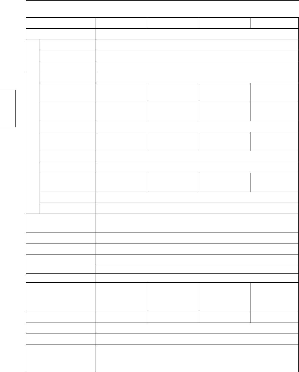
Specifi cations
Model Number TY-TP42P30K TY-TP50P30K TY-TP60P30K TY-TP65P30K
Type Touch Panel
Voltage +5V DC±10%
Electric current +5V DC Max. 500 mA
Supply method From USB bus
Power source
Detection system Infrared ray interruption detection
934.1 mm (W) ×
1124.1 mm (W) ×
1348.1 mm (W) ×
1468.1 mm (W) ×
Panel window
524.1 mm (H)
638.1 mm (H)
766.1 mm (H)
839.1 mm (H)
925 mm (W) ×
1105 mm (W) ×
1330 mm (W) ×
1435 mm (W) ×
Detection range
520 mm (H)
615 mm (H)
750 mm (H)
805 mm (H)
English
Effective detection range
Above detection range + 1.0 mm around all sides
1481 (W) ×
1769 (W) ×
2129 (W) ×
2297 (W) ×
Resolution
833 (H)
985 (H)
1201 (H)
1289 (H)
Touch Panel
Detection pitch 2.5 mm × 2.5 mm
Output system Coordinate output
Number of optical
186 (W) ×
222 (W) ×
267 (W) ×
288 (W) ×
elements
105 (H)
124 (H)
151 (H)
162 (H)
Optical element pitch
5.0 mm (W) × 5.0 mm (H)
Minimum stylus 7.0 mm (W) × 7.0 mm (H)
USB1.1 compliant
Interface
Signals: +DATA, -DATA, VCC, GND
*1
Temperature When operating: 0 ~ 40°C (Temperature gradient 25°C /Hr or less)
1
Humidity When operating: 20 ~ 80% (No dewing) *
Resistance to external
Lateral light 2000 lx or higher (20° angle of incidence)
light
Frontal light 10000 lx or higher (90° angle of incidence)
Panel shape Flat panel (Flat type)
External dimensions
1,028.2 mm (W) ×
1,218.2 mm (W) ×
1,442.2 mm (W) ×
1,562.2 mm (W) ×
(excluding projections and
618.2 mm (H) ×
732.2 mm (H) ×
860.2 mm (H) ×
933.2 mm (H) ×
mounting brackets)
12 mm (D)
12 mm (D)
12 mm (D)
12 mm (D)
Mass Approx. 2.4 kg Approx. 2.7 kg Approx. 3.1 kg Approx. 3.3 kg
Escutcheon material Aluminum
Computer IBM PC/AT compatible machine with USB ports
Windows XP (SP2 or later, 32 bit or 64 bit)
OS
Windows Vista (32 bit or 64 bit)
Windows 7 (SP1 or later, 32 bit or 64 bit)
*1 For the touch panel only (when mounted to the main device, it follows the conditions of the main device.)
32
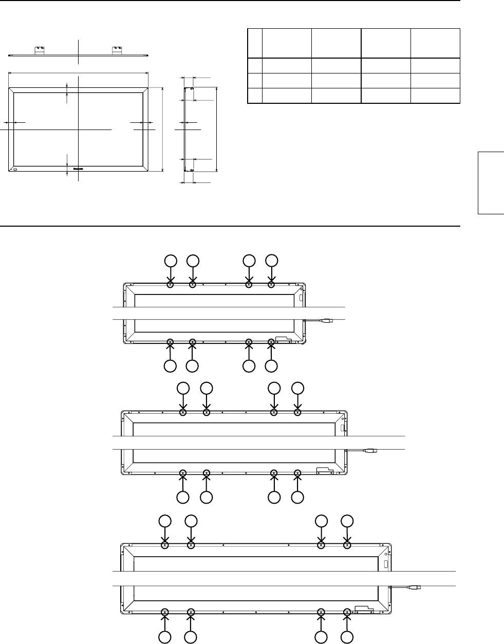
External Dimensions
External Dimensions
(Unit: mm)
Table of external dimensions
(Unit: mm)
42V 50V 60V 65V
A
A 1028.2 1218.2 1442.2 1562.2
79.2
B 618.2 732.2 860.2 933.2
*(89)
C 621.4 735.4 863.4 936.4
47
47
47
12
B
C
* The dimensions may vary depending on the
*(89)
device to be mounted to or the status of tightening.
47
79.2
English
Drawing of Screw Holes
(Mounting in vertical posture)
•
Refer to page 28 for 42V.
123456
For 50V
Top
Bottom
1234 56
12
34
56
7
8
9
For 60V
Top
Bottom
1
23
45
67
12
34
56
For 65V
Top
Bottom
12 3 4 5 67
33
English
Customer’s Record
The model number and serial number of this product can be found on its bottom side. You should
note this serial number in the space provided below and retain this book, plus your purchase
receipt, as a permanent record of your purchase to aid in identifi cation in the event of theft or loss,
and for Warranty Service purposes. Warranty conditions are managed by distributors to meet the
standards set by each country. For details, contact your dealer where you made your purchase.
Model Number Serial Number
Pursuant to at the directive 2004/108/EC, article 9(2)
Panasonic Testing Centre
Web Site : http://panasonic.net
Panasonic Service Europe, a division of
© Panasonic Corporation 2012
Panasonic Marketing Europe GmbH
Winsbergring 15, 22525 Hamburg, F.R. Germany
Printed in Japan
34
