Pioneer SVM-1000: NAMES AND FUNCTIONS OF PARTS
NAMES AND FUNCTIONS OF PARTS: Pioneer SVM-1000
01_SVM-1000_En.book 6 ページ 2007年10月16日 火曜日 午前9時22分
NAMES AND FUNCTIONS OF PARTS
NAMES AND FUNCTIONS OF PARTS
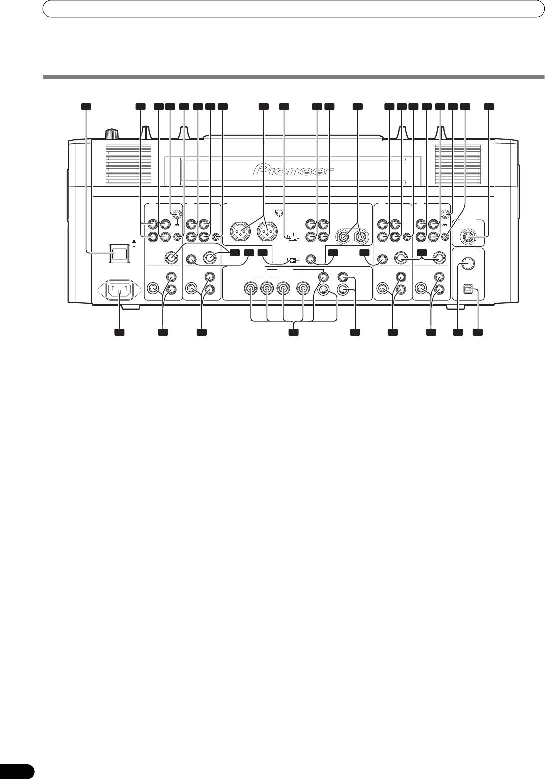
CONNECTION PANEL
1
2 3 4 95 6 7 10 11
8 12
2 3 4 555 6 7 13
4 3
SIGNAL GND
AUDIO OUT
1 GND 2 HOT
21
SIGNAL GND
MASTER
REC
PHONO
DVD/LINE LINE
DVD
MASTER OUT 1
OUT 2
OUT
BOOTH
LINE
DVD PHONO
DVD/LINE
R
L
3 COLD
MONITOR
L
L
MASTER
L
(TRS)
LR
L
L
MIC2
ATT.
CONTROL
CONTROL
-6 dB 0 dB
-3 dB
CONTROL
CONTROL
R
R
R
R
R
POWER
OFF
ON
SYNC
SYNC
SYNC
SYNC
OUT
DIGITAL
OUT
DIGITAL OUT
DIGITAL
OUT
OUT
IN
fs (Hz)
IN
MIDI
14 15 16 17 15 14
48 k 96 k
OUT
DVD
DVD
VIDEO OUT
MASTER
MONITOR
DVD
DVD
AC IN
S-VIDEO
S-VIDEO
COMPONENT COMPOSITE
USB
YC
B CR
S-VIDEO
S-VIDEO
VIDEO
VIDEO
S-VIDEO S-VIDEO
VIDEO
VIDEO
18 19 19 19 1921 232220
1 POWER switch
11 Recording output connectors (REC OUT)
2 PHONO input connectors
RCA type output connectors for recording.
RCA type phono level (MM cartridge) input connectors.
12 BOOTH MONITOR output jacks (TRS)
Do not use for inputting line level signals.
Ø 6.3 mm phone-type booth monitor output jacks.
3 DVD/LINE input connectors
The sound level output at these connectors can be controlled by
RCA type line level audio input connectors.
the BOOTH MONITOR level dial, regardless of the setting of the
Use to connect a DJ/VJ DVD player or DJ CD player or other line
MASTER LEVEL dial. (Since the output is TRS, both balanced and
level output component.
unbalanced outputs are supported.)
4 Signal ground terminal (SIGNAL GND)
13 Microphone 2 input jack (MIC 2)
Connect the ground wire from an analog turntable.
Connect microphones equipped with phone-type plug.
This is not a safety ground terminal.
14 Sync signal output connector (SYNC OUT)
5 CONTROL connector
Outputs video sync signal.
Connect the Ø 3.5 mm mini phone plug of the control cable from
When connecting a Pioneer DJ/VJ DVD player (sold separately),
a DJ/VJ DVD player or DJ CD player.
the sync signal helps suppress any lag between video and audio
When this is done, this mixer’s fader controls can be used to
signals.
perform start and back-cue functions on the connected DJ/VJ DVD
15 Digital input connector (DIGITAL IN)
player or DJ CD player.
RCA-type digital coaxial input connector. Connect to the digital
6 LINE input connectors
coaxial output connector from a DJ/VJ DVD player or DJ CD player.
RCA type line level audio input connectors.
• If the sampling frequency of the output signal changes, the
Use to connect a cassette deck or other line level output
sound may be interrupted briefly.
component.
16 Sampling frequency selector switch (fs 48 k/96 k)
7 DVD input connectors
Use to set the sampling frequency of the digital output to 96 kHz/
RCA type line level audio input connectors.
24-bit format or 48 kHz/24-bit format.
Use to connect a DJ/VJ DVD player or DJ CD player or other line
Turn power off before changing this switch position.
level output component.
17 Digital output connector (DIGITAL OUT)
8 Audio master output 1 connectors (MASTER OUT 1)
RCA type digital coaxial output connector.
XLR type (male) balanced output.
Master audio digital output.
• When using a cord with RCA-type plug, users are recommended
18 Power inlet (AC IN)
to connect the plug directly to the MASTER OUT 2 connectors
Use the furnished power cable to connect to a household AC
without using an XLR/RCA converter plug.
outlet.
When a conversion plug is used, the signal GND may become
19 Video input connectors (DVD, VIDEO, S-VIDEO)
unstable, in rare cases resulting in the production of noise.
Composite and S-VIDEO type video input connectors.
9 Audio master output attenuator selector (MASTER ATT.)
20 Video master output connectors
Attenuates the output level of the audio master 1 and audio master
(MASTER: COMPONENT, COMPOSITE, S-VIDEO)
2.
Component, composite, and S-VIDEO type video output
Attenuation level can be selected as 0 dB, –3 dB, or –6 dB.
connectors.
10 Audio master output 2 connectors (
MASTER OUT 2
)
21 Video monitor output connectors (MONITOR, S-VIDEO)
RCA-type unbalanced output.
Composite and S-VIDEO type monitor video output connectors.
6
En
01_SVM-1000_En.book 7 ページ 2007年10月16日 火曜日 午前9時22分
NAMES AND FUNCTIONS OF PARTS
22 MIDI OUT connector
23 MIDI USB output connector
DIN type output connector.
USB-B type output connector. Use to connect to a computer.
Use to connect to other MIDI component.
English
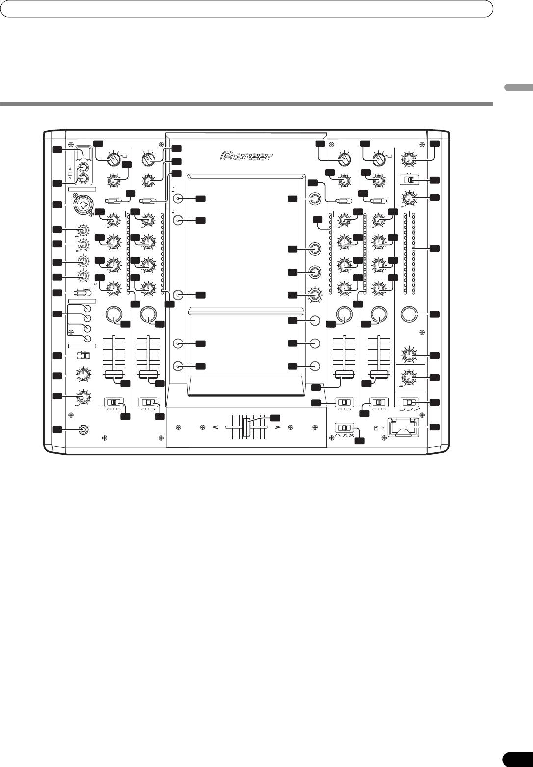
OPERATION PANEL
14 16 17 32
VIDEO INPUT
VIDEO INPUT
VIDEO INPUT
VIDEO INPUT
VIDEO
DVD
VIDEO
S-VIDEO
DVD
VIDEO
S-VIDEO
15
DVD
VIDEO
S-VIDEO
DVD
VIDEO
MASTER LEVEL
1
S-VIDEO
USB
VIDEO
VIDEO
EX
EX
CH 1
18
18
WHITEBLACK
VIDEO
VIDEO TRIM
VIDEO TRIM
VIDEO TRIM
VIDEO TRIM
EX
MONO STEREO
20
18 18
CH 4
33
2
UTILITY
21
MIC
MIN
MAX
MIN
MAX
MONITOR
MASTER
CH SELECT
MIN
MAX
MIN
MAX
AUDIO MASTER LEVEL
AUDIO INPUT
AUDIO INPUT
SET UP
AUDIO INPUT
DVD/LINE PHONO
19 22
AUDIO INPUT
DVD LINE DIGITAL
DVD LINE DIGITAL
LINE PHONO
40
45
34
3
AUDIO TRIM
OVER
AUDIO TRIM
VIDEO EQ
ON/OFF
OVER
AUDIO TRIM
0
OVER
OVER
AUDIO TRIM
OVER
SET UP
MIC 1
23 23
23
23
27
MIC1
10
10
41
10
10
10
LEVEL
+9
7
+9
7
7
+9
7
+9
7
4
HI
4
HI
4
4
HI
4
HI
4
MIC2
0
VIDEO FX
2
2
2
LEVEL
24 24
PATTERN/
2
24
24
2
1
1
TEXT BANK
1
1
1
5
0
0
0
0
0
0
+6-26
+6-26
46
+6-26
+6-26
35
MID
–1
MID
–1
–1
MID
–1
MID
–1
HI
–2
–2
TIME/
–2
–2
–2
6
25 25
–3
–3
PARAMETER
–3
25
–3
25
–3
-12
+12
LOW
–5
–5
–5
–5
–5
+6-26
–7
+6-26
–7
47
–7
+6-26
–7
+6-26
–7
7
26
LOW
–10
26
LOW
–10
–10
LOW
-12
+12
26
–10
LOW
26
LEVEL/
–10
MIC OFF ON
TALK
OVER
–15
–15
JPEG
DEPTH
–15
–15
–15
–24
–24
VIEWER
–24
–24
–24
8
+6-26
dB
+6-26
dB
42
48
dB
+6-26
dB
+6-26
dBLR
FADER START
2727
MAXMIN
27
CH1
EFFECT
9
CUE
CUE
CUE
CUE
CUE
CUE
CH2
28
28
28
28
28
28
CH3
MASTER
1
2
VIDEO
3
4
10
10
SOLO MODE
CH4
10
10
9
9
9
9
HEAD PHONES
8
8
43
49
8
8
BALANCE
MONO SPLIT STEREO
7
7
7
7
6
6
10
5
5
FADER
EFFECT
6
6
AV SYNC
ON/OFF
5
5
36
4
4
4
4
MIXING
3
3
3
3
RL
2
2
44
50
2
2
BOOTH MONITOR
1
1
1
1
0
0
0
0
11
37
CUE
MASTER
LEVEL
29
29
29
0
CROSS FADER
CROSS FADER
29
CROSS FADER
CROSS FADER
ASSIGN
ASSIGN
ASSIGN
ASSIGN
CH FADER CURVE
12
0
30
38
A THRU B
A THRU B
A THRU B
A THRU B
30
30
30
PHONES
51
CROSS FADER CURVE SD CARD
PROFESSIONAL SOUND
&
VISION MIXER
AB
39
13
SVM-1000
31
1 USB connector
8 Microphone function selector switch (MIC)
Use to connect a USB memory or keyboard.
OFF:
No microphone sound is output.
2 CH1/CH4 video input connectors (VIDEO EX)
Use to input video from an external source.
ON:
Microphone sounds are output, and the microphone function
3 Microphone 1 input jack (MIC 1)
indicator lights.
Connect microphone with XLR-type or phone-type plug.
TALK OVER:
4 Microphone 1 level control dial (MIC 1 LEVEL)
Microphone sounds are output, and the microphone function
Use to adjust the volume of microphone 1. (Adjustable range –∞ to
indicator flashes.
0dB)
When an audio signal of –15 dB or more (default setting) is input
5 Microphone 2 level control dial (MIC 2 LEVEL)
to the microphone input, the talkover function operates to reduce
Use to adjust the volume of microphone 2. (Adjustable range –∞ to
all output other than the mike audio by 20 dB (default setting).
0dB)
Values can be changed in the hardware setup (P. 42)
6 Microphone equalizer high-range adjust dial (HI)
• When not using the TALK OVER function, it is recommended to
Use to adjust the treble (high-range) frequencies of microphones 1
set the switch to the [OFF] or [ON] position.
and 2. (Adjustable range –12 dB to +12 dB)
9 FADER START button/indicator (CH-1 to CH-4)
7 Microphone equalizer low-range adjust dial (LOW)
Enables the fader start/back cue function for the channel to which
Use to adjust the bass (low-range) frequencies of microphones 1
a DJ/VJ DVD player or DJ CD player is connected. The button lights
and 2. (Adjustable range –12 dB to +12 dB)
when set to ON. When enabled, the operation differs depending on
the setting of the CROSS FADER ASSIGN switch.
•When the CROSS FADER ASSIGN switch is set to the [A] or [B]
position, FADER START button operation is linked to the
operation of the cross fader (and unlinked to channel fader).
•When the CROSS FADER ASSIGN switch is set to the [THRU]
position, FADER START button operation is linked to the
operation of the channel fader (and unlinked to cross fader).
7
En

01_SVM-1000_En.book 8 ページ 2007年10月16日 火曜日 午前9時22分
NAMES AND FUNCTIONS OF PARTS
10 HEADPHONES output switch (MONO SPLIT/STEREO)
24 Channel equalizer high-range adjust dial (HI)
MONO SPLIT:
Use to adjust the treble (high-range) frequency sound for each
The source sound selected with the headphone CUE button is
channel. Video parameters can also be assigned. See P. 34
output to the L channel, while the master sound is output to the R
regarding video parameters. (Adjustable range: –26 dB to +6 dB)
channel (only when [MASTER] is selected with the headphone
25 Channel equalizer mid-range adjust dial (MID)
CUE button).
Use to adjust the mid-range frequency sound for each channel.
STEREO:
Video parameters can also be assigned. See P. 34 regarding video
The audio source selected with the headphone CUE button is
parameters. (Adjustable range: –26 dB to +6 dB)
output in stereo.
26 Channel equalizer low-range adjust dial (LOW)
11 HEADPHONES MIXING dial
Use to adjust the bass (low-range) frequency sound for each
When rotated clockwise (toward [MASTER]), the master output
channel. Video parameters can also be assigned. See P. 34
audio is produced at the headphones (only when [MASTER] has
regarding video parameters. (Adjustable range: –26 dB to +6 dB)
been selected with the headphone CUE button); when rotated
27 Channel level indicator
counterclockwise (toward [CUE]), the headphones output
Displays the current level for each channel, with two-second peak
becomes the mixture of the effect monitor and the channel
hold.
selected with the headphone CUE button.
28 Headphone
CUE
buttons/indicators
12 HEADPHONES LEVEL adjust dial
These buttons are used to select from 1 to 4, MASTER, or
Adjusts the output level of the headphones jack. (Adjustable
EFFECT CUE, to allow you to monitor the desired source through
range: –∞ to 0 dB)
headphones. If multiple buttons are pressed simultaneously, the
13 Headphones jack (PHONES)
selected audio sources are mixed. Press the button once more to
14 Channel 1 VIDEO INPUT selector switch
cancel the selected source. Unselected buttons glow darkly, while
Set to [DVD], [VIDEO], [S-VIDEO], or [VIDEO EX] to match the
selected source buttons light brightly.
type of input connected.
29 Channel fader lever
15 Channel 2 VIDEO INPUT selector switch
Use to adjust sound volumes and video level for each channel.
Set to [DVD], [VIDEO], or [S-VIDEO] to match the type of input
(Adjustable range: –∞ to 0 dB)
connected.
Output is in accordance with the channel fader curve selected
16 Channel 3 VIDEO INPUT selector switch
with the CH FADER CURVE switch.
Set to [DVD], [VIDEO], or [S-VIDEO] to match the type of input
30 CROSS FADER ASSIGN switch
connected.
This switch assigns each channel’s output to either right or left
17 Channel 4 VIDEO INPUT selector switch
side of the cross fader (if multiple channels are assigned to the
Set to [DVD], [VIDEO], [S-VIDEO], or [VIDEO EX] to match the
same side, the result will be the combined sum of the channels).
type of input connected.
A:
The selected channel is assigned to the cross fader’s [A] (left) side.
18 VIDEO TRIM dial
Use to adjust the level of the video input signal for each channel.
THRU:
The channel fader’s output is sent as is to the master output,
• When rotated counterclockwise, the luminance level is reduced,
without being passed through the cross fader.
eventually producing a black screen.
B:
• When rotated clockwise, the luminance level is raised,
The selected channel is assigned to the cross fader’s [B] (right)
eventually producing a white screen.
side.
• At the center position, the luminance level is neutral (same level
31 CROSS FADER CURVE switch
as input).
This switch allows the user to select from three types of cross fader
19 Channel 1 AUDIO INPUT selector switch
curve response.
DVD/LINE:
• At the left setting, the curve produces a rapid signal rise. (As
Use to select DVD/LINE input connectors (line level analog input).
soon as the cross fader lever leaves the [A] side, the [B] channel
PHONO:
sound is produced.)
Use to select
PHONO input connectors (analog turntable input).
• At the right setting, the curve operates to produce an even,
20 Channel 2 AUDIO INPUT selector switch
neutral rise throughout the cross fader’s movement.
DVD:
• At the middle setting, an intermediate curve is produced,
Use to select DVD input connectors.
midway between the two curves noted above.
LINE:
32 Video master output level dial (VIDEO MASTER LEVEL)
Use to select LINE input connectors (line level analog input).
Adjusts the video master output luminance level.
DIGITAL:
Use to select DIGITAL input connector.
33 Master output MONO/STEREO selector switch
When set to the [MONO] position, audio master output is
21 Channel 3 AUDIO INPUT selector switch
produced in L+R monaural.
DVD:
Use to select DVD input connectors.
34 Audio master output level dial (AUDIO MASTER LEVEL)
LINE:
Use to adjust the master output level. (Adjustable range: –∞ to
Use to select LINE input connectors (line level analog input).
0dB)
The master output is the sum combination of the sound from
DIGITAL:
Use to select DIGITAL input connector.
channels set to [THRU] with the CROSS FADER ASSIGN switch;
the signal passed through the cross fader; and the signals from
22 Channel 4 AUDIO INPUT selector switch
microphone 1 and microphone 2.
DVD/LINE:
35 Master level indicator (MASTER L, R)
Use to select DVD/LINE input connectors (line level analog input).
These segment indicators display the audio output level from L and
PHONO:
R channels. The indicators have a two-second peak hold.
Use to select PHONO input connectors (analog turntable input).
36 Master balance dial (BALANCE)
23 AUDIO TRIM dial
Use to adjust the L/R channel balance for audio master output,
Use to adjust the level of the audio input signal for each channel.
booth monitor output, recording output, and digital output.
(Adjustable range: –∞ to +9 dB, mid-position is about 0 dB)
8
En

01_SVM-1000_En.book 9 ページ 2007年10月16日 火曜日 午前9時22分
NAMES AND FUNCTIONS OF PARTS
37 BOOTH MONITOR level control dial
50 Effect button/indicator (EFFECT ON/OFF)
This dial is used to adjust the booth monitor output volume.
Turns selected effect ON/OFF.
The volume can be adjusted independently of the master output
When power is turned ON, the button lights (defaults to effect
level. (Adjustable range: –∞ to 0 dB)
OFF). When effects are enabled (ON), the button flashes.
38 Channel fader curve switch (CH FADER CURVE)
51 Cross fader lever (A/B)
This switch allows the user to select from three types of channel
English
Outputs audio and video assigned to [A] and [B] sides in
fader curve response. This setting is applied equally to channels
accordance with setting of the CROSS FADER ASSIGN switch, and
1to 4.
subject to the cross fader curve selected with the CROSS FADER
• At the left setting, the curve operates to produce a rapid rise as
CURVE switch.
the channel fader approaches its distant position.
• At the right setting, the curve operates to produce an even,
neutral rise throughout the channel fader’s movement.
• At the middle setting, an intermediate curve is produced,
midway between the two curves noted above.
39 SD CARD slot
Insert an SD card with JPEG image files.
40 UTILITY button (MASTER MONITOR, SET UP)
Use to switch the master monitor display ON/OFF.
Hold the button depressed to display the utility setup screen.
The indicator lights when the master monitor is displaying. The
indicator flashes when the setup screen is displayed.
41 VIDEO EQ button (ON/OFF, SET UP)
Use to switch the video equalizer ON/OFF. Hold the button
depressed to display the equalizer setup screen.
The indicator lights when ON, and flashes when in the setup
screen.
42 JPEG VIEWER button
Use to set the JPEG viewer mode. The indicator lights when in the
JPEG viewer mode.
43 VIDEO SOLO MODE button
Use to switch the video solo mode ON/OFF. When the video solo
mode is ON, the indicator will flash.
44 Fader AV synchro button (FADER AV SYNC)
Use to select whether the video processed by the video mix mode
is linked to the audio.
The indicator lights when linked.
45 Effect channel selector dial (CH SELECT)
Use to select the channel to which effects are applied. When [MIC]
is selected, effects are applied to both microphone 1 and
microphone 2.
46 VIDEO FX PATTERN/TEXT BANK dial
Use to select video effects, video effect patterns and text banks.
47 Effect parameter 1 dial (TIME/PARAMETER)
Adjusts parameter for selected effect.
• If this dial is rotated while depressing the TAP button, direct
BPM can be set manually.
48 Effect parameter 2 dial (LEVEL/DEPTH)
Adjusts quantitative parameters for selected effect.
49
TAP
button
The BPM is calculated from the intervals at which the TAP button
is struck.
9
En
Оглавление
- Contents
- CONFIRM FEATURES ACCESSORIES
- NAMES AND FUNCTIONS OF PARTS
- CONNECTIONS
- BASIC OPERATIONS
- USING THE VIDEO FADER FUNCTION
- USING THE EFFECT FUNCTION
- USING THE JPEG VIEWER
- THE VIDEO EQUALIZER FUNCTION
- FADER START FUNCTION
- PERFORM UTILITY SETUP
- HARDWARE SETUP
- TROUBLESHOOTING
- SPECIFICATIONS
- Contenu
- VÉRIFICATION DES CARACTÉRISTIQUES ACCESSOIRES
- NOMS ET FONCTIONS DES ORGANES
- CONNEXIONS
- DÉMARCHES DE BASE
- UTILISATION DE LA FONCTION DE FONDU VIDÉO
- UTILISATION DE LA FONCTION D’EFFET
- UTILISATION DU VISUALISEUR JPEG
- FONCTION D’ÉGALISEUR VIDÉO
- FONCTION DE DÉPART EN FONDU
- EXÉCUTION DE LA CONFIGURATION UTILITAIRE
- CONFIGURATION DU MATÉRIEL
- GUIDE DE DÉPANNAGE
- FICHE TECHNIQUE
- Inhaltsverzeichnis
- ÜBERPRÜFEN DES VORSICHTSHINWEISE MITGELIEFERTEN ZUR HANDHABUNG ZUBEHÖRS
- MERKMALE
- BEZEICHNUNG UND FUNKTION DER BEDIENELEMENTE
- ANSCHLÜSSE
- GRUNDLEGENDE BEDIENUNGSVERFAHREN
- VERWENDUNG DER VIDEOFADER-FUNKTION
- VERWENDUNG DER EFFEKTFUNKTION
- VERWENDUNG DES JPEG VIEWER
- DIE VIDEO EQUALIZER-FUNKTION
- FADER-STARTFUNKTION
- AUSFÜHRUNG DES UTILITY-SETUP
- HARDWARE-SETUP
- STÖRUNGSBESEITIGUNG
- TECHNISCHE DATEN
- Indice
- CONTROLLO DEGLI CARATTERISTICHE ACCESSORI
- NOME DELLE VARIE PARTI E LORO FUNZIONE
- COLLEGAMENTI
- OPERAZIONI DI BASE
- USO DELLA FUNZIONE DI DISSOLVENZA VIDEO
- USO DEGLI EFFETTI
- USO DI JPEG VIEWER
- LA FUNZIONE DI EQUALIZZAZIONE VIDEO
- FUNZIONE DI INIZIO DELLA DISSOLVENZA
- IMPOSTAZIONE DELL'UTILITY DI PERFORMANCE
- IMPOSTAZIONI HARDWARE
- DIAGNOSTICA
- CARATTERISTICHE TECNICHE
- Inhoud
- CONTROLEER DE WAARSCHUWINGEN ACCESSOIRES I.V.M. HET GEBRUIK
- KENMERKEN
- BENAMING EN FUNCTIE VAN DE BEDIENINGSORGANEN
- AANSLUITINGEN
- BASISBEDIENING
- GEBRUIK VAN DE VIDEOFADERFUNCTIE
- GEBRUIK VAN DE EFFECTFUNCTIE
- GEBRUIK VAN DE JPEG VIEWER
- DE VIDEO-EQUALIZER FUNCTIE
- FADERSTARTFUNCTIE
- UTILITY-INSTELLINGEN
- APPARATUUR-INSTELLINGEN
- VERHELPEN VAN STORINGEN
- TECHNISCHE GEGEVENS
- Índice
- CONFIRMACIÓN DE CARACTERÍSTICAS LOS ACCESORIOS
- NOMENCLATURA Y FUNCIONES DE LOS CONTROLES
- CONEXIONES
- OPERACIONES BÁSICAS
- EMPLEO DE LA FUNCIÓN DE FUNDIDO DE VÍDEO
- EMPLEO DE LA FUNCIÓN DE EFECTOS
- EMPLEO DE JPEG VIEWER
- FUNCIÓN DEL ECUALIZADOR DE VÍDEO
- FUNCIÓN DE INICIO CON FUNDIDO
- EFECTÚE LA CONFIGURACIÓN DE UTILIDADES
- CONFIGURACIÓN DE DISPOSITIVOS
- SOLUCIÓN DE PROBLEMAS
- ESPECIFICACIONES
- Содержание
- ПРОВЕРКА НАЛИЧИЯ ФУНКЦИОНАЛЬНЫЕ ПРИНАДЛЕЖНОСТЕЙ ОСОБЕННОСТИ
- ЭЛЕМЕНТЫ УСТРОЙСТВА И ИХ ФУНКЦИИ
- ПОДКЛЮЧЕНИЯ
- ОСНОВНЫЕ ОПЕРАЦИИ
- ПОЛЬЗОВАНИЕ ФУНКЦИЕЙ ВИДЕОФЕЙДЕРА
- ПОЛЬЗОВАНИЕ ФУНКЦИЕЙ НАЛОЖЕНИЯ ЭФФЕКТОВ
- ПОЛЬЗОВАНИЕ ОБОЗРЕВАТЕЛЕМ JPEG (JPEG VIEWER)
- ФУНКЦИЯ ВИДЕОЭКВАЛАЙЗЕРА
- ФУНКЦИЯ ЗАПУСКА ПО ФЕЙДЕРУ
- ВЫПОЛНИТЕ НАСТРОЙКУ ПРОГРАММЫ
- НАСТРОЙКА ОБОРУДОВАНИЯ
- УСТРАНЕНИЕ НЕПОЛАДОК
- ТЕХНИЧЕСКИЕ ХАРАКТЕРИСТИКИ


