Pioneer S-4EX-W: инструкция
Раздел: Бытовая, кухонная техника, электроника и оборудование
Тип: Домашний кинотеатр
Инструкция к Домашнему кинотеатру Pioneer S-4EX-W

http://www.pioneer.co.uk
(or http://www.pioneer.eu)
S-4EX_EN.book 1 ページ 2008年7月16日 水曜日 午後2時2分

Thank you for buying this Pioneer product.
Please read through these operating instructions so you will know how to operate your model properly.
After you have finished reading the instructions, put them away in a safe place for future reference.
Contents
Before you start
Connections
Connecting to an amplifier. . . . . . . . . . . . . . . . . . . . . . . . . . . . . . . .7
What’s in the box
Connecting the cables . . . . . . . . . . . . . . . . . . . . . . . . . . . . . . . . . . .7
Single-Wire Connections. . . . . . . . . . . . . . . . . . . . . . . . . . . . . . . .8
About the EX series
Bi-Wire Connections . . . . . . . . . . . . . . . . . . . . . . . . . . . . . . . . . . .8
Technology behind the S-4EX . . . . . . . . . . . . . . . . . . . . . . . . . . . . . 4
Bi-Amplification Connections . . . . . . . . . . . . . . . . . . . . . . . . . . . .9
CST. . . . . . . . . . . . . . . . . . . . . . . . . . . . . . . . . . . . . . . . . . . . . . . . 4
Ceramic Graphite Diaphragm. . . . . . . . . . . . . . . . . . . . . . . . . . . . 4
Other Information
Magnesium Alloy Diaphragm . . . . . . . . . . . . . . . . . . . . . . . . . . . . 4
Attaching/Removing the Grille Cover . . . . . . . . . . . . . . . . . . . . . . .10
Bass Drivers . . . . . . . . . . . . . . . . . . . . . . . . . . . . . . . . . . . . . . . . . 4
Cleaning the speaker cabinet. . . . . . . . . . . . . . . . . . . . . . . . . . . . .10
Bass Enclosure Construction . . . . . . . . . . . . . . . . . . . . . . . . . . . . 4
Specifications . . . . . . . . . . . . . . . . . . . . . . . . . . . . . . . . . . . . . . . .10
Crossover Networks . . . . . . . . . . . . . . . . . . . . . . . . . . . . . . . . . . . 4
Collaboration with Air Studios . . . . . . . . . . . . . . . . . . . . . . . . . . . 4
Installation and Placement
How to install . . . . . . . . . . . . . . . . . . . . . . . . . . . . . . . . . . . . . . . . . 5
Installing the spikes . . . . . . . . . . . . . . . . . . . . . . . . . . . . . . . . . . . 5
When not using the spikes . . . . . . . . . . . . . . . . . . . . . . . . . . . . . . 5
Choosing Where To Place The Speaker Systems . . . . . . . . . . . . . 6
For U.S. model
2
En
We Want You Listening For A Lifetime
Used wisely, your new sound equipment will
provide a lifetime of fun and enjoyment. Since
hearing damage from loud noise is often
undetectable until it is too late, this manufacturer
and the Electronic Industries Association’s
Selecting fine audio equipment such as the unit
Consumer Electronics Group recommend you avoid
you’ve just purchased is only the start of your
prolonged exposure to excessive noise. This list of
musical enjoyment. Now it’s time to consider how
sound levels is included for your protection.
you can maximize the fun and excitement your
equipment offers. This manufacturer and the
Decibel
Electronic Industries Association’s Consumer
Level Example
Electronics Group want you to get the most out of
your equipment by playing it at a safe level. One that
30 Quiet library, soft whispers
lets the sound come through loud and clear without
40
Living room, refrigerator, bedroom away from traffic
annoying blaring or distortion-and, most importantly,
50 Light traffic, normal conversation, quiet office
without affecting your sensitive hearing.
60 Air conditioner at 20 feet, sewing machine
70 Vacuum cleaner, hair dryer, noisy restaurant
Sound can be deceiving. Over time your hearing
80
Average city traffic, garbage disposals, alarm clock
“comfort level” adapts to higher volumes of sound.
at two feet.
So what sounds “normal” can actually be loud and
harmful to your hearing. Guard against this by
THE FOLLOWING NOISES CAN BE DANGEROUS
setting your equipment at a safe level BEFORE your
UNDER CONSTANT EXPOSURE
hearing adapts.
90
Subway, motorcycle, truck traffic, lawn mower
To establish a safe level:
100 Garbage truck, chain saw, pneumatic drill
• Start your volume control at a low setting.
120 Rock band concert in front of speakers,
• Slowly increase the sound until you can hear it
thunderclap
comfortably and clearly, and without distortion.
140 Gunshot blast, jet plane
180 Rocket launching pad
Once you have established a comfortable sound
level:
Information courtesy of the Deafness Research Foundation.
• Set the dial and leave it there.
Taking a minute to do this now will help to prevent
hearing damage or loss in the future. After all, we
want you listening for a lifetime.
S001_En
S-4EX_EN.book 2 ページ 2008年7月16日 水曜日 午後2時2分
Before you start
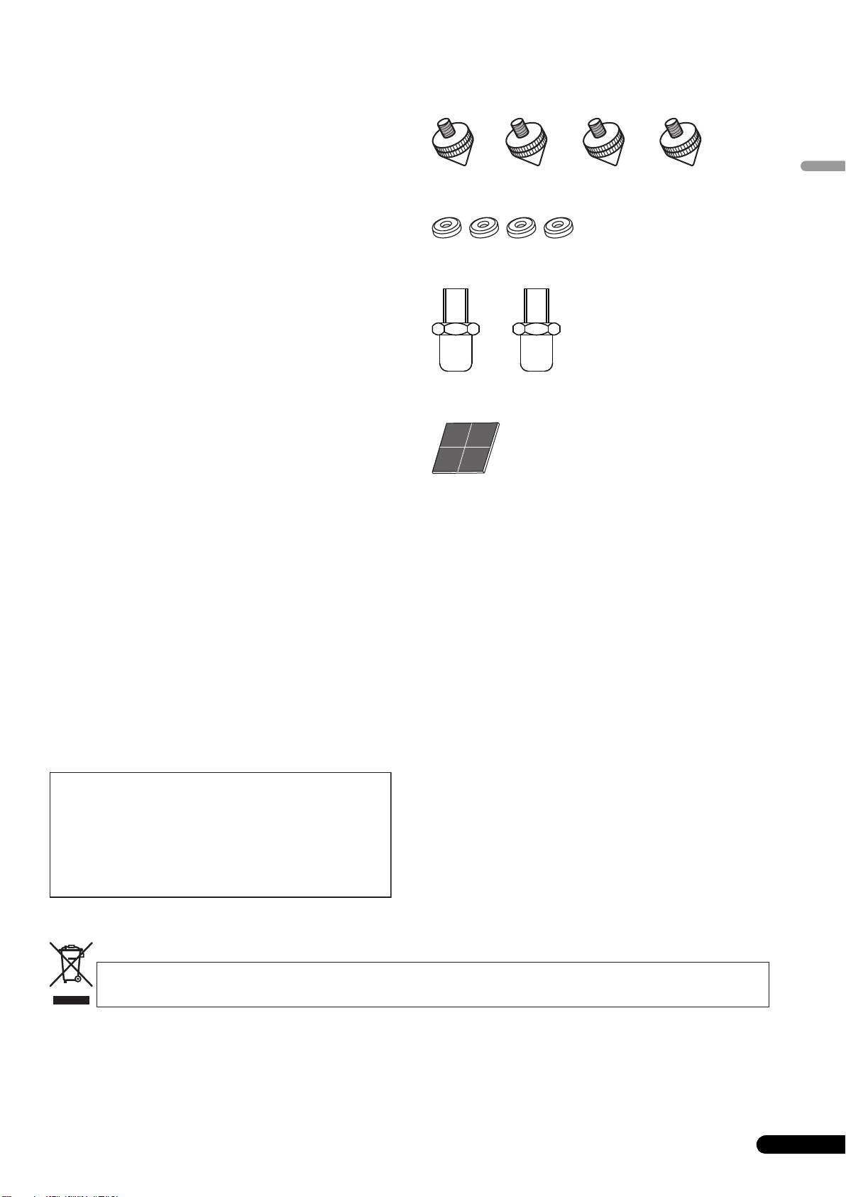
What’s in the box
• The nominal impedance of this speaker system is 6 Ω.
Connect the speaker system to an amplifier with a load
impedance ranging from 6 Ω to 16 Ω (a model with “6 Ω –
16 Ω” displayed on the speaker output terminals).
In order to prevent damage to the speaker system resulting
English
Spikes (with attached nuts) x 4
from input overload, please observe the following precautions:
• Do not supply power to the speaker system in excess of the
maximum permissible input.
• When using a graphic equalizer to emphasize loud sounds in
Spike bases x 4
the high-frequency range, do not use excessive amplifier
volume.
• Do not try to force a low-powered amplifier to produce loud
volumes of sound (the amplifier’s harmonic distortion will be
increased, and you may damage the speaker).
Caution: installation
• When placing this unit, ensure that it is firmly secured and
avoid areas where it may be likely to fall and cause injury in the
Auxiliary feet x 2
event of a natural disaster (such as an earthquake).
• Do not attach these speakers to the wall or ceiling. They may
fall off and cause injury.
• Do not install your speakers overhead on the ceiling or wall. If
improperly attached, the speaker grille can fall and cause
damage or personal injury.
• Switch off and unplug your AV equipment and consult the
Non-skid pads x 4
instructions when connecting up components. Make sure you
use the correct connecting cables.
Grille x 1
Operating instructions
Caution: in use
• Do not place the speaker on an unstable surface. It could
present a hazard if it falls, as well as damaging the equipment.
• Do not use the speaker to output distorted sound for long
periods of times. This can result in a fire hazard.
• Do not sit or stand on the speaker, or let children play on the
speaker.
• Do not put large or heavy objects on top of the speaker.
• Do not place magnetic objects such as screwdrivers or iron
parts near the tweeter or midrange. Since the speakers use
strong magnets, the objects may be attracted, causing injury
or damaging the diaphragm.
For U.S. model
For European model
3
En
WARNING: Handling the cord on this product or
cords associated with accessories sold with the
product will expose you to chemicals listed on
proposition 65 known to the State of California and
other governmental entities to cause cancer and
birth defect or other reproductive harm.
Wash hands after handling
D36-P4_A_En
If you want to dispose this product, do not mix it with general household waste. There is a separate collection system for used
electronic products in accordance with legislation that requires proper treatment, recovery and recycling.
Private households in the member states of the EU, in Switzerland and Norway may return their used electronic products free of charge to
designated collection facilities or to a retailer (if you purchase a similar new one).
For countries not mentioned above, please contact your local authorities for the correct method of disposal.
By doing so you will ensure that your disposed product undergoes the necessary treatment, recovery and recycling and thus prevent potential
negative effects on the environment and human health.
K058_A_En
S-4EX_EN.book 3 ページ 2008年7月16日 水曜日 午後2時2分
S-4EX_EN.book 4 ページ 2008年7月16日 水曜日 午後2時2分
About the EX series
The EX series, incorporating the abundant technological know-how behind Pioneer’s flagship TAD speaker series, was developed
with the goal of creating the ultimate speaker possible in its price range.
The design and production of the EX series result from an international effort that represents the finest in Pioneer’s speaker technology.
Bass Drivers
The bass driver pictured below serves as the foundation of the
Technology behind the S-4EX
S-4EX speaker system. The driver’s strength is the result of the
Aramid/Carbon composite material, originally created during the
CST
development of the S-1EX, that is used in its diaphragm. Pioneer’s
The core driver of the system is the Coherent Source Transducer
exclusive LDMC magnetic circuit technology has been
(CST), which draws on the technology used in TAD. The tweeter
incorporated in order to preserve linearity from low to high output
diaphragm is mounted concentrically within the apex of the
levels and minimize distortion.
midrange cone and provides a point source of sound from 400 Hz
to 100 kHz. The CST ensures a perfect spectral balance between
the direct and reflected sounds that arrive at the listener’s ears,
providing a more consistent sound throughout the listening room
and improved imaging capability.
Bass Enclosure Construction
The unique form of the S-4EX is based upon logical necessity. In
order to synchronize the arrival time of sound from the CST and
Ceramic Graphite Diaphragm
the bass driver, each driver is mounted upon a baffle that serves
to create a highly delicate curve known as the “precision curve”
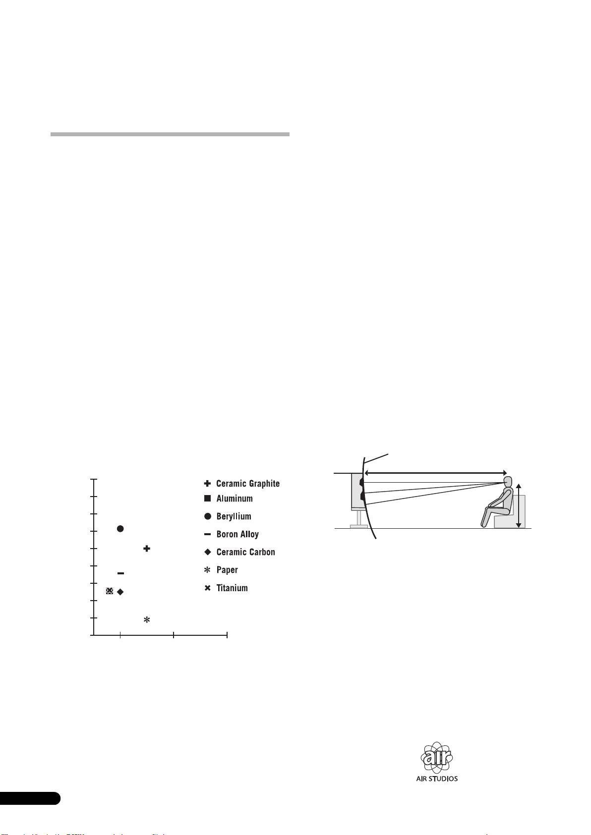
The CST’s tweeter features a ceramic graphite diaphragm that
(see illustration below). Made of up to 65 mm thick MDF (Medium
provides top-level strength and dampening characteristics that
Density Fiberboard), this baffle is, moreover, strong enough to
are practically unrivaled by any other available materials currently
contain the force of the drivers. Additionally, the bass port has
used in high-end audio speaker systems. Ceramic graphite’s
been carved out of an extremely thick block of MDF, resulting in
lightness and exceptional strength combine to create speakers
the reduction of wind noise for clear, deep bass.
whose diaphragm resonance can be pushed far beyond their
audible range.
Precision curve
Velocity (m/s)
3 m
18 000
16 000
1 m
14 000
12 000
10 000
Crossover Networks
8 000
The crossover networks use only the finest components. Air cored
6 000
coils, noninductive resistors, and film capacitors in the signal path
are all carefully chosen and optimized for the CST driver to provide
4 000
the greatest transparency to the signal. The bass drivers use
silicon steel plate core inductors that minimize distortion and loss
2 000
during energy transfer. All components are connected directly to
their respective wiring materials, instead of a printed circuit-
0
board, allowing for minimal loss and maximum performance.
0.005 0.015 0.025
Inner Loss
Collaboration with Air Studios
Since its establishment by George Martin in 1969, London,
Magnesium Alloy Diaphragm
England’s Air Studios has earned unequivocal respect from
The CST’s midrange features a magnesium alloy diaphragm
scores of artists who recognize it as the world’s premier recording
whose characteristic lightness and high inner loss provide
studio. The Air Studios seal that was awarded to the S-4EX
excellent transience and minimal coloration of midrange sounds.
indicates that these speakers are capable of producing the high-
quality sound demanded by the world’s top-class sound creators.
4
En
Installation and Placement
How to install
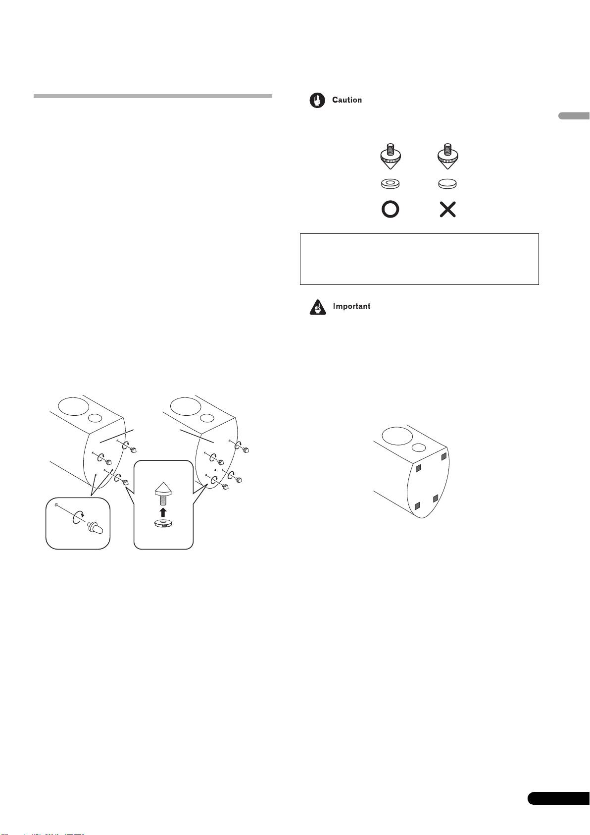
• Always use the spike bases as shown, with the indented
English
Please observe the following points when installing speakers:
surface facing up to receive the spike point.
These speakers are bookshelf-type speakers. They will provide best
performance when placed on a solid level surface away from the
floor. If placed directly on the floor, reverberation will be amplified,
producing a boomy, undefined sound. Ideally, the high-range
speakers (tweeters) should be placed at a height roughly the same
level as the listener’s ears. We recommend using the CP-4EX
speaker stand for optimum sound and stability. When using the
CP-4EX speaker stand, be sure to secure the speaker to the stand
with the provided screws to prevent the speaker from falling.
Installing the spikes
This speaker is provided with spikes and spike bases that should
be used to produce optimum sound quality.
Installation
1 Attach the spike nuts to the spikes.
2 Twist the spikes into the threaded metal inserts (M6)
embedded in the bottom of the speaker.
• As this unit weighs some 20 kg, it is very dangerous to try and
Consult the drawing and select either of the positions noted to fix
set the spike nut while tilting the speaker. Be sure to place the
the spikes.
unit on a soft area (such as a blanket) so that it does not
damage the floor, and carry out the installation with at least
two people.
When not using the spikes
To assure stable installation, affix the non-skid pads to the bottom
surface of each speaker.
3 Set the spike bases in the positions where the points of
the spikes will strike when the speaker is set down.
Place enough spike bases to match the number of spikes used.
4 Rotate the spikes to adjust their height, then rotate the
spike nuts counterclockwise to fix the spikes at the adjusted
height.
5 Set the speaker on the spike bases and adjust to be sure
the speaker is level and does not rock.
6 When mounting the spikes in three locations only.
a) Rotate the auxiliary feet to adjust their height.
Adjust the height so that about 1 mm to 2 mm of space
remains open between the feet and the installation surface.
b) Rotate the spike nuts counterclockwise to fix the
auxiliary feet at their adjusted height.
5
En
■ Attached in three positions ■ Attached in four positions
Attach the auxiliary feet
to prevent rocking.
Bottom of
speaker
Spike
Spike nut
Auxiliary feet
S-4EX_EN.book 5 ページ 2008年7月16日 水曜日 午後2時2分
If you do not use the spike bases when placing the
speakers, the spikes may cause damage to the floor. If
you plan on using the spikes we highly recommend to
use the spike bases.
S-4EX_EN.book 6 ページ 2008年7月16日 水曜日 午後2時2分
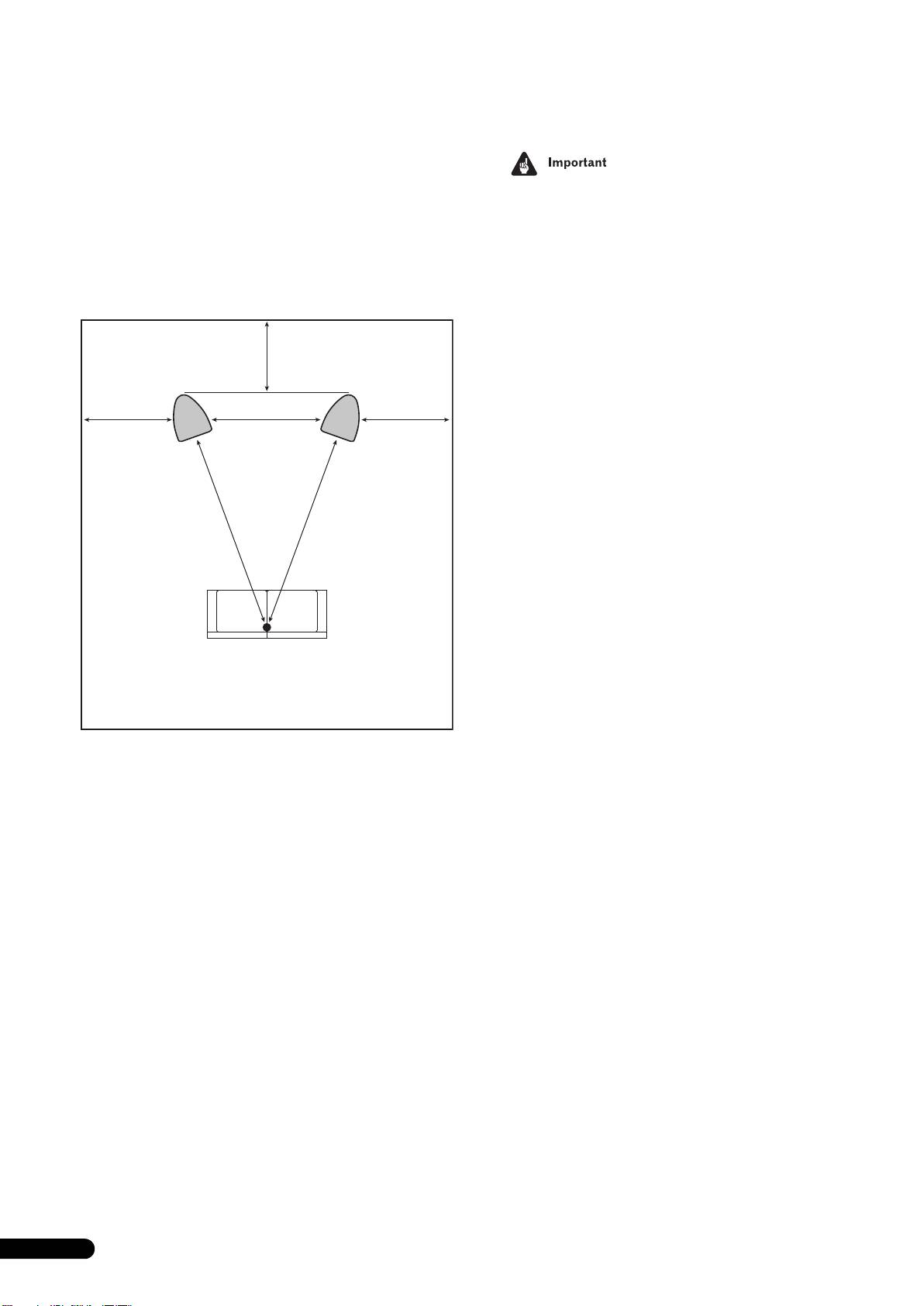
Choosing Where To Place The Speaker Systems
Placement within the listening room will have a great impact upon
the total performance of the S-4EX speaker system in terms of
• Do not place the speaker where it will be in direct sunlight, and
bass performance, tonal accuracy, and imaging. All rooms are
avoid positioning it near heaters and air conditioners. Doing
different and so this section is intended as a guide only.
so may cause warping and discoloration of the speaker
Experimentation in your room will yield optimum results.
cabinet and damage to the speaker.
Use the graphic below as a guide to determine optimal speaker
• Pioneer assumes no liability whatsoever for damages
placement.
resulting from assembly, improper mounting, insufficient
reinforcement, misuse of the product, acts of nature, etc.
.
30 cm to 60 cm
Speaker
Speaker
(left)
(right)
30 cm to 60 cm 30 cm to 60 cm
B
AA
Listening position
Distance “A” should be equal to or greater than distance “B.”
Each speaker should face the listening position.
6
En
Connections
Connecting to an amplifier
Connecting the cables
English
This speaker does not include speaker cables used for connecting
1 Switch off the power to your amplifier.
to an amplifier. Take the following factors into consideration when
2 Connect the speaker cables to the input terminals (lower)
choosing speaker cables so that you can get the most from your
on the back of the speaker. For input terminal polarity, red is
speaker system:
positive (+) and black is negative (–).
• Use heavy-gauge speaker cable if possible, and keep the
cables to the minimum necessary length.
3 Connect the other ends of the cables to the amp’s
speaker output terminals (for more details, refer to your amp
• If the length of cable required for left and right speakers
instruction manual).
differs, use cables of the same length, matched to the longer
distance.
• Cables have differing characteristics. Keep this in mind when
using any cable.
• Select cables with as little resistance as possible, and make
sure the cables to the speaker terminals and amp are firm and
secure.
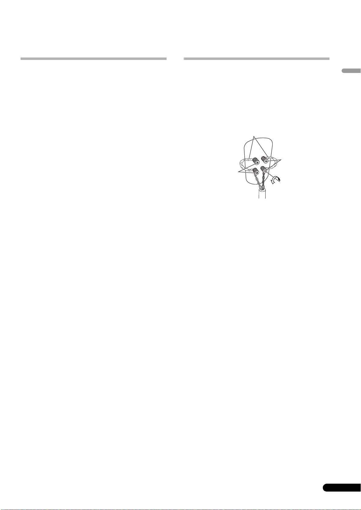
CAUTION
• Grasp the cap knobs on the lower input terminals and rotate
them to the left (counter-clockwise), insert the speaker cable
wires into the holes in the terminal posts, then tighten the
knobs to secure the short bar as well as the wires.
• You can also connect the speaker’s terminals with a banana
plug. When using a banana plug, be sure to remove the cap at
the tip of the input terminal.
• After connecting the plugs, pull lightly on the cables to make
sure that the ends of the cables are securely connected to the
terminals. Poor connections can create noise and
interruptions in the sound.
• If the cables’ wires happen to be pushed out of the terminals,
allowing the wires to come into contact with each other, it
places an excessive additional load on the amp. This may
cause the amp to stop functioning, and may even damage the
amp.
• When using a set of speakers connected to an amplifier, you
won’t be able to obtain the normal stereo effect if the polarity
of one of the speakers (left or right) is reversed.
7
En
T
S-4EX_EN.book 7 ページ 2008年7月16日 水曜日 午後2時2分
Short bar connectors
Red terminal
(+)
Black terminal
(–)
hese speaker terminals carry HAZARDOUS LIVE
voltage. To prevent the risk of electric shock when
connecting or disconnecting the speaker cables,
disconnect the power cord before touching any
uninsulated parts.
D3-4-2-2-3_A_En
S-4EX_EN.book 8 ページ 2008年7月16日 水曜日 午後2時2分
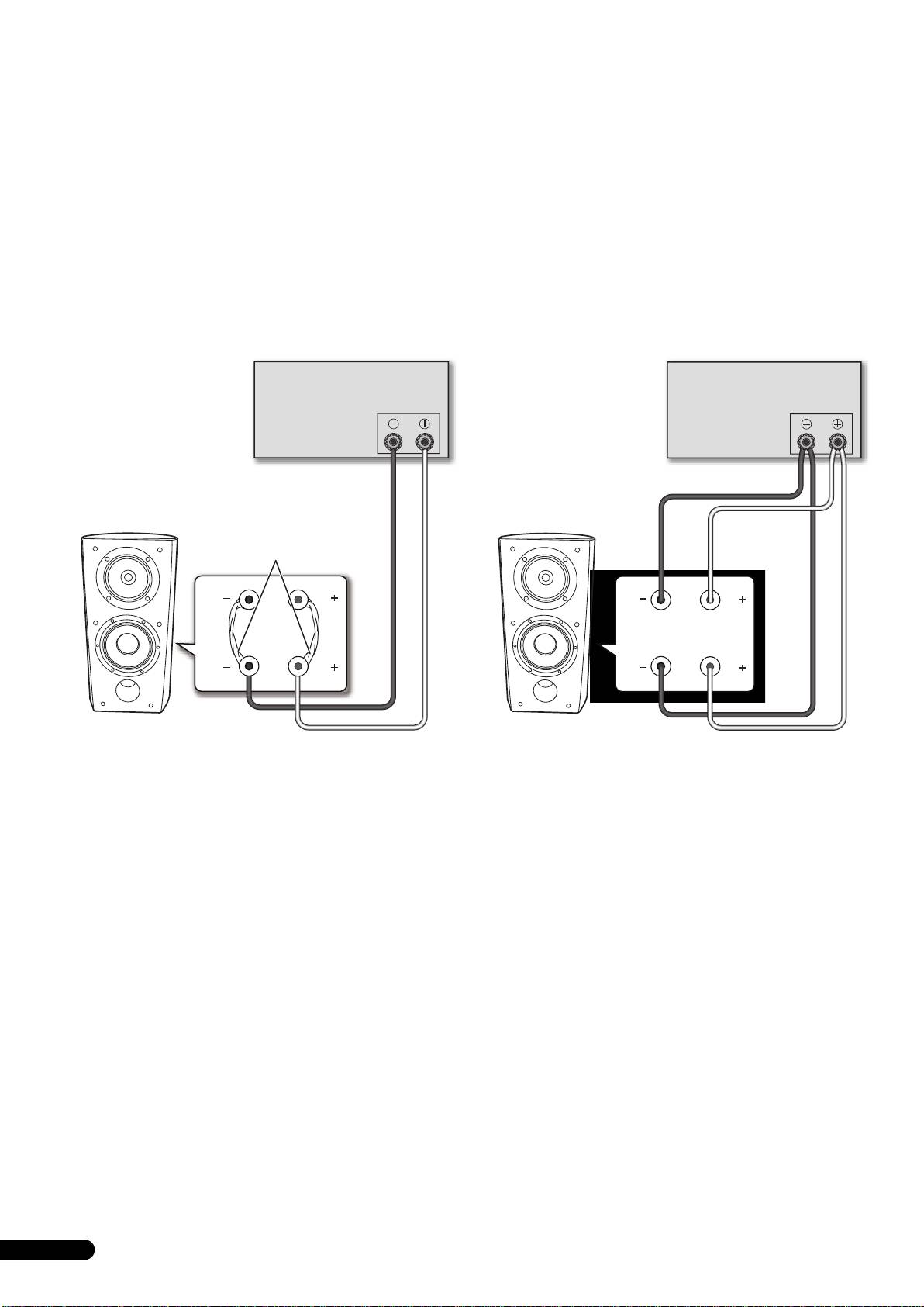
Single-Wire Connections
Bi-Wire Connections
For single-wire connections, connect the mid-to-high- and low-
In a bi-wiring connection, you independently plug in the speaker
frequency sections of the crossover network with the shorting link
systems running from the amp to their respective high- and low-
that was included with this unit, then connect the (+) wire from
frequency plugs. This results in the CST driver and bass drivers
your amplifier to either red binding post and the (–) wire from your
being independently connected directly to the amplifier, offering
amplifier to either black binding post, as shown in below.
you the freedom to optimize the cable type for each of the drivers.
Connect one set of wires to the bottom set of binding posts (bass
driver-specific network). Then connect a second set of wires to the
top binding posts (CST-specific network). Next, connect both sets
of wires to the appropriate terminals on your amplifier. Take care
to connect both (+) wires to the (+) amplifier terminals and both
(–) wires to the (–) amplifier terminals, as shown below.
Amplifier (rear)
Amplifier (rear)
SPEAKERS OUTPUT
SPEAKERS OUTPUT
(Only one channel shown)
(Only one channel shown)
Shorting link
connection
HF
HF
HF
HF
LF
LF
LF
LF
Speaker
Speaker
Speaker (rear): Input panel
Speaker (rear): Input panel
8
En
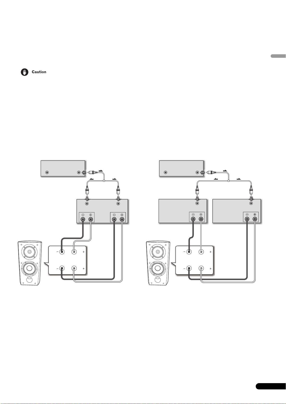
Bi-Amplification Connections
Bi-Amplification allows the best performance when using dedicated amplifiers for low- and mid-to-high-frequency sections.
There are two possible configurations, commonly referred to as horizontal and vertical bi-amping.
English
Remove the shorting links before connecting speaker cables in bi-amplifications connections.
Failure to do so may result in damage to your amplifiers.
Vertical Bi-Amping
Horizontal Bi-Amping
With this configuration, identical stereo amplifiers are used for
With this configuration, you may use different stereo amplifiers for
each speaker system. One channel of each amplifier drives the
the low- and mid-to-high-frequency sections of the speaker system
low frequency section and the other channel drives the high
(e.g., tube amplifiers for high frequency and solid state for low
frequency section, as shown below.
frequency). Each channel of one amplifier drives the low-
frequency section of each speaker system and each channel of
Connect one set of wires and amplifier channel to the bottom set
the other amplifier drives the mid-to-high-frequency section, as
of binding posts (bass driver-specific network).
shown below.
Then connect a second set of wires and the other amplifier
This method requires that both amplifiers have the same gain;
channel to the top binding posts (CST-specific network).
otherwise an imbalance will be heard between the low- and mid-
Take care to connect both (+) wires to the (+) amplifier terminals
to-high-frequency reproduction from the speaker system. If in
and both (–) wires to the (–) amplifier terminals.
doubt, please consult your local dealer.
9
En
Pre-amp (rear)
OUTPUT
OUTPUT
(Only one channel shown)
(Commercially-
available Y-adaptor)
Power amp
INPUT
INPUT
(rear)
SPEAKERS OUTPUT
Ch.1 Ch.2
HF
HF
LF
LF
Speaker (rear): Input panel
Speaker
S-4EX_EN.book 9 ページ 2008年7月16日 水曜日 午後2時2分
Pre-amp (rear)
OUTPUTOUTPUT
(Only one channel shown)
(Commercially-available
Y-adaptor)
Power amp (rear)
Power amp (rear)
(High frequency)
INPUT
(Low frequency)
INPUT
SPEAKERS OUTPUT
SPEAKERS OUTPUT
(Only one channel shown)
(Only one channel shown)
HF
HF
LF
LF
Speaker (rear): Input panel
Speaker
S-4EX_EN.book 10 ページ 2008年7月16日 水曜日 午後2時2分
Other Information
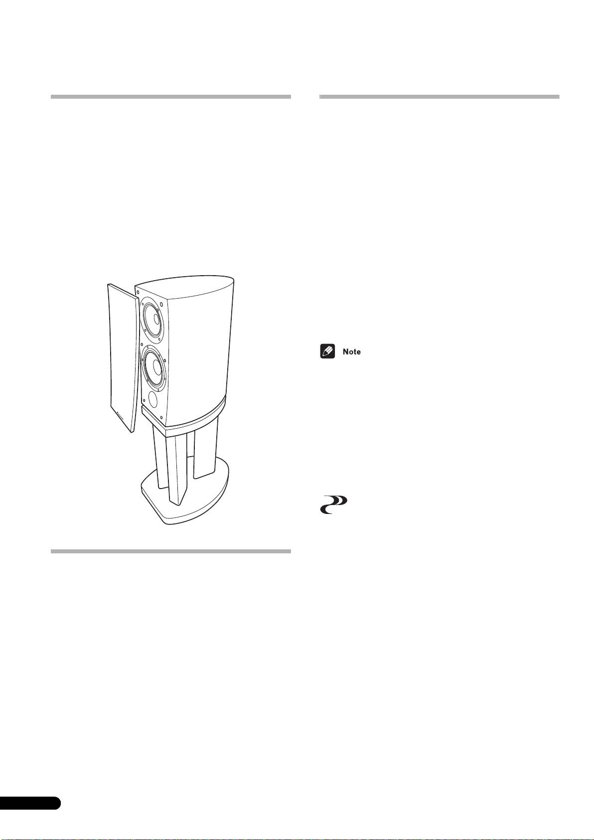
Attaching/Removing the Grille Cover
Specifications
This speaker system comes with grille covers which may be
Enclosure . . . . . . . . . . . . . . . . . . . . . . . . Bass-reflex floorstanding type
attached and removed by:
(magnetically shielded)
Configuration . . . . . . . . . . . . . . . . . . . . . . . . . . . . . . . . . . . . . . . . . . 3-way
1 To attach the grille cover, line up the holes on the speaker
5
Woofer. . . . . . . . . . . . . . . . . . . . . . . . . . . . . . 16 cm (6
/16 inch) cone x2
with the inserts on the grill, and press firmly.
1
3
Mid tweeter . . . . . . . . .14 cm (5
/2 inch) cone/3 cm (1
/16 inch) dome
Impedance . . . . . . . . . . . . . . . . . . . . . . . . . . . . . . . . . . . . . . . . . . . . . 6 Ω
2 To remove the grille cover, grab it by its bottom with
Frequency response. . . . . . . . . . . . . . . . . . . . . . . . . . . .34 Hz to 100 kHz
both hands and gently pull toward you to separate the
Sensitivity . . . . . . . . . . . . . . . . . . . . . . . . . . . . . . . . . . . . 85.5 dB (2.83 V)
bottom part of the grille from the speaker.
Maximum input power. . . . . . . . . . . . . . . . . . . . . . . . . . . . . . . . . . 160 W
3 Slide your hands up to the middle section of the grille,
Exterior dimensions . . . . . . . 263 (W) mm x 490 (H) mm x 387 (D) mm
and once again pull gently toward you. This will remove the
3
5
1
10
/8 (W) in. x 19
/16 (H) in. x 15
/4 (D) in.
middle section of the grille from the speaker.
Weight . . . . . . . . . . . . . . . . . . . . . . . . . . . . . . . . . . . . . 20 kg (44 lbs 2 oz.)
4 Finally, repeat this same motion for the top part of the
Supplied accessories
grille, removing the grille entirely from the speaker.
Spikes (with attached nuts). . . . . . . . . . . . . . . . . . . . . . . . . . . . . . . . . . .4
Spike bases. . . . . . . . . . . . . . . . . . . . . . . . . . . . . . . . . . . . . . . . . . . . . . . .4
Auxiliary feet . . . . . . . . . . . . . . . . . . . . . . . . . . . . . . . . . . . . . . . . . . . . . . .2
Non-skid pads. . . . . . . . . . . . . . . . . . . . . . . . . . . . . . . . . . . . . . . . . . . . . .4
Grille . . . . . . . . . . . . . . . . . . . . . . . . . . . . . . . . . . . . . . . . . . . . . . . . . . . . .1
Operating instructions
Specifications and design subject to possible modification
without notice, due to improvements.
Magnetic shielding
This speaker system is magnetically shielded. However,
depending on the installation location, color distortion may occur
if the speaker system is installed extremely close to the screen of
a television set.
If this happens, turn off the television, then turn it on again after
15 min to 30 min. If the problem persists, place the speaker system
away from the television set.
is a trademark placed on a product with Pioneer’s Phase
Control technology. This technology enables high-grade sound
reproduction through each component by improving overall
phase matching.
Cleaning the speaker cabinet
With normal use, wiping with a dry cloth should be sufficient to
keep the cabinet clean. If necessary, clean with a cloth dipped in
a neutral cleanser diluted five or six times with water, and wrung
out well. Do not use furniture wax or cleansers.
Published by Pioneer Corporation.
Never use thinners, benzine, insecticide sprays or other chemicals
Copyright © 2008 Pioneer Corporation.
on or near this unit since these will corrode the surfaces.
All rights reserved.
10
En
S-4EX_EN.book 11 ページ 2008年7月16日 水曜日 午後2時2分
English
AFTER-SALES SERVICE FOR PIONEER PRODUCTS
Please contact the dealer or distributor from where you purchased the
product for its after-sales service (including warranty conditions) or any
other information. In case the necessary information is not available,
please contact the Pioneer’s subsidiaries (regional service headquarters)
listed below:
PLEASE DO NOT SHIP YOUR PRODUCT TO THE COMPANIES at the
addresses listed below for repair without advance contact, for these
companies are not repair locations.
AMERICA
PIONEER ELECTRONICS SERVICE, INC.
P.O. BOX 1760, LONG BEACH, CA 90801-1760, U.S.A.
CUSTOMER SERVICE HOTLINE : 1 (800) 421-1404
EUROPE
PIONEER EUROPE NV
EUROPEAN SERVICE DIVISION
HAVEN 1087, KEETBERGLAAN 1, B-9120 MELSELE, BELGIUM
ASEAN
PIONEER ELECTRONICS ASIACENTRE PTE. LTD.
SERVICE DEPARTMENT
253, ALEXANDRA ROAD #04-01 SINGAPORE 159936
JAPAN AND OTHERS
PIONEER CORPORATION (HEAD OFFICE)
CUSTOMER SUPPORT CENTER
4-1, MEGURO 1-CHOME, MEGURO-KU, TOKYO 153-8654 JAPAN
S016_A_En
11
En
