Pioneer GM-6400F: инструкция
Раздел: Музыкальное Оборудование
Тип: Усилитель Мощности
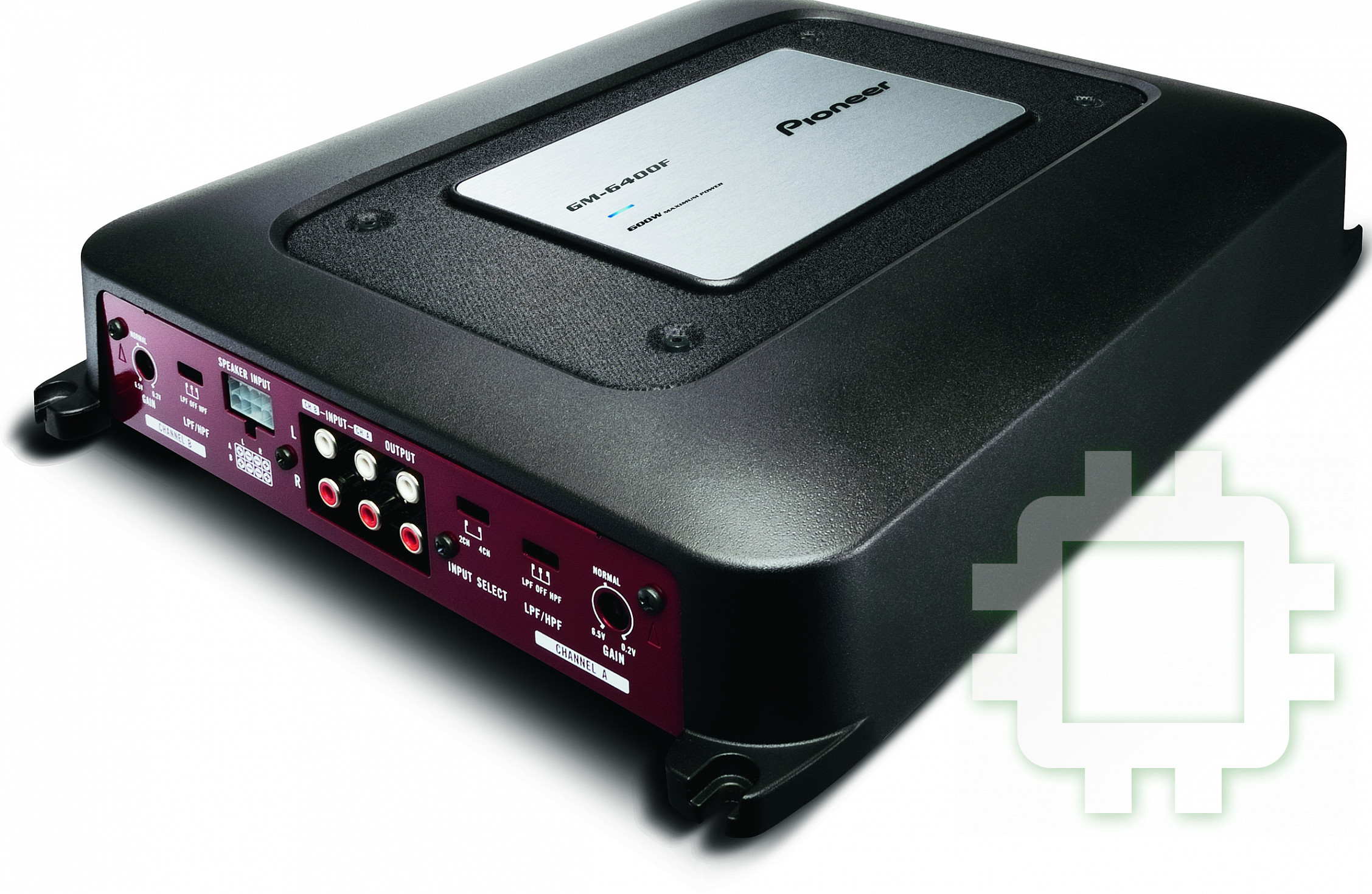
Инструкция к Усилителю Мощности Pioneer GM-6400F

English Español Deutsch Français Italiano Nederlands
BRIDGEABLE FOUR-CHANNEL POWER AMPLIFIER
AMPLIFICADOR DE POTENCIA DE CUATRO CANALES DE PUENTE
UBERBRUCKBARER 4-KANAL-LEISTUNGSVERSTARKER
AMPLIFICATEUR DE PUISSANCE PONTABLE A QUATRE CANAUX
AMPLIFICATORE DI POTENZA QUADRICANALE COLLEGABILE A PONTE
BRUGSCHAKELBARE VIERKANAALS EINDVERSTERKER
ЧЕТЫРЕХКАНАЛЬНЫЙ УСИЛИТЕЛЬ МОЩНОСТИ МОСТОВОЙ СХЕМЫ
GM-6400F
Owner’s Manual
Manual de instrucciones
Bedienungsanleitung
Mode d’emploi
Manuale d’istruzioni
Русский
Handleiding
Руководство пользователя
CZR5555Acover.indd1CZR5555Acover.indd1 2008/08/0711:21:352008/08/0711:21:35

Contents
Thank you for purchasing this PIONEER product.
Please read through this manual before using the product for the first time, to en-
sure proper use. After reading, please keep the manual in a safe and accessible place
for future r eference.
Before you start
Visit our website 3
In case of trouble 3
Before connecting/installing the amplifier 3
Setting the Unit
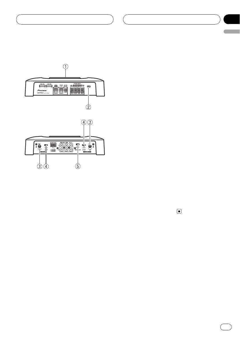
What’s what 5
Setting gain properly 5
Connecting the units
Connection diagram 7
Before connecting the amplifier 7
About bridged mode 8
About suitable specification of speaker 8
Connecting the speakers 8
Connections when using the RCA input
jack 10
Connections when using the speaker input
wire 10
Connecting the power terminal 11
Connecting the speaker output
terminals 12
Installation
Before installing the amplifier 13
Example of installation on the floor mat or
chassis 13
Additional information
Specifications 14
2
En
Section
Before you start
01
English
In case of trouble
Should this product fail to operate properly,
contact your dealer or nearest authorized
Pioneer Service Station.
If you want to dispose this product, do not mix
it with general household waste. There is a se-
parate collection system for used electronic
Before connecting/
products in accordance with legislation that re-
installing the amplifier
quires proper treatment, recovery and recy-
cling.
WARNING
! The use of a special red battery and ground
Private households in the member states of
wire RD-223, available separately, is recom-
the EU, in Switzerland and Norway may return
mended. Connect the battery wire directly to
their used electronic products free of charge
the car battery positive terminal + and the
to designated collection facilities or to a retai-
ground wire to the car body.
ler (if you purchase a similar new one).
! This unit is for vehicles with a 12 V battery and
For countries not mentioned above, please
negative grounding. Before installing in re-
contact your local authorities for the correct
creational vehicles, trucks or buses, check the
method of disposal.
battery voltage.
By doing so you will ensure that your disposed
! Always use a fuse of the rating prescribed.
product undergoes the necessary treatment,
The use of an improper fuse could result in
recovery and recycling and thus prevent po-
overheating and smoke, damage to the pro-
tential negative effects on the environment
duct and injury, including burns.
and human health.
! Check the connections of the power supply
and speakers if the fuse of the separately sold
battery wire or the amplifier fuse blows. Deter-
mine and resolve the cause, then replace the
fuse with identical equivalent.
Visit our website
! Do not allow this unit to come into contact
Visit us at the following site:
with liquids. Electrical shock could result.
http://www.pioneer.co.uk
Also, damage to this unit, smoke, and over-
! Register your product. We will keep the de-
heating could result from contact with liquids.
tails of your purchase on file to help you
The surfaces of the amplifier and any attached
refer to this information in the event of an
speakers may also heat up and cause minor
insurance claim such as loss or theft.
burns.
! We offer the latest information about
! In the event of any abnormality, the power
Pioneer Corporation on our website.
supply to the amplifier is cut off to prevent
equipment malfunction. If this occurs, switch
the system power OFF and check the power
supply and speaker connections. If you are un-
able to determine the cause, please contact
your dealer.
3
En

Section
01
Before you start
! Always disconnect the negative * terminal of
the battery beforehand to avoid the risk of
electric shock or short circuit during installa-
tion.
CAUTION
! Always keep the volume low enough so that
you can hear sounds from outside the vehicle.
! Extended use of the car stereo while the en-
gine is at rest or idling may exhaust the
battery.
4
En
Section
Setting the Unit
02
English
! If using only one input plug, set the gain
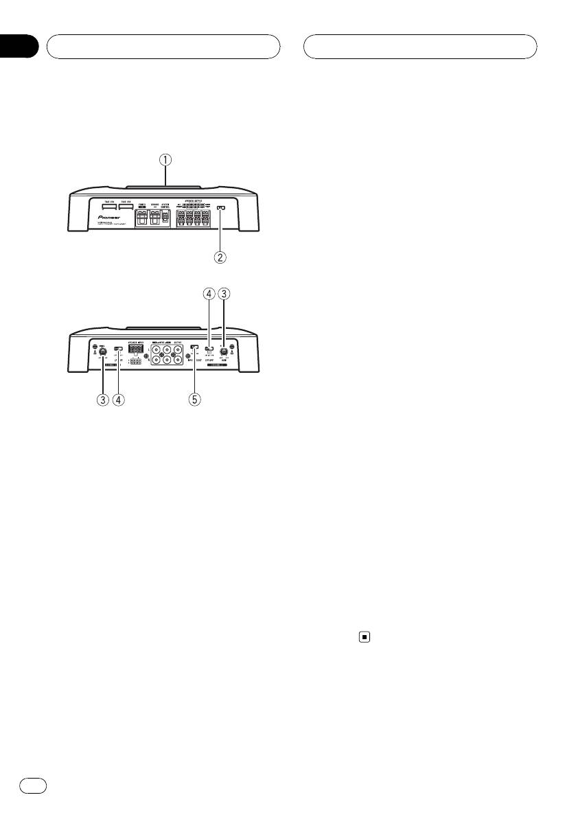
What’s what
controls for speaker outputs A and B to
Front side
the same position.
! For use with an RCA equipped car stereo
(standard output of 500 mV), set to the
NORMAL position. For use with an RCA
equipped Pioneer car stereo, with max.
output of 4 V or more, adjust level to
match that of the car stereo output.
4 LPF (low-pass filter)/HPF (high-pass fil-
Rear side
ter) select switch
Switch the settings based on the connected
speaker.
! When the Subwoofer is connected:
Select LPF. This eliminates high range
frequency and outputs low range fre-
quency.
! When the full range speaker is con-
nected:
Select HPF or OFF. HPF eliminates low
To adjust the switch, use a flathead screwdri-
range frequency and output high range
ver if needed.
frequency. OFF outputs the entire fre-
quency range.
1 Power indicator
The power indicator lights up to indicate
5 INPUT SELECT (input select) switch
power ON.
Select 2CH for two-channel input and 4CH
for four–channel input.
2 BFC (beat frequency control) switch
Located front side the unit. If beats are audi-
ble while listening to MW/LW broadcasts via
car stereo, change the BFC switch using a
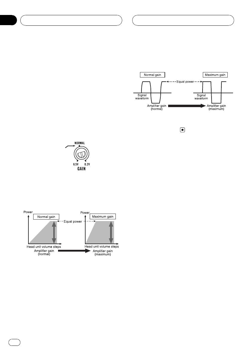
Setting gain properly
small flathead screwdriver.
! Protective function included to prevent
malfunction of the unit and/or speakers
3 GAIN (gain) control
due to excessive output, improper use or
Adjusting gain controls CHANNEL A (chan-
improper connection.
nel A) and CHANNEL B (channel B) helps
! When outputting high volume sound etc.,
align the car stereo output to the Pioneer
this function cuts off the output for a few
amplifier. Default setting is the NORMAL
seconds as a normal function, but output
position.
is restored when the volume of the head
If output remains low, even when the car
unit is turned down.
stereo volume is turned up, turn controls to
lower level. If distortion occurs when the car
stereo volume is turned up, turn these con-
trols to higher level.
5
En
Section
02
Setting the Unit
! A cut in sound output may indicate impro-
Signal waveform when outputting at
per setting of the gain control. To ensure
high volume using amplifier gain
continuous sound output with the head
control
unit at a high volume, set amplifier gain
control to a level appropriate for the preout
maximum output level of the head unit, so
that volume can remain unchanged and to
control excess output.
! Despite correct volume and gain settings,
the unit sound still cuts out periodically. In
such cases, please contact the nearest
Signal waveform distorted with high output, if
authorized Pioneer Service Station.
you raise the gain of the amplifier the power
changes only slightly.
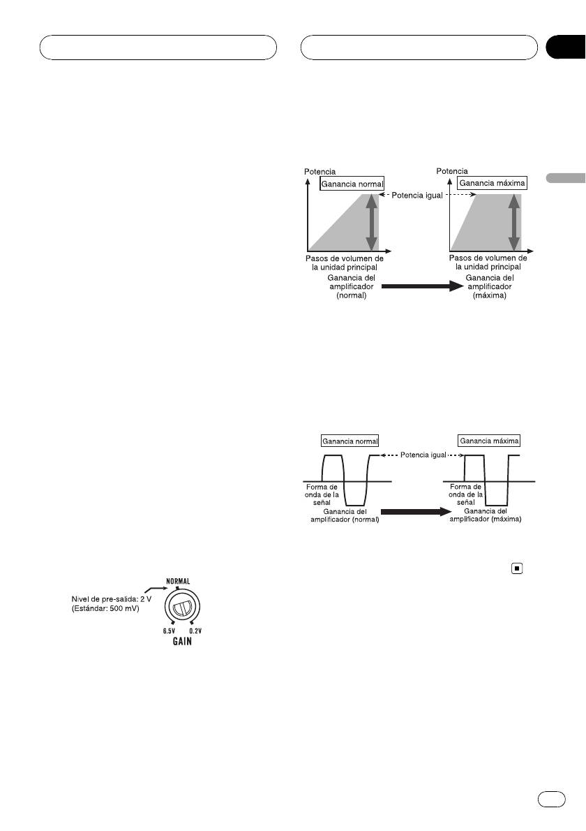
Gain control of this unit
Preout level: 2 V
(Standard: 500mV)
Above illustration shows NORMAL gain set-
ting.
Relationship between amplifier gain
and head unit output power
If amplifier gain is raised improperly, this will
simply increase distortion, with little increase
in power.
6
En
Section
Connecting the units
03
English
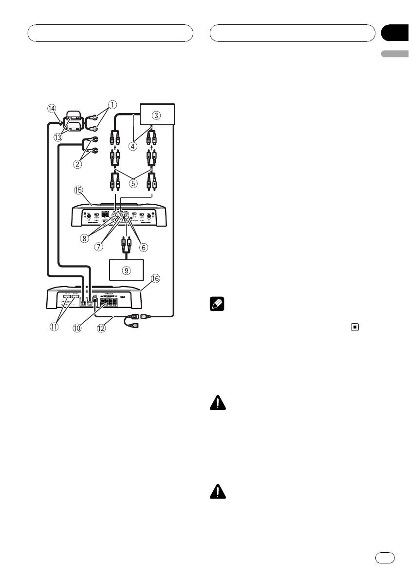
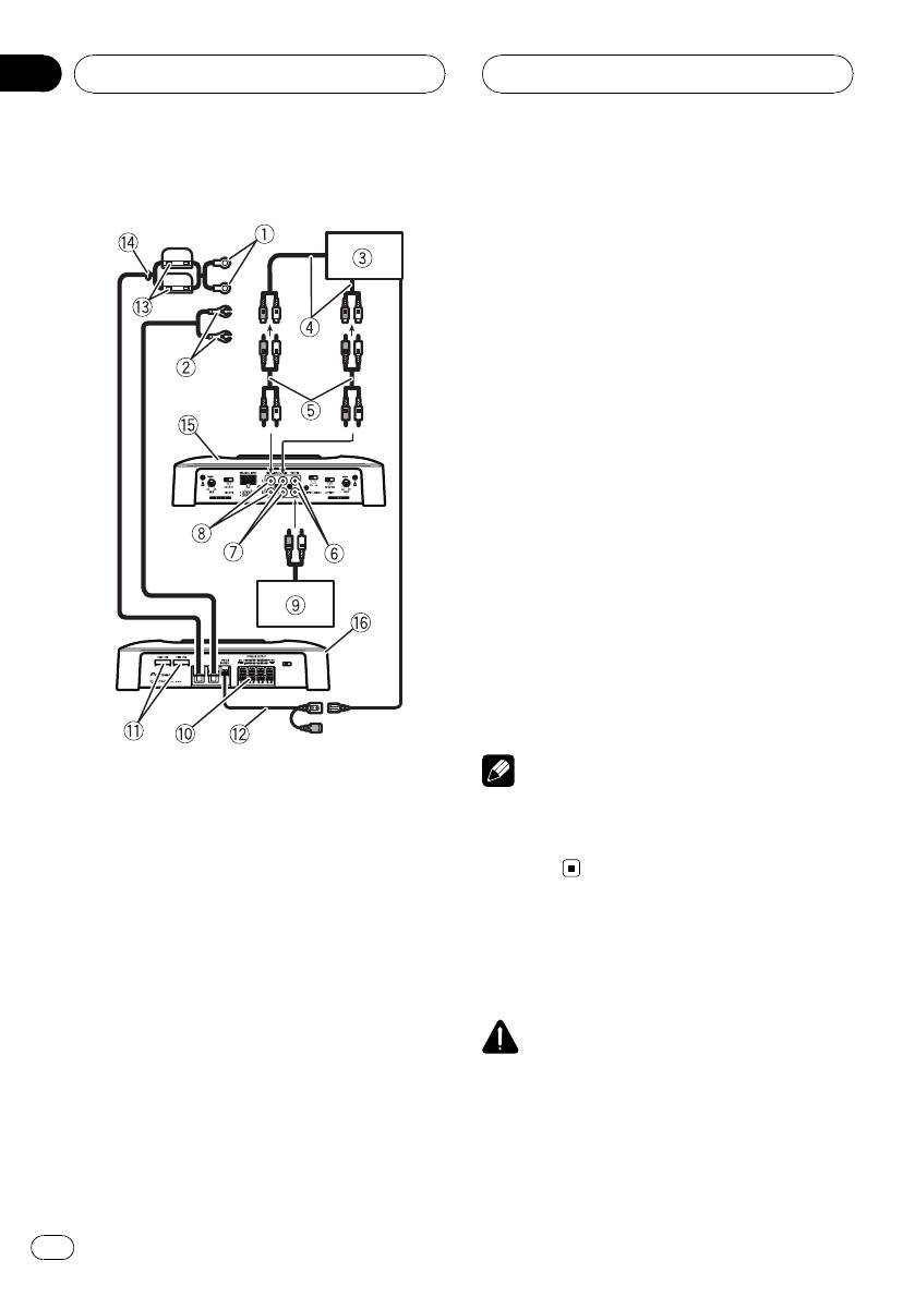
9 Amplifier with RCA input jacks (sold sepa-
Connection diagram
rately)
a Speaker output terminals
Please see the following section for speaker
connection instructions. Refer to Connections
when using the speaker input wire on page 10.
b Fuse (25 A) × 2
c System remote control wire (sold separately)
Connect male terminal of this wire to the sys-
tem remote control terminal of the car stereo
(SYSTEM REMOTE CONTROL). The female
terminal can be connected to the auto-anten-
na relay control terminal. If the car stereo
lacks a system remote control terminal, con-
nect the male terminal to the power terminal
via the ignition switch.
d Fuse (30 A) × 2
e Grommet
f Rear side
g Front side
Note
INPUT SELECT (input select) switch must be set.
For details, see Setting the Unit on page 5.
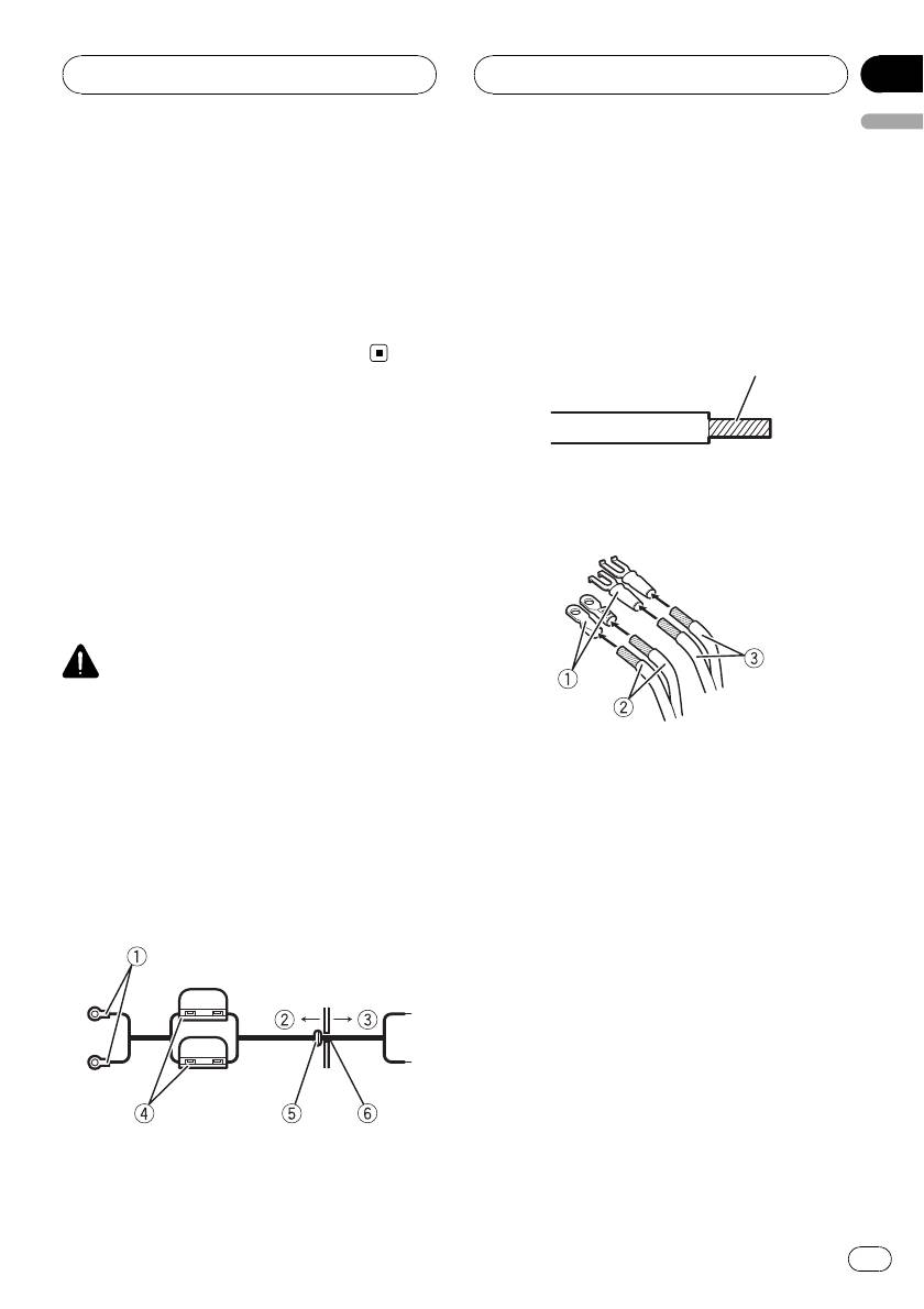
1 Special red battery wire
RD-223 (sold separately)
After completing all other amplifier connec-
Before connecting the
tions, finally connect the battery wire terminal
of the amplifier to the positive (+) battery
amplifier
terminal.
2 Ground wire (Black)
WARNING
RD-223 (sold separately)
! Secure the wiring with cable clamps or adhe-
Connect to metal body or chassis.
sive tape. To protect the wiring, wrap sections
3 Car stereo with RCA output jacks (sold sepa-
in contact with metal parts in adhesive tape.
rately)
! Never cut the insulation of the power supply
4 External output
to feed power to other equipment. Current ca-
If only one input plug is used, do not connect
pacity of the wire is limited.
anything to RCA input jack B.
5 Connecting wire with RCA pin plugs (sold se-
parately)
CAUTION
! Never shorten any wires, the protection circuit
6 RCA output jack
may malfunction.
7 RCA input jack A
8 RCA input jack B
7
En
Section
03
Connecting the units
! Never ground speaker wire directly or band to-
About suitable
gether multiple speakers’ negative (*) lead
specification of speaker
wires.
! If the system remote control wire of the ampli-
Ensure speakers conform to the following
fier is connected to the power terminal via the
standards, otherwise there is a risk of fire,
ignition switch (12 V DC), the amplifier will re-
smoke or damage. Speaker impedance is 2 W
main on with the ignition whether the car
to 8 W,or4W to 8 W for two-channel and other
stereo is on or off, which may exhaust battery
bridge connections.
if the engine is at rest or idling.
! Install and route the separately sold battery
Subwoofer
wire as far as possible from the speaker wires.
Speaker channel Power
Install and route the separately sold battery
wire, ground wire, speaker wires and the am-
Nominal input:
Four-channel output
plifier as far away as possible from the anten-
Min. 70 W
na, antenna cable and tuner.
Nominal input:
Two-channel output
Min. 200 W
Three-channel
Nominal input:
Speaker output A
Min. 70 W
About bridged mode
Three-channel
Nominal input:
Speaker output B
Min. 200 W
Other than subwoofer
Speaker channel Power
Max. input:
Four-channel output
Min. 120 W
Max. input:
Two-channel output
Min. 300 W
Three-channel
Max. input:
Speaker output A
Min. 120 W
Speaker impedance is max. 4 W, please carefully
Three-channel
Max. input:
check. Improper connection to the amplifier may
Speaker output B
Min. 300 W
result in malfunction or personal injury due to
burns from overheating.
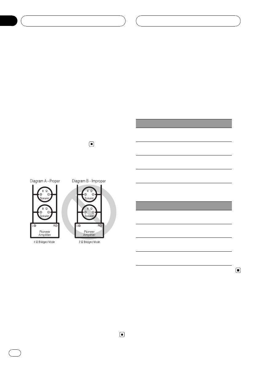
For bridged mode for a two-channel amplifier,
with a 4 W load, either wire two 8 W speakers in
parallel, Left + and Right * (Diagram A) or use a
single 4 W speaker. For other amplifiers, please
Connecting the speakers
follow the speaker output connection diagram for
The speaker output mode can be four-channel,
bridging shown on rear: two 8 W speakers in par-
three-channel (stereo + mono) or two-channel
allel for a 4 W load or a single 4 W speaker per
(stereo, mono). Connect the speaker leads
channel.
based on the mode and the figures shown
For any further enquiries, contact your local
below.
authorized Pioneer dealer or customer service.
8
En
Section
Connecting the units
03
English
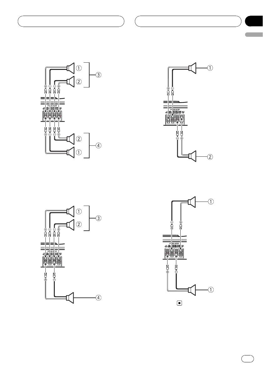
Four-channel output
Two-channel output (Stereo)
1 Right
1 Speaker (Right)
2 Left
2 Speaker (Left)
3 Speaker out A
4 Speaker out B
Two-channel output (Mono)
Three-channel output
1 Speaker (Mono)
1 Right
2 Left
3 Speaker out A
4 Speaker out B (Mono)
9
En
Section
03
Connecting the units
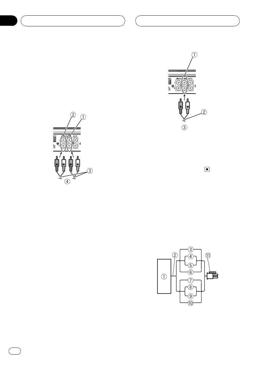
Connections when using
the RCA input jack
Connect the car stereo RCA output jack and
the RCA input jack of the amplifier.
Four-channel / Three-channel output
! Slide INPUT SELECT (input select) switch
to 4CH position.
1 RCA input jack A
For two-channel output, connect the RCA
plugs to the RCA input jack A.
2 Connecting wire with RCA pin plugs (sold se-
parately)
3 From car stereo (RCA output)
1 RCA input jack A
2 RCA input jack B
Connections when using
3 Connecting wires with RCA plugs (sold sepa-
the speaker input wire
rately)
Connect the car stereo speaker output wires
4 From car stereo (RCA output)
to the amplifier using the supplied speaker
If only one input plug is used, e.g. when the
input wire.
car stereo has only one output (RCA output),
! Do not connect both the RCA input and the
connect the plug to RCA input jack A rather
speaker input at the same time.
than B.
Two-channel output (Stereo) / (Mono)
! Slide INPUT SELECT (input select) switch
to 2CH position.
1 Car Stereo
2 Speaker output
3 White: CH A, Left +
4 White/black: CH A, Left *
10
En
Section
Connecting the units
03
English
5 Gray/black: CH A, Right *
4 Fuse (30 A) × 2
6 Gray: CH A, Right +
5 Insert the O-ring rubber grommet into the
7 Violet: CH B, Right +
vehicle body.
8 Violet/black: CH B, Right *
6 Drill a 14 mm hole into the vehicle body.
9 Green/black: CH B, Left *
a Green: CH B, Left +
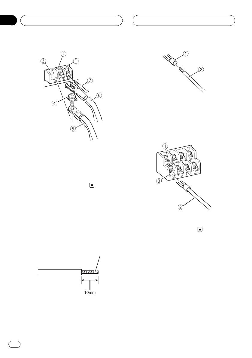
2 Twist the battery wire, ground wire
b Speaker input connector
and system remote control wire.
To speaker input terminal of this unit.
Twist
Connecting the power
terminal
3 Attach lugs to wire ends. Lugs not sup-
plied.
! The use of a special red battery and ground
Use pliers, etc., to crimp lugs to wires.
wire RD-223, available separately, is recom-
mended. Connect the battery wire directly
to the car battery positive terminal (+) and
the ground wire to the car body.
WARNING
If the battery wire is not securely fixed to the term-
inal using the terminal screws, there is a risk of
overheating, malfunction and injury, including
1 Lug
minor burns.
2 Battery wire
3 Ground wire
1 Route battery wire from engine com-
partment to the vehicle interior.
4 Connect the wires to the terminal.
After completing all other amplifier connec-
Fix the wires securely with the terminal
tions, finally connect the battery wire terminal
screws.
of the amplifier to the positive (+) battery
terminal.
1 Positive (+) terminal
2 Engine compartment
3 Vehicle interior
11
En
Section
03
Connecting the units
1 Lug
2 Speaker wire
3 Connect the speaker wires to the
speaker output terminals.
Fix the speaker wires securely with the term-
inal screws.
1 System remote control terminal
2 GND terminal
3 Power terminal
4 Terminal screws
5 Battery wire
6 Ground wire
7 System remote control wire
Connecting the speaker
1 Terminal screws
output terminals
2 Speaker wires
1 Expose the end of the speaker wires
3 Speaker output terminals
using nippers or a cutter by about 10 mm
and twist.
Twist
2 Attach lugs to speaker wire ends. Lugs
not supplied.
Use pliers, etc., to crimp lugs to wires.
12
En
Section
Installation
04
English
! After installing the amplifier, confirm that the
Before installing the amplifier
spare tire, jack and tools can be easily re-
moved.
WARNING
! To ensure proper installation, use the supplied
parts in the manner specified. If any parts
other than those supplied are used, they may
damage internal parts of the amplifier, or be-
Example of installation on
come loose causing the amplifier to shut
the floor mat or chassis
down.
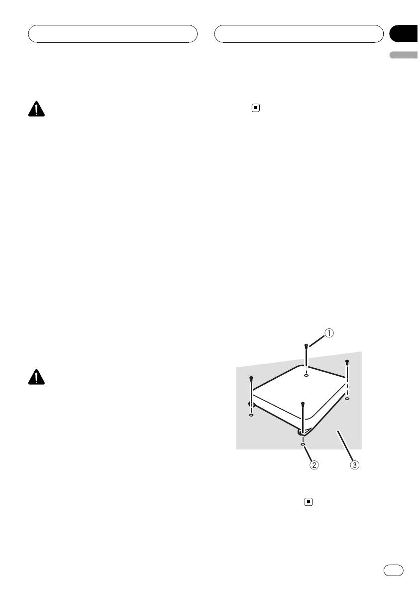
1 Place the amplifier in the desired instal-
! Do not install in:
lation location.
— Places where it could injure the driver or
Insert the supplied tapping screws (4 mm ×
passengers if the vehicle stops suddenly.
18 mm) into the screw holes and push on the
— Places where it may interfere with the dri-
screws with a screwdriver so they make an im-
ver, such as on the floor in front of the dri-
print where the installation holes are to be lo-
ver’s seat.
cated.
! Install tapping screws in such a way that the
screw tip does not touch any wire. This is im-
2 Drill 2.5 mm diameter holes at the im-
portant to prevent wires from being cut by vi-
prints either on the carpet or directly on
bration of the car, which can result in fire.
the chassis.
! Make sure that wires are not caught in the
sliding mechanism of the seats, resulting in a
3 Install the amplifier with the use of
short-circuit.
supplied tapping screws (4 mm × 18 mm).
! When drilling to install the amplifier, always
confirm no parts are behind the panel and
protect all cables and important equipment
(e.g. fuel/brake lines, wiring) from damage.
CAUTION
! To ensure proper heat dissipation of the ampli-
fier, ensure the following during installation:
— Allow adequate space above the amplifier
for proper ventilation.
— Do not cover the amplifier with a floor mat
or carpet.
! Avoid routing wires through hot areas, such
as near the heater outlet. Heat may damage
the insulation, resulting in a short-circuit
1 Tapping-screws (4 mm × 18 mm)
through the vehicle body.
2 Drill a 2.5 mm diameter hole
! The optimal installation location differs de-
3 Floor mat or chassis
pending on the car model. Secure the ampli-
fier at a sufficiently rigid location.
! Firstly make temporary connections and
check to ensure the amplifier and system op-
erate properly.
13
En

Appendix
Additional information
working out total current drawn by multiple
Specifications
power amplifiers.
Power source ............................. 14.4 V DC (10.8 V to 15.1 V
allowable)
Grounding system ................... Negative type
Current consumption ............ 35 A (at continuous power,
4 W )
Average current drawn ......... 9 A (4 W for four chan nels)
15 A (4 W for two channels)
Fuse ................................................ 25 A × 2
Dimensions (W × H × D) ... 265 mm × 62 mm × 346
mm
Weight .......................................... 3.8 kg (Leads for wiri ng not
included)
Maximum power output ....... 120 W × 4 (4 W)/300W×2
(4 W)
Continuous power output ... 60 W × 4 (at 14.4 V, 4 W,20
Hz to 20 kHz 0.2% THD)
150 W × 2 (at 14.4 V, 4 W,20
Hz to 20 kHz 0.8% THD)
75 W × 4 (at 14.4 V, 2 W,20
Hz to 20 kHz 0.8% THD)
Load impedance ...................... 4 W (2 W to 8 W allowable)
(Bridge connection: 4 W to 8
W allowable)
Frequency response ............... 10 Hz to 50 kHz (+0 dB, –1
dB)
Signal-to-noise ratio ............... 95 dB (IEC-A network)
Distortion ..................................... 0.03 % (10 W, 1 kHz)
Separation .................................. 70 dB (1 kHz)
Low pass filter:
Cut off frequency ........... 80 Hz
Cut off slope ..................... –12 dB/oct
High pass filter:
Cut off frequency ........... 80 Hz
Cut off slope ..................... –12 dB/oct
Gain control:
RCA ...................................... 200 mV to 6.5 V
Speaker .............................. 0.8 V to 26 V
Maximum input level / impedance:
RCA ...................................... 6.5 V / 22 kW
Speaker .............................. 26 V / 90 kW
Notes
! Specifications and the design are subject to
modifications without notice due to improve-
ments.
! The average current drawn is nearly the maxi-
mum current drawn by this unit when an
audio signal is input. Use this value when
14
En

Contenido
Gracias por haber comprado este producto PIONEER.
Lea con detenimiento este manual antes de utilizar el producto por primera vez,
para que pueda darle el mejor uso posible. Una vez leído, guarde este manual en un
lugar seguro y a mano para consultarlo en el futuro.
Español
Antes de comenzar
Visite nuestro sitio Web 16
En caso de problemas 16
Antes de conectar/instalar el
amplificador 16
Configuración de la unidad
Qué es cada cosa 18
Configuración correcta de la ganancia 19
Conexión de las unidades
Diagrama de conexión 20
Antes de conectar el amplificador 20
Acerca del modo en puente 21
Acerca de una especificación adecuada del
altavoz 21
Conexión de altavoces 22
Conexiones al utilizar una toma de entrada
RCA 23
Conexiones al utilizar el cable de entrada del
altavoz 23
Conexión del terminal de potencia 24
Conexión de los terminales de salida del
altavoz 25
Instalación
Antes de instalar el amplificador 27
Ejemplo de instalación en la alfombra o
chasis 27
Información adicional
Especificaciones 29
15
Es
Sección
01
Antes de comenzar
En caso de problemas
Si este producto no funciona correctamente,
contacte con su distribuidor o con el servicio
técnico oficial Pioneer más próximo a su
domicilio.
Si desea deshacerse de este producto, no lo
mezcle con los residuos generales de su
hogar. De conformidad con la legislación vi-
gente, existe un sistema de recogida distinto
Antes de conectar/instalar
para los productos electrónicos que requieren
el amplificador
un procedimiento adecuado de tratamiento,
recuperación y reciclado.
ADVERTENCIA
! Se recomienda el uso del cable de batería rojo
Las viviendas privadas en los estados miem-
especial y el de toma a tierra RD-223, disponi-
bros de la UE, en Suiza y Noruega pueden de-
bles por separado. Conecte el cable de batería
volver gratuitamente sus productos
directamente al terminal positivo + de la ba-
electrónicos usados en los centros de recolec-
tería del automóvil y el cable de puesta a tierra
ción previstos o bien en una tienda minorista
a la carrocería del automóvil.
(si adquieren un producto similar nuevo).
! Esta unidad está pensada para vehículos con
En el caso de los países que no se han men-
una batería de 12 voltios y una conexión a tie-
cionado en el párrafo anterior, póngase en
rra negativa. Antes de instalar en un vehículo
contacto con las autoridades locales a fin de
recreacional, camión o autobús, compruebe
conocer el método de eliminación correcto.
el voltaje de la batería.
Al actuar siguiendo estas instrucciones, se
! Utilice siempre un fusible con la tensión no-
asegurará de que el producto eliminado se so-
minal indicada. El uso de un fusible inadecua-
meta a los procesos de tratamiento, recupera-
do podría provocar sobrecalentamiento y
ción y reciclaje necesarios, evitando de este
humo, daños en el producto y lesiones, e in-
modo efectos potencialmente negati vos en el
cluso quemaduras.
entorno y la salud humana.
! Compruebe las conexiones de la fuente de ali-
mentación y los altavoces si se funde el fusi-
ble del cable de la batería vendido por
separado o el fusible del amplificador. Deter-
mine y solucione el problema y después,
Visite nuestro sitio Web
reemplace el fusible por otro de característi-
Visítenos en el siguiente sitio:
cas idénticas.
http://www.pioneer.es
! No permita que esta unidad entre en contacto
! Registre su producto. Los datos de su com-
con líquidos, ya que podría ser motivo de des-
pra permanecerán archivados para que
carga eléctrica. Además, el contacto con líqui-
pueda consultar esta información en caso
dos puede causar daños en la unidad, humo y
de reclamar a la compañía de seguros por
sobrecalentamiento.
pérdida o robo.
Las super ficies del amplificador y cualquier al-
! En nuestro sitio Web ofrecemos la informa-
tavoz acoplado pueden calentarse y ocasionar
ción más reciente acerca de Pioneer
quemaduras menores.
Corporation.
16
Es
Sección
Antes de comenzar
01
! Ante cualquier situación atípica, la fuente de
alimentación del amplificador se desconecta
para evitar fallos de funcionamiento en la uni-
dad. Si esto ocurre, DESCONECTE el sistema
y compruebe las conexiones de la fuente de
Español
alimentación y del altavoz. Si no consigue de-
terminar el problema, contacte con su distri-
buidor.
! Desconecte siempre de antemano el terminal
negativo * de la batería a fin de evitar riesgos
de descarga eléctrica o un cortocircuito du-
rante la instalación.
PRECAUCIÓN
! Mantenga siempre el volumen lo suficiente-
mente bajo para escuchar los sonidos proce-
dentes del exterior del vehículo.
! El uso prolongado del estéreo del vehículo
mientras el motor permanece inactivo o en
marcha al ralentí puede agotar la batería.
17
Es
Sección
02
Configuración de la unidad
posicione los controles en un nivel más
Qué es cada cosa
bajo. Si se escucha cierta distorsión al subir
Parte delan tera
el volumen del estéreo del vehículo, posicio-
ne estos controles en un nivel superior.
! Si sólo utiliza un conector de entrada,
configure los controles de ganancia en
las salidas del altavoz A y B en la misma
posición.
! Para el uso con un estéreo de vehículo
provisto de RCA (salida estándar de 500
mV), posiciónese en NORMAL. Para el
Parte trasera
uso con un estéreo de vehículo Pioneer
provisto de RCA , con una salida máx. de
4 V o superior, ajuste el nivel para que
coincida con la salida de estéreo del ve-
hículo.
4 Interruptor de selección de LPF (filtro
de paso bajo)/HPF (filtro de paso alto)
Cambia los ajustes según el altavoz conec-
tado.
Para ajustar el interruptor, si es preciso utilice
! Cuando el altavoz de subgraves esté co-
un destornillador de cabeza plana.
nectado:
Seleccione LPF. Esta opción elimina las
1 Indicador de encendido
frecuencias altas y reproduce las bajas.
El indicador de encendido se ilumina para
! Cuando el altavoz de toda la gama esté
indicar que está activado (ON).
conectado:
Seleccione HPF o OFF. HPF elimina las
2 Interruptor BFC (control de frecuencia
frecuencias bajas y reproduce las altas.
de impulsos)
OFF reproduce la gama completa de fre-
Situado en la parte delantera de la unidad.
cuencias.
Si se perciben impulsos mientras se escu-
chan las frecuencias MW/LW en el estéreo
5 Interruptor de INPUT SELECT (selección
del vehículo, cambie el interruptor BFC utili-
de entrada)
zando un destornillador pequeño y plano.
Seleccione 2CH para la entrada de dos ca-
nales y 4CH para la entrada de cuatro
3 Control de GAIN (ganancia)
canales.
Mediante el ajuste de los controles de ga-
nancia CHANNEL A (canal A) y
CHANNEL B (canal B) se puede regular la
salida de estéreo del vehículo al amplifica-
dor Pioneer. El ajuste predeterminado co-
rresponde a la posición NORMAL.
Si la salida sigue siendo baja, incluso al
subir el volumen del estéreo del vehículo,
18
Es
Sección
Configuración de la unidad
02
Relación entre ganancia del
Configuración correcta de
amplificador y corriente de salida de la
la ganancia
unidad principal
! Función de protección incluida para evitar
posibles fallos en la unidad y/o altavoces
Español
debido a una salida excesiva, al uso inco-
rrecto o a una conexión inadecuada.
! Al reproducir sonidos demasiado altos,
etc., esta función interrumpe la reproduc-
ción durante unos segundos como una
función normal, y retoma la reproducción
cuando se baja el volumen de la unidad
principal.
! Una interrupción en la salida de sonido
Si la ganancia del amplificador se aumenta in-
puede indicar un ajuste incorrecto del con-
correctamente, sólo incrementará la distor-
trol de ganancia. Para garantizar una repro-
sión, con un ligero aumento de la potencia.
ducción continua cuando el volumen de la
unidad es alto, configure el control de ga-
Forma de onda de la señal en la
nancia del amplificador en un nivel ade-
reproducción con el volumen alto
cuado para el nivel de salida máx. del
utilizando el control de ganancia del
preamplificador (pre-out), de manera que
amplificador
el volumen permanezca sin cambios y le
permita controlar la salida excesiva.
! Una vez corregido el volumen y los ajustes
de ganancia, el sonido de la unidad aún se
interrumpe cada cierto tiempo. De presen-
tarse esta situación, contacte con el centro
de servicio Pioneer autorizado más cerca-
no.
Forma de onda distorsionada con salida alta,
si se aumenta la ganancia del amplificador
Control de ganancia de esta unidad
sólo se modifica ligeramente la potencia.
La imagen anterior muestra un ajuste de ga-
nancia NORMAL.
19
Es
Sección
03
Conexión de las unidades
9 Amplificador con tomas de entrada RCA (se
Diagrama de conexión
vende por separado)
a Terminales de salida del altavoz
Consulte la siguiente sección para instruccio-
nes sobre la conexión del altavoz. Consulte
Conexiones al utilizar el cable de entrada del al-
tavoz en la página 23.
b Fusible (25 A) × 2
c Cable de control a distancia del sistema (se
vende por separado)
Conecte el terminal macho de este cable al
terminal del control a distancia del sistema en
el estéreo del vehículo
(SYSTEM REMOTE CONTROL). El terminal
hembra se puede conectar al terminal del
control del relé de la antena del automóvil. Si
el estéreo del vehículo no dispone de un ter-
minal para el control a distancia del sistema,
conecte el terminal macho al terminal de po-
tencia a través de la llave de encendido.
d Fusible (30 A) × 2
e Ojal
f Parte trasera
g Parte delantera
1 Cable de batería rojo especial
Nota
RD-223 (se vende por separado)
El interruptor de INPUT SELECT (selección de en-
Tras completar el resto de conexiones del am-
trada) debe estar configurado. Para más informa-
plificador, finalmente conecte el terminal del
ción, consulte Configuración de la unidad en la
cable de la batería del amplificador al terminal
página 18.
positivo (+) de la batería.
2 Cable de puesta a tierra (negro)
RD-223 (se vende por separado)
Conecte a la carrocería metálica o chasis.
Antes de conectar el
3 Estéreo del vehículo con tomas de salida RCA
(se venden por separado)
amplificador
4 Salida externa
Si sólo se utiliza un conector de entrada, no
ADVERTENCIA
conecte nada a la toma de entrada RCA B.
! Asegure el cableado con pinzas para cables o
5 Conexión de cable con conectores de terminal
cinta adhesiva. Para proteger el cableado, re-
RCA (se venden por separado)
vista con cinta adhesiva las secciones en con-
6 Toma de salida RCA
tacto con las partes metálicas.
7 Toma de entrada RCA A
8 Toma de entrada RCA B
20
Es


