Pioneer gm-a6604: инструкция
Раздел: Видео Аудио Фото Оборудование
Тип: Усилитель


Характеристики, спецификации
Инструкция к Усилителю Pioneer gm-a6604

English Français Italiano Español Deutsch Nederlands
BRIDGEABLE FOUR-CHANNEL POWER AMPLIFIER
AMPLIFICATEUR DE PUISSANCE PONTABLE À QUATRE CANAUX
AMPLIFICATORE DI POTENZA A QUATTRO CANALI COLLEGABILE A PONTE
AMPLIFICADOR DE POTENCIA DE CUATRO CANALES EN PUENTE
BRÜCKBARER 4-KANAL-LEISTUNGSVERSTÄRKER
SCHAKELBARE 4-KANAALSVERSTERKER
ЧЕТЫРЕХКАНАЛЬНЫЙ УСИЛИТЕЛЬ МОЩНОСТИ С ВОЗМОЖНОСТЬЮ
МОСТОВОГО ВКЛЮЧЕНИЯ
GM-A6604
GM-A4604
Owner’s Manual
Mode d’emploi
Manuale d’istruzioni
Manual de instrucciones
Bedienungsanleitung
Русский
Handleiding
Руководство пользователя
<5707000008290> <1>
Black plate (2,1)
Section
01
Before you start
Thank you for purchasing this PIONEER
! We offer the latest information about
product
PIONEER CORPORATION on our
website.
To ensure proper use, please read through this
manual before using this product. It is espe-
If you experience problems
cially important that you read and observe
WARNINGs and CAUTIONs in this manual.
Should this product fail to operate properly,
Please keep the manual in a safe and accessible
please contact your dealer or nearest author-
place for future reference.
ized Pioneer Service Station.
Before connecting/
installing the amplifier
WARNING
! The use of a special red battery and ground
If you want to dispose this product, do not mix
wire RD-223, available separately, is recom-
it with general household waste. There is a se-
mended. Connect the battery wire directly to
parate collection system for used electronic
the car battery positive terminal + and the
products in accordance with legislation that re-
ground wire to the car body.
quires proper treatment, recovery and recy-
! This unit is for vehicles with a 12 V battery and
cling.
negative grounding. Before installing in re-
creational vehicles, trucks or buses, check the
Private households in the member states of
battery voltage.
the EU, in Switzerland and Norway may return
! When installing this unit, make sure to con-
their used electronic products free of charge
nect the ground wire first. Ensure that the
to designated collection facilities or to a retai-
ground wire is properly connected to metal
ler (if you purchase a similar new one).
parts of the car’s body. The ground wire of the
For countries not mentioned above, please
one of this unit must be connected to the car
contact your local authorities for the correct
separately with different screws. If the screw
method of disposal.
for the ground wire loosens or falls out, it
By doing so you will ensure that your disposed
could result in fire, generation of smoke or
product undergoes the necessary treatment,
malfunction.
recovery and recycling and thus prevent po-
! Always use a fuse of the rating prescribed.
tential negative effects on the environment
The use of an improper fuse could result in
and human health.
overheating and smoke, damage to the pro-
duct and injury, including burns.
! Check the connections of the power supply
and speakers if the fuse of the separately sold
Visit our website
battery wire or the amplifier fuse blows. Deter-
Visit us at the following site:
mine and resolve the cause, then replace the
http://www.pioneer.co.uk
fuse with and identical equivalent.
! Register your product. We will keep the de-
tails of your purchase on file to help you
refer to this information in the event of an
insurance claim such as loss or theft.
2
En
<5707000008290>2

Black plate (3,1)
Section
Before you start
01
English
! Always install the amplifier on a flat surface.
— If the speaker output terminal and speaker
Do not install the amplifier on a surface that
wire are short-circuited.
is not flat or on a surface with a protrusion.
— If a DC voltage is applied to the speaker
Doing so could result in malfunction.
output terminal.
! When installing the amplifier, do not allow
! The amplifier will reduce the power output if
parts such as extra screws to get caught be-
the temperature inside the amplifier gets
tween the amplifier and the automobile.
high. If the temperature gets too high, the
Doing so could cause malfunction.
power indicator will turn off, and the amplifier
! Do not allow this unit to come into contact
will shut down.
with liquids. Electrical shock could result.
Also, damage to this unit, smoke, and over-
heating could result from contact with liquids.
The surfaces of the amplifier and any attached
speakers may also heat up and cause minor
burns.
! In the event of any abnormality, the power
supply to the amplifier is cut off to prevent
equipment malfunction. If this occurs, switch
the system power off and check the power
supply and speaker connections. If you are un-
able to determine the cause, please contact
your dealer.
! Always disconnect the negative * terminal of
the battery beforehand to avoid the risk of
electric shock or short circuit during installa-
tion.
! Do not attempt to disassemble or modify this
unit. Doing so may result in fire, electric
shock or other malfunction.
CAUTION
! Always keep the volume low enough to hear
outside sounds.
! Extended use of the car stereo while the en-
gine is at rest or idling may exhaust the bat-
tery.
About the protection function
This product has protection function. When this
product detects something abnormal, the follow-
ing functions will operate to protect the product
and speaker output.
! The power indicator will turn off and the am-
plifier will shut down in the situations outlined
below.
3
En
<5707000008290>3
Black plate (4,1)
Section
02
Setting the unit
frequency. OFF outputs the entire fre-
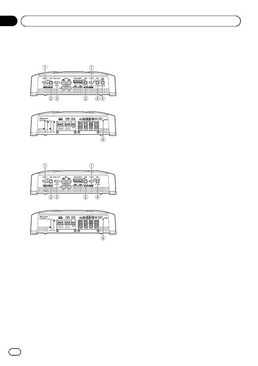
What’s what
quency range.
GM-A6604
2 GAIN (gain) control
Front side
Adjusting gain controls CHANNEL A (chan-
nel A) and CHANNEL B (channel B) helps
align the car stereo output to the Pioneer
amplifier. Default setting is the NORMAL
position.
If output remains low, even when the car
stereo volume is turned up, turn controls to
Rear side
lower level. If distortion occurs when the car
stereo volume is turned up, turn these con-
trols to higher level.
! If using only one input plug, set the gain
controls for speaker outputs A and B to
the same position.
! For use with an RCA equipped car stereo
GM-A4604
(standard output of 500 mV), set to the
Front side
NORMAL position. For use with an RCA
equipped Pioneer car stereo, with maxi-
mum output of 4 V or more, adjust level
to match that of the car stereo output.
! For use with an RCA equipped car stereo
with output of 4 V, set to the HIGH posi-
tion.
Rear side
3 INPUT SELECT (input select) switch
Select 2CH for two-channel input and 4CH
for four–channel input.
! You can select input select only for con-
nections when using the RCA input jack.
For connections when using the speaker
To adjust the switch, use a flathead screwdri-
input wire, 4CH will be used automati-
ver if needed.
cally no matter which switch setting is
selected.
1 LPF (low-pass filter)/HPF (high-pass fil-
ter) select switch
4 FREQ (cut off frequency) control
Switch the settings based on the connected
Cut off frequency selectable from 40 Hz to
speaker.
500 Hz if the LPF/HPF select switch is set to
! When the Subwoofer is connected:
LPF or HPF.
Select LPF. This eliminates high range
! You can select cut off frequency only for
frequency and outputs low range fre-
CHANNEL B.
quency.
! When the full range speaker is con-
5 BASS BOOST (bass boost level control)
nected:
switch
Select HPF or OFF. HPF eliminates low
You can select a bass boost level from 0 dB
range frequency and output high range
to 12 dB.
4
En
<5707000008290>4
Black plate (5,1)
Section
Setting the unit
02
English
! Bass boost level setting applies only to
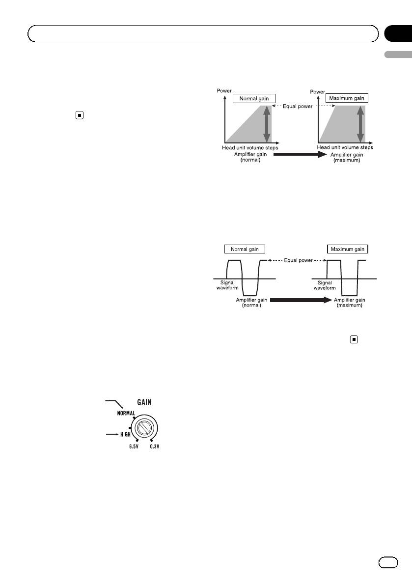
Relationship between amplifier gain
CHANNEL B (channel B) output.
and head unit output power
6 Power indicator
The power indicator lights up to indicate
power ON.
Setting gain properly
! Protective function included to prevent
malfunction of the unit and/or speakers
If amplifier gain is raised improperly, this will
due to excessive output, improper use or
simply increase distortion, with little increase
improper connection.
in power.
! When outputting high volume sound etc.,
Signal waveform when outputting at
this function cuts off the output for a few
high volume using amplifier gain
seconds as a normal function, but output
control
is restored when the volume of the head
unit is turned down.
! A cut in sound output may indicate impro-
per setting of the gain control. To ensure
continuous sound output with the head
unit at a high volume, set amplifier gain
control to a level appropriate for the preout
maximum output level of the head unit, so
that volume can remain unchanged and to
If the signal waveform is distorted due to high
control excess output.
output, even if the amplifier gain is raised, the
! Despite correct volume and gain settings,
output power will change only slightly.
the unit sound still cuts out periodically. In
such cases, please contact the nearest
authorized Pioneer Service Station.
Gain control of this unit
Preout level: 2 V
(Standard: 500 mV)
Preout level: 4 V
Above illustration shows NORMAL gain set-
ting.
5
En
<5707000008290>5
Оглавление
- Before you start
- Setting the unit
- Connecting the units
- Connections when using the RCA input jack
- Connecting the units
- Before installing the amplifier
- Additional information
- Avant de commencer
- Réglage de l’appareil
- Connexion des appareils
- Connexions lors de l’utilisation du jack d’entrée RCA
- Connexion des appareils
- Installation
- Informations complémentaires
- Prima di iniziare
- Impostazione dell’unità
- Collegamento delle unità
- Collegamenti utilizzando un connettore di ingresso RCA
- Collegamento delle unità
- Installazione
- Informazioni supplementari
- Antes de comenzar
- Configuración de la unidad
- Conexión de las unidades
- Conexiones al utilizar una toma de entrada RCA
- Conexión de las unidades
- Instalación
- Información adicional
- Bevor Sie beginnen
- Einstellen des Geräts
- Anschließen der Geräte
- Anschlüsse bei Verwendung des Cinch-Eingangs
- Anschließen der Geräte
- Installation
- Zusätzliche Informationen
- Vóór u begint
- Het toestel installeren
- De toestellen aansluiten
- Aansluiting via de RCA-ingang
- De toestellen aansluiten
- Installatie
- Aanvullende informatie
- Перед началом эксплуатации
- Настройка усилителя
- Подключение устройств
- Подключение устройств Перед подключением Режим мостового соединения усилителя
- Подключение устройств
- Подключение с использованием входного гнезда RCA
- Подключение устройств
- Установка
- Дополнительная информация Серийный номер
- Дополнительная информация


