Pioneer DEH-X8500DAB: инструкция
Раздел: Автомобильная техника
Тип: Мультимедиа
Инструкция к Мультимедиа Pioneer DEH-X8500DAB
Оглавление

CD RDS RECEIVER
AUTORADIO CD RDS
SINTOLETTORE CD RDS
English NederlandsDeutschEspañolItalianoFrançais Русский
REPRODUCTOR DE CD CON RECEPTOR RDS
CD RDS-EMPFÄNGER
CD RDS-ONTVANGER
CD RDS ПРИЕМНИК
Installation Manual
Manuel d’installation
DEH-X8500DAB
Manuale d’installazione
Manual de instalación
DEH-X8500BT
Installationsanleitung
Installatiehandleiding
DEH-X7500SD
Руководство по установке
Important
! Check all connections and systems before
final installation.
! Do not use unauthorized parts as this may
cause malfunctions.
! Consult your dealer if installation requires
drilling of holes or other modifications to the
vehicle.
! Do not install this unit where:
— it may interfere with operation of the vehicle.
— it may cause injury to a passenger as a result
of a sudden stop.
! The semiconductor laser will be damaged if
it overheats. Install this unit away from hot
places such as near the heater outlet.
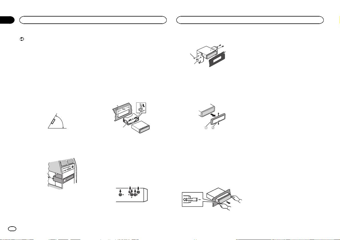
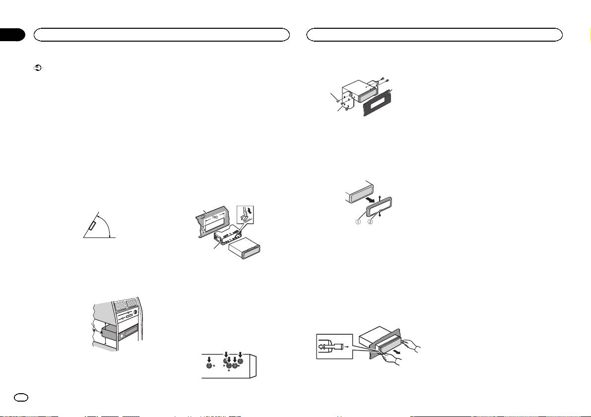
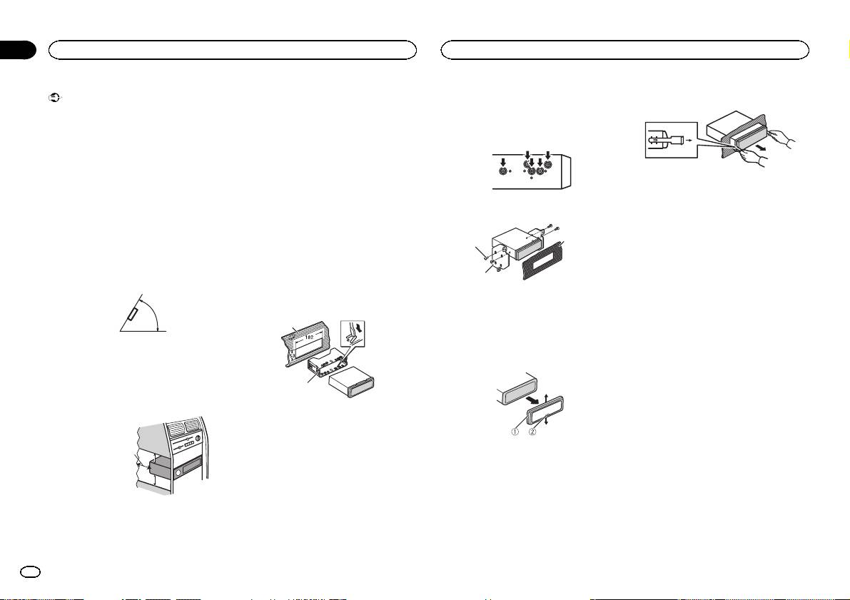
! Optimum performance is obtained when the
unit is installed at an angle of less than 60°.
60°
! When installing, to ensure proper heat dis-
persal when using this unit, make sure you
leave ample space behind the rear panel and
wrap any loose cables so they are not block-
ing the vents.
5cmcm
Section
01
Installation
Installation
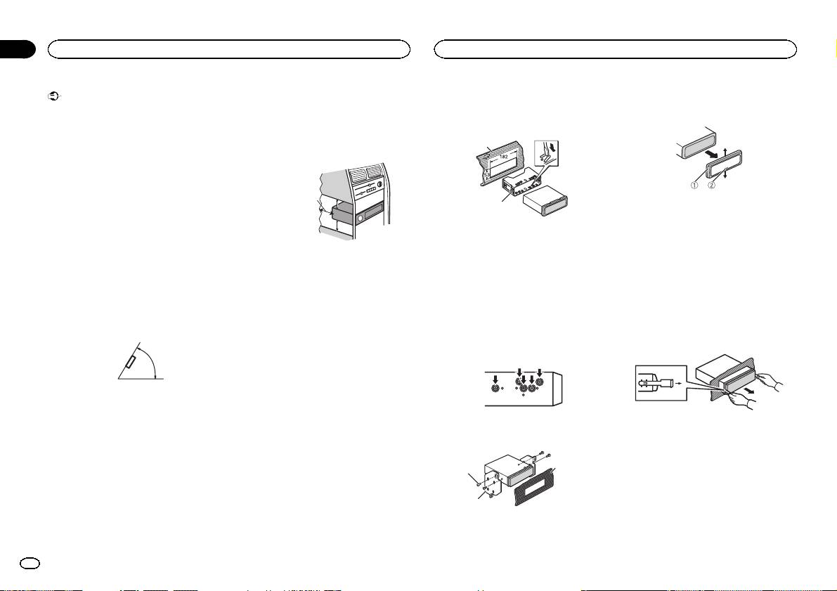
Use commercially available parts when instal-
2 Tighten two screws on each side.
Removing and re-attaching the
ling.
front panel
You can remove the front panel to protect your
DIN Front-mount
3
1
unit from theft.
1 Insert the mounting sleeve into the dash-
Press the detach button and push the front
board.
panel upward and pull it toward you.
2
For installation in shallow spaces, use the sup-
For details, refer to operation manual.
plied mounting sleeve. If there is enough space,
1 Tapping screw (5 mm × 8 mm)
use the mounting sleeve that came with the ve-
2 Mounting bracket
hicle.
3 Dashboard or console
2 Secure the mounting sleeve by using a
screwdriver to bend the metal tabs (90°) into
Removing the unit
place.
1 Remove the trim ring.
1
2
1 Trim ring
1 Dashboard
2 Notched tab
2 Mounting sleeve
! Releasing the front panel allows easier ac-
# Make sure that the unit is installed securely in
cess to the trim ring.
place. An unstable installation may cause skipping
! When reattaching the trim ring, point the
or other malfunctions.
side with the notched tab down.
DIN Rear-mount
2 Insert the supplied extraction keys into
both sides of the unit until they click into
Leave ample
1 Determine the appropriate position
5 cm
place.
space
where the holes on the bracket and the side
of the unit match.
5 cm
3 Pull the unit out of the dashboard.
DIN front/rear mount
This unit can be properly installed using either
front-mount or rear-mount installation.
2
En
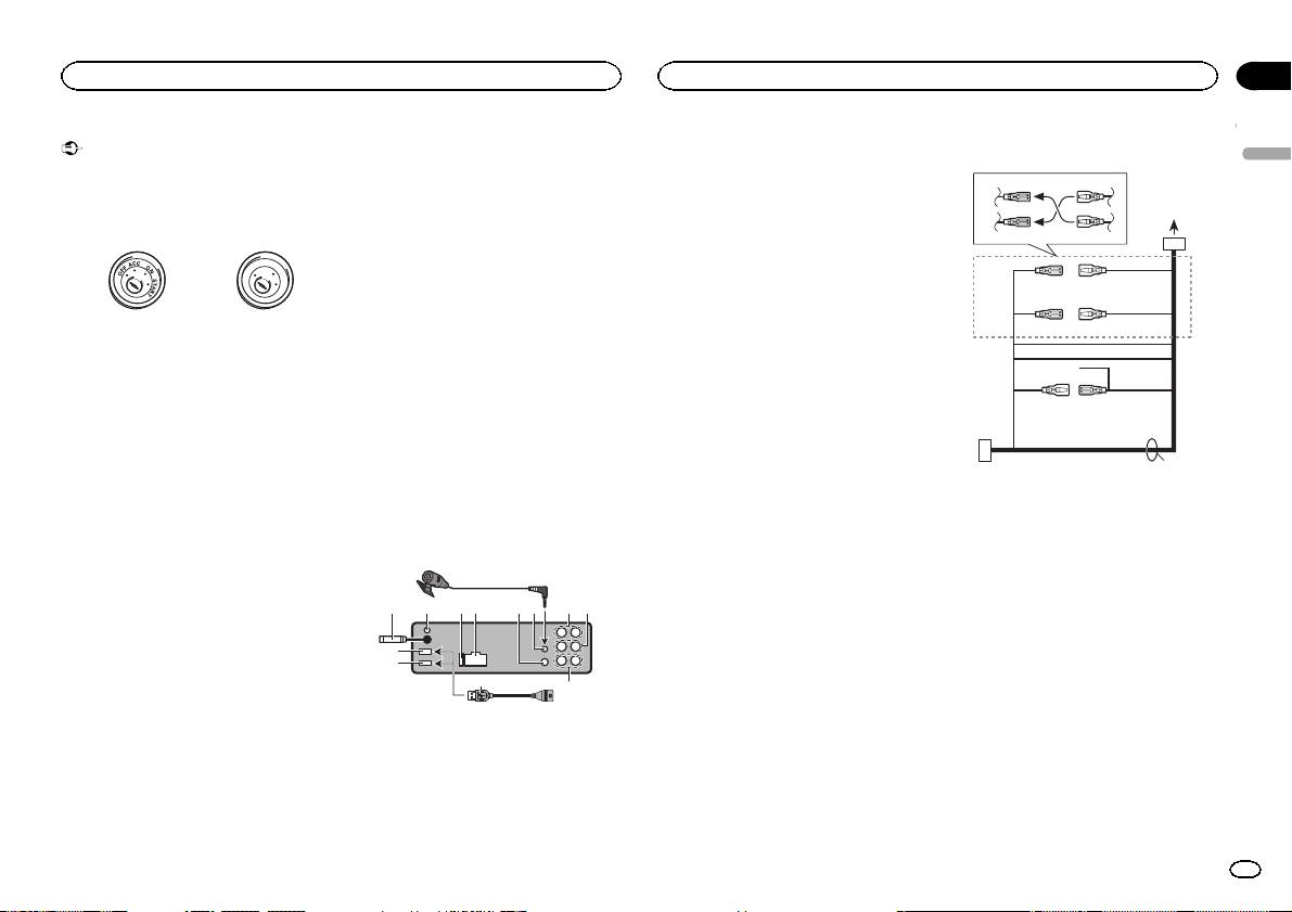
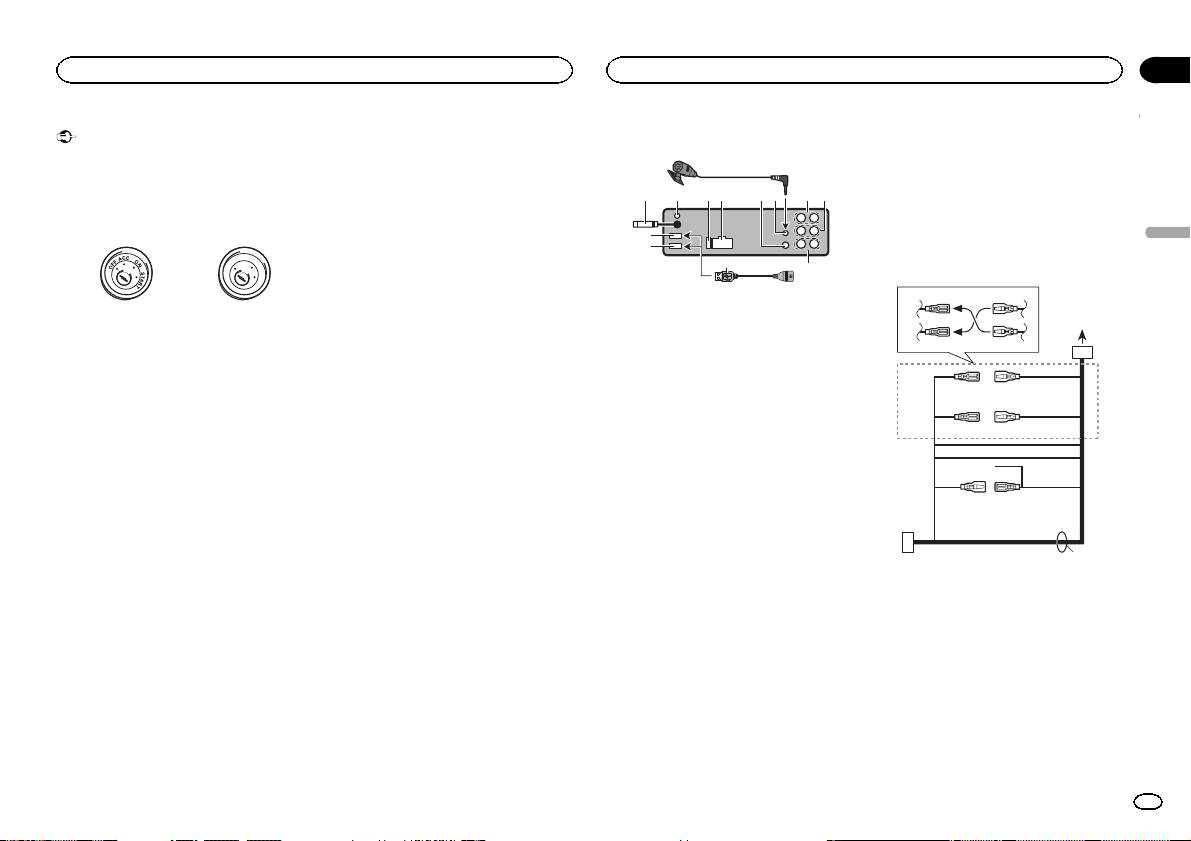
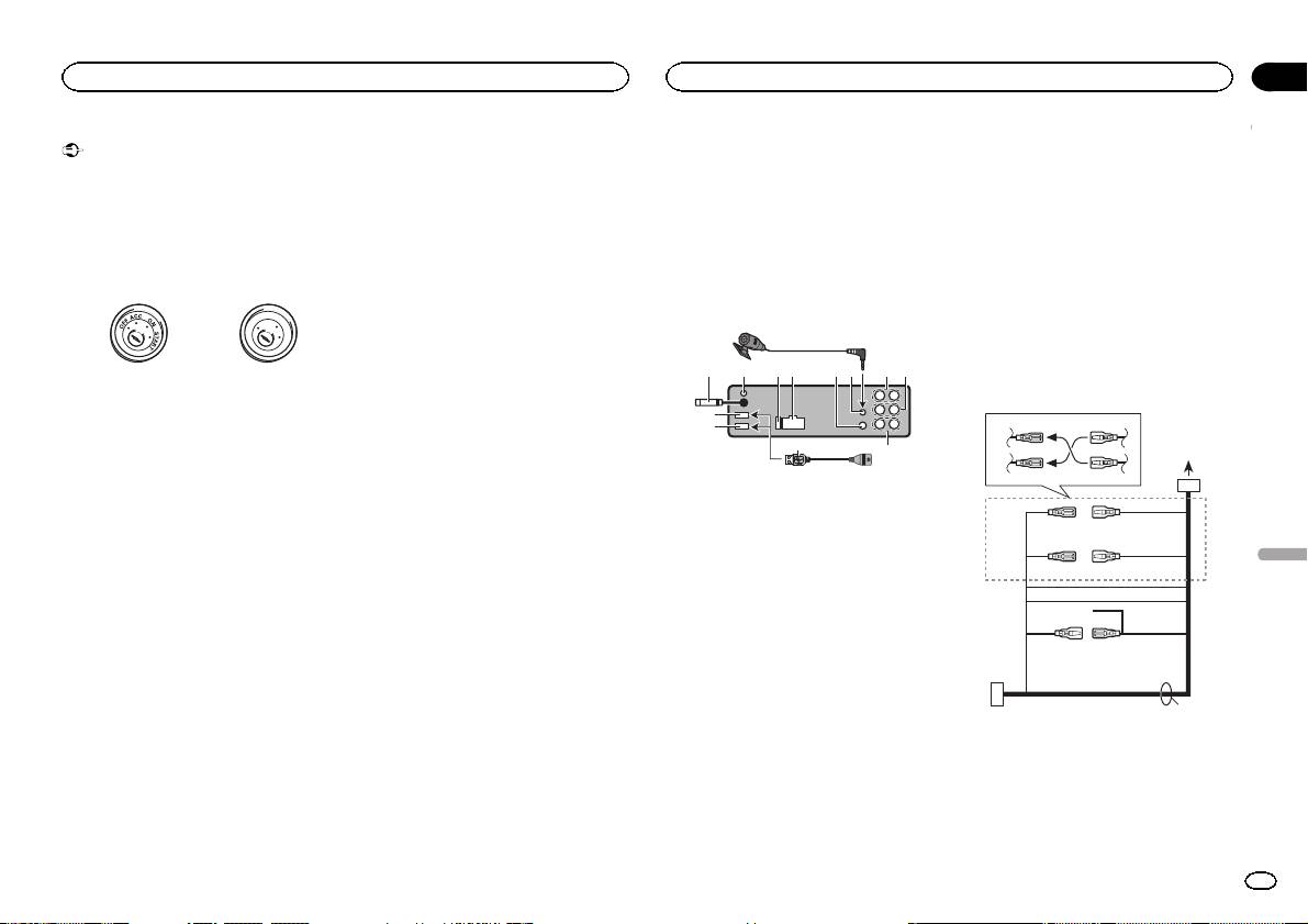
Important
— Never wire the negative speaker cable directly
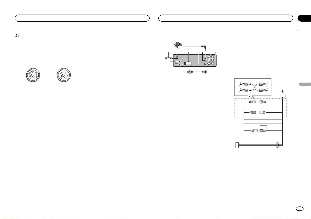
5 Fuse (10 A)
Power cord
! When installing this unit in a vehicle without
to ground.
6 Power cord input
an ACC (accessor y) position on the ignition
— Never band together negative cables of multi-
7 Wired remote input
3
4
switch, failure to connect the red cable to the
ple speakers.
Hard-wired remote control adapter can be
terminal that detects operation of the ignition
! When this unit is on, control signals are sent
connected (sold separately).
key may result in battery drain.
through the blue/white cable. Connect this
8 Microphone input (DEH-X8500DAB and
1
2
5
6
cable to the system remote control of an ex-
DEH-X8500BT only)
ternal power amp or the vehicle’s auto-anten-
9 Microphone (DEH-X8500DAB and DEH-
F
F
O
N
O
S
T
na relay control terminal (max. 300 mA
X8500BT only)
T
R
A
3
4
12 V DC). If the vehicle is equipped with a
4m
glass antenna, connect it to the antenna
a Rear output
ACC position No ACC position
booster power supply terminal.
b Front output
7
5
6
! Use of this unit in conditions other than the
! Never connect the blue/white cable to the
c Subwoofer output
8
following could result in fire or malfunction.
power terminal of an external power amp.
d USB cable
9
— Vehicles with a 12-volt battery and negative
Also, never connect it to the power terminal
1.5 m
c
grounding.
of the auto antenna. Doing so may result in
! Only for DEH-X8500DAB and DEH-X8500BT
a
b
— Speakers with 50 W (output value) and 4 W to
battery drain or a malfunction.
If connecting both USB1 (USB storage
8 W (impedance value).
! The black cable is ground. Ground cables for
device1)/iPod1 (iPod connected using
! To prevent a short-circuit, overheating or mal-
this unit and other equipment (especially,
USB input1) and USB2 (USB storage de-
e
function, be sure to follow the directions
high-current products such as power amps)
vice2)/iPod2 (iPod connected using USB
below.
must be wired separately. If they are not, an
input2) at the same time, use a Pioneer
— Disconnect the negative terminal of the bat-
accidental detachment may result in a fire or
USB cable (CD-U50E) in addition to the
tery before installation.
malfunction.
regular Pioneer USB cable.
— Secure the wiring with cable clamps or adhe-
sive tape. Wrap adhesive tape around wiring
This unit
that comes into contact with metal parts to
protect the wiring.
9
— Place all cables away from moving parts,
such as the shift lever and seat rails.
3 5 6a7 b
4
8
— Place all cables away from hot places, such
as near the heater outlet.
— Do not connect the yellow cable to the battery
2
by passing it through the hole to the engine
1
compartment.
d
c
— Cover any disconnected cable connectors
with insulating tape.
1 USB port 1
— Do not shorten any cables.
2 USB port 2 (DEH-X8500DAB and DEH-
— Never cut the insulation of the power cable of
X8500BT only)
this unit in order to share the power with
3 Antenna input
other devices. The current capacity of the
15 cm
cable is limited.
4 DAB antenna input (DEH-X8500DAB only)
— Use a fuse of the rating prescribed.
To receive DAB signals, connect a DAB an-
tenna (AN-DAB1) sold separately to the unit.
d
Section
Connections
Connections
02
English
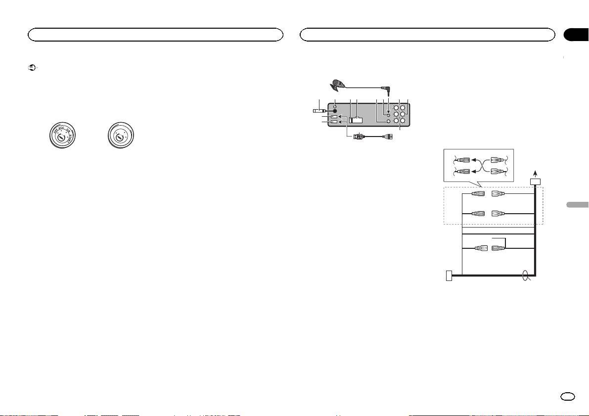
1 To power cord input
2 Depending on the kind of vehicle, the func-
tion of 3 and 5 may be different. In this
case, be sure to connect 4 to 5 and 6 to
3.
3 Yellow
Back-up (or accessory)
4 Yellow
Connect to the constant 12 V supply termi-
nal.
5 Red
Accessory (or back-up)
6 Red
Connect to terminal controlled by ignition
switch (12 V DC).
7 Connect leads of the same color to each
other.
8 Orange/white
Connect to lighting switch terminal.
9 Black (chassis ground)
En
3
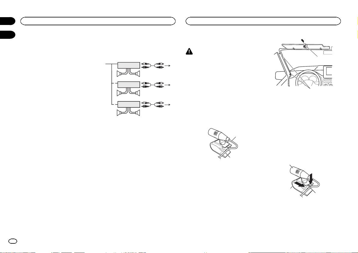
a Blue/white
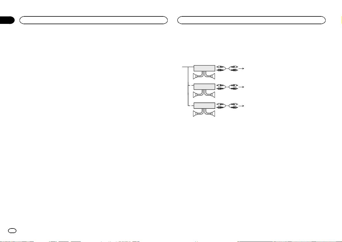
! Only for DEH-X8500DAB and DEH-X8500BT
Power amp (sold separately)
The pin position of the ISO connector will dif-
Perform these connections when using the op-
fer depending on the type of vehicle. Connect
tional amplifier.
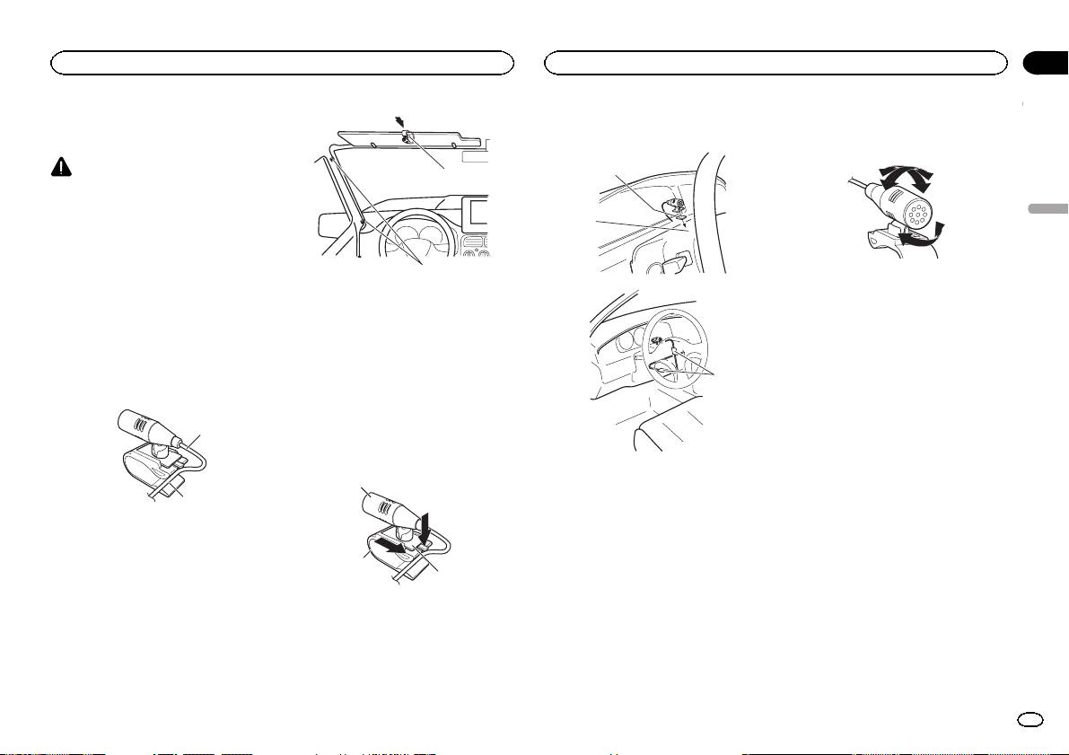
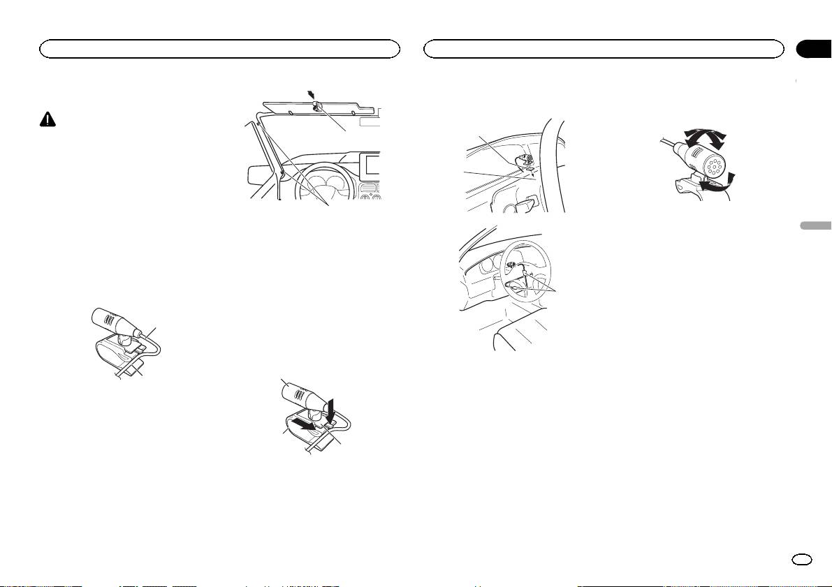
CAUTION
a and b when Pin 5 is an antenna control
It is extremely dangerous to allow the micro-
1
type. In another type of vehicle, never con-
1
3
phone lead to become wound around the steer-
nect a and b.
2
ing column or shift lever. Be sure to install the
b Blue/white
4
unit in such a way that it will not obstruct driv-
Connect to system control terminal of the
55
ing.
power amp (max. 300 mA 12 V DC).
3
c Blue/white
Note
Connect to auto-antenna relay control termi-
1
2
6
Install the microphone in a position and orienta-
nal (max. 300 mA 12 V DC).
77
tion that will enable it to pick up the voice of the
d Speaker leads
person operating the system.
White: Front left +
3
White/black: Front left *
2
Gray: Front right +
1
8
When installing the
Gray/black: Front right *
99
microphone on the sun visor
Green: Rear left + or subwoofer +
Green/black: Rear left * or subwoofer *
1 Fit the microphone lead into the groove.
1 System remote control
Violet: Rear right + or subwoofer +
Connect to Blue/white cable.
Violet/black: Rear right * or subwoofer *
2 Power amp (sold separately)
e ISO connector
1
3 Connect with RCA cable (sold separately)
In some vehicles, the ISO connector may be
4 To Rear output
divided into two. In this case, be sure to con-
5 Rear speaker
nect to both connectors.
6 To Front output
Notes
7 Front speaker
2
8 To subwoofer output
! Change the set up menu of this unit (refer to
9 Subwoofer
the operation manual). The subwoofer output
1 Microphone lead
of this unit is monaural.
2 Groove
! When using a subwoofer of 70 W (2 W), be
sure to connect the subwoofer to the violet
2 Install the microphone clip on the sun
and violet/black leads of this unit. Do not
visor.
connect anything to the green and green/
With the sun visor up, install the microphone
black leads.
clip. (Lowering the sun visor reduces the voice
recognition rate.)
2
Section
02
Connections
Installing the microphone
03
1 Microphone clip
2 Clamp
Use separately sold clamps to secure the
lead where necessary inside the vehicle.
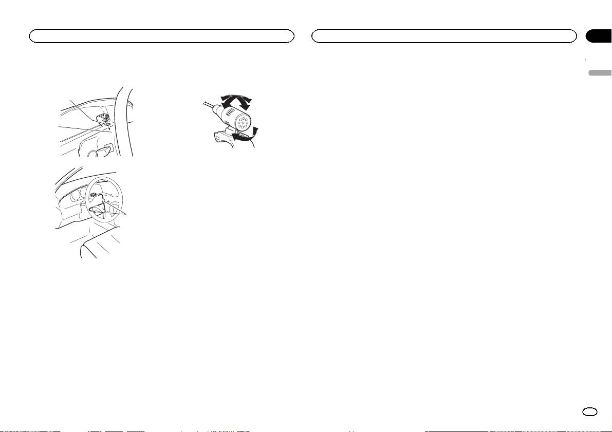
When installing the
microphone on the steering
column
1 Detach the microphone base from the mi-
crophone clip.
To detach the microphone base from the micro-
phone clip, slide the microphone base.
1
2
3
1 Microphone
2 Microphone clip
3 Microphone base
4
En
Section
Installing the microphone
03
2 Install the microphone on the steering
Adjusting the microphone
column.
English
angle
1
2
The microphone angle can be adjusted.
3
1 Double-sided tape
2 Install the microphone on the rear side of the
steering column.
3 Clamp
Use separately sold clamps to secure the
lead where necessary inside the vehicle.
En
5
Important
! Vérifiez toutes les connexions et tous les sys-
tèmes avant l’installation finale.
! N’utilisez pas de pièces non autorisées car il
peut en résulter des dysfonctionnements.
! Consultez votre revendeur si l’installation né-
cessite le perçage de trous ou d’autres modi-
fications du véhicule.
! N’installez pas cet appareil là où :
— il peut interférer avec l’utilisation du véhicule.
— il peut blesser un passager en cas d’arrêt
soudain du véhicule.
! Le laser à semi-conducteur sera endommagé
s’il devient trop chaud. Installez cet appareil
àl’écart de tous les endroits chauds, par
exemple les sorties de chauffage.
! Des performances optimales sont obtenues
quand l’appareil est installé à un angle infé-
rieur à 60°.
60°
! Lors de l’installation, pour assurer une dis-
persion correcte de la chaleur quand cet ap-
pareil est utilisé, assurez-vous de laisser un
espace important derrière la face arrière et
enroulez les câbles volants de façon qu’ils ne
bloquent pas les orifices d’aération.
5cmcm
Section
01
Installation
Installation
2 Serrez deux vis de chaque côté.
Montage avant/arrière DIN
Retrait et remontage de la face
avant
Cet appareil peut être installé correctement soit
en montage frontal ou en montage arrière.
Vous pouvez retirer la face avant pour protéger
3
1
Utilisez des pièces disponibles dans le
l’appareil contre le vol.
commerce lors de l’installation.
Appuyez sur la touche de retrait, puis poussez la
face avant vers le haut et tirez-la vers vous.
2
Montage frontal DIN
Pour plus de détails, reportez-vous au mode
d’emploi.
1 Insérez le manchon de montage dans le
1 Vis taraudeuse (5 mm × 8 mm)
tableau de bord.
2 Support de montage
Lors de l’installation de cet appareil dans un es-
3 Tableau de bord ou console
pace peu profond, utilisez le manchon de mon-
tage fourni. Si l’espace est suffisant, utilisez le
Retrait de l’appareil
manchon de montage fourni avec le véhicule.
1 Retirez l’anneau de garniture.
2 Fixez le manchon de montage en utilisant
un tournevis pour courber les pattes métalli-
ques (90°) en place.
1
1 Anneau de garniture
2 Encoche
2
! Retirer la face avant permet d’accéder plus
facilement à l’anneau de garniture.
! Quand vous remontez l’anneau de garniture,
1 Tableau de bord
pointez le côté avec l’encoche vers le bas.
2 Manchon de montage
# Assurez-vous que l’appareil est correctement mis
2 Insérez les clés d’extraction fournies dans
en place. Toute installation instable peut entraîner
les deux côtés de l’appareil jusqu’àcequ’el-
des sauts ou autres dysfonctionnements.
les s’enclenchent en place.
Montage arrière DIN
3 Tirez l’appareil hors du tableau de bord.
Laissez suffisamment
d’espace
5 cm
1 Déterminez la position appropriée où les
trous sur le support et sur le côté de l’appa-
5 cm
reil se correspondent.
6
Fr
Important
— Ne coupez jamais l’isolation du câble d’ali-
Si USB1 (périphérique de stockage USB
Cet appareil
! Lors de l’installation de cet appareil dans un
mentation de cet appareil pour partager l’ali-
1)/iPod1 (iPod connecté via l’entrée USB
véhicule sans position ACC (accessoire) sur
mentation avec d’autres appareils. La
9
1) et USB2 (périphérique de stockage
le contact d’allumage, ne pas connecter le
capacité en courant du câble est limitée.
USB 2)/iPod2 (iPod connecté via l’entrée
câble rouge à la borne qui détecte l’utilisa-
— Utilisez un fusible correspondant aux caracté-
3 5 6a7 b
4
8
USB 2) sont connectés simultanément,
tion de la clé de contact peut entraîner le dé-
ristiques spécifiées.
utilisez un câble USB Pioneer (CD-U50E)
chargement de la batterie.
— Ne câblez jamais le câble négatif du haut-par-
en plus du câble standard USB Pioneer.
leur directement à la masse.
2
1
— Ne réunissez jamais ensemble les câbles né-
F
F
O
N
O
d
S
T
gatifs de plusieurs haut-parleurs.
c
Cordon d’alimentation
R
A
T
! Lorsque cet appareil est sous tension, les si-
gnaux de commande sont transmis via le
3
4
1 Port USB 1
Avec position ACC Sans position ACC
câble bleu/blanc. Connectez ce câble à la té-
2 USB port 2 (DEH-X8500DAB et DEH-X8500BT
! L’utilisation de cet appareil dans des condi-
lécommande du système d’un amplificateur
uniquement)
1
tions autres que les conditions suivantes
de puissance externe ou à la borne de
2
5
6
3 Entrée antenne
pourrait provoquer un incendie ou un mau-
commande du relais de l’antenne motorisée
15 cm
vais fonctionnement.
du véhicule (max. 300 mA 12 V CC). Si le véhi-
4 Entrée antenne DAB (DEH-X8500DAB uni-
— Véhicules avec une batterie 12 volts et mise à
cule est équipé d’une antenne intégrée à la
quement)
3
4
la masse du négatif.
lunette arrière, connectez-le à la borne d’ali-
Pour recevoir des signaux DAB, connectez
— Haut-parleurs avec une puissance de sortie
mentation de l’amplificateur d’antenne.
une antenne DAB (AN-DAB1) vendue sépa-
7
5
6
de 50 W et une impédance de 4 W à8W.
! Ne reliez jamais le câble bleu/blanc à la
rément à l’appareil.
! Pour éviter un court-circuit, une surchauffe
borne d’alimentation d’un amplificateur de
8
5 Fusible (10 A)
9
ou un dysfonctionnement, assurez-vous de
puissance externe. De même, ne le reliez pas
6 Entrée cordon d’alimentation
c
respecter les instructions suivantes.
à la borne d’alimentation de l’antenne moto-
7 Entrée télécommande câblée
— Déconnectez la borne négative de la batterie
risée. Dans le cas contraire, il peut en résul-
Un adaptateur de télécommande câblée
a
b
avant l’installation.
ter un déchargement de la batterie ou un
(vendu séparément) peut être connecté.
— Fixez le câblage avec des serre-fils ou de la
dysfonctionnement.
8 Entrée microphone (DEH-X8500DAB et DEH-
e
bande adhésive. Pour protéger le câblage, en-
! Le câble noir est la masse. Les câbles de
X8500BT uniquement)
roulez dans du ruban adhésif les parties du
terre de cet appareil et d’autres produits (par-
9 Microphone (DEH-X8500DAB et DEH-
câblage en contact avec des pièces en métal.
ticulièrement les produits avec des courants
X8500BT uniquement)
— Placez les câbles à l’écart de toutes les par-
élevés tels que l’amplificateur de puissance)
4m
ties mobiles, telles que le levier de vitesse et
doivent être câblés séparément. Dans le cas
a Sortie arrière
les rails des sièges.
contraire, ils peuvent se détacher accidentel-
b Sortie avant
— Placez les câbles à l’écart de tous les endroits
lement et provoquer un incendie ou un dys-
c Sortie haut-parleur d’extrêmes graves
chauds, par exemple les sorties de chauf-
fonctionnement.
d Câble USB
fage.
1,5 m
— Ne reliez pas le câble jaune à la batterie à tra-
! Seulement pour DEH-X8500DAB et DEH-
vers le trou dans le compartiment moteur.
X8500BT
— Recouvrez tous les connecteurs de câbles qui
ne sont pas connectés avec du ruban adhésif
isolant.
— Ne raccourcissez pas les câbles.
d
Section
Connexions
Connexions
02
Français
1 Vers l’entrée cordon d’alimentation
2 Selon le type de véhicule, 3 et 5 peuvent
avoir une fonction différente. Dans ce cas,
assurez-vous de connecter 4 à 5 et 6 à 3.
3 Jaune
Alimentation de secours (ou accessoire)
4 Jaune
Connectez à la borne d’alimentation 12 V per-
manente.
5 Rouge
Accessoire (ou alimentation de secours)
6 Rouge
Connectez à la borne contrôlée par le
contact d’allumage (12 V CC).
Fr
7

Section
02
Connexions
Connexions
7 Connectez les fils de même couleur en-
Remarques
Amplificateur de puissance
semble.
! Changez le menu de configuration de cet ap-
(vendu séparément)
8 Orange/blanc
pareil (reportez-vous au mode d’emploi). La
Connectez à la borne du commutateur d’é-
sortie haut-parleur d’extrêmes graves de cet
Réalisez ces connexions lors de l’utilisation d’un
clairage.
appareil est monaurale.
amplificateur optionnel.
9 Noir (masse du châssis)
! Lors de l’utilisation d’un haut-parleur d’extrê-
a Bleu/blanc
mes graves de 70 W (2 W), assurez-vous de
1
3
La position des broches du connecteur ISO
2
connecter le haut-parleur d’extrêmes graves
4
est différente selon le type de véhicule.
aux fils violet et violet/noir de cet appareil. Ne
55
Connectez a et b lorsque la broche 5 est de
connectez aucun périphérique aux fils vert et
type commande de l’antenne. Dans un type
vert/noir.
3
différent de véhicule, ne connectez jamais a
1
2
et b.
6
b Bleu/blanc
77
Connectez à la borne de commande du sys-
3
tème de l’amplificateur de puissance (max.
2
300 mA 12 V CC).
1
8
c Bleu/blanc
99
Connectez à la borne de commande du relais
de l’antenne motorisée (max. 300 mA 12 V
CC).
1 Télécommande du système
d Fils des haut-parleurs
Connectez au câble bleu/blanc.
Blanc : Avant gauche +
2 Amplificateur de puissance (vendu séparé-
Blanc/noir : Avant gauche *
ment)
Gris : Avant droite +
3 Connectez avec un câble RCA (vendu séparé-
Gris/noir : Avant droite *
ment)
Vert: Arrière gauche + ou haut-parleur d’ex-
4 Vers la sortie arrière
trêmes graves +
5 Haut-parleur arrière
Vert/noir: Arrière gauche * ou haut-parleur
6 Vers la sortie avant
d’extrêmes graves *
7 Haut-parleur avant
Violet : Arrière droite + ou haut-parleur d’ex-
8 Vers la sortie haut-parleur d’extrêmes graves
trêmes graves +
9 Haut-parleur d’extrêmes graves
Violet/noir: Arrière droite * ou haut-parleur
d’extrêmes graves *
e Connecteur ISO
Dans certains véhicules, il est possible que
le connecteur ISO soit divisé en deux. Dans
ce cas, assurez-vous de connecter les deux
connecteurs.
8
Fr
! Seulement pour DEH-X8500DAB et DEH-
X8500BT
PRÉCAUTION
1
Il est extrêmement dangereux de laisser le fil du
microphone s’enrouler autour de la colonne de
direction ou du levier de vitesse. Assurez-vous
d’installer cet appareil de telle manière qu’il ne
gêne pas la conduite.
Remarque
Installez le microphone dans une position et
une orientation qui lui permette de capter la voix
de la personne qui utilise le système.
Si vous installez le
microphone sur le pare-soleil
1 Insérez le fil du microphone dans la
fente.
1
2
1 Fil du microphone
2 Rainure
2 Installez le clip microphone sur le pare-
soleil.
Avec le pare-soleil relevé, installez le clip micro-
phone. (Abaisser le pare-soleil réduit le taux de
reconnaissance vocale.)
2
Section
Installation du microphone
Installation du microphone
03
2 Installez le microphone sur la colonne de
Réglage de l’angle du
direction.
microphone
1
Français
2
L’angle du microphone peut être réglé.
1 Clip microphone
2 Serre-fils
Utilisez des serre-fils vendus séparément
pour fixer le fil là où c’est nécessaire dans le
véhicule.
3
Si vous installez le microphone
sur la colonne de direction
1 Détachez la base pour microphone du
clip microphone.
Pour détacher la base pour microphone du clip
microphone, faites-la glisser.
1 Bande double face
1
2 Installez le microphone sur la face arrière de
la colonne de direction.
3 Serre-fils
Utilisez des serre-fils vendus séparément
pour fixer le fil là où c’est nécessaire dans le
véhicule.
2
3
1 Microphone
2 Clip microphone
3 Base pour microphone
Fr
9
Importante
! Controllare tutti i collegamenti e i sistemi
prima dell’installazione finale.
! Non utilizzare componenti non approvati,
poiché potrebbero provocare malfunziona-
menti.
! Consultare il rivenditore se l’installazione ri-
chiede la trapanatura di fori o altre modifiche
del veicolo.
! Non installare questa unità se:
— potrebbe interferire con il funzionamento del
veicolo.
— potrebbe procurare lesioni al passeggero in
caso di arresto improvviso del veicolo.
! Se si surriscalda il laser a semiconduttore
potrebbe subire danni. Non installare questa
unità in luoghi soggetti a surriscaldamento,
come in prossimità delle bocchette dell’im-
pianto di riscaldamento.
! Le prestazioni ottimali si ottengono quando
l’unità viene installata con un’angolazione in-
feriore a 60°.
60°
! Durante l’installazione, per assicurare la cor-
retta dissipazione del calore quando si utiliz-
za l’unità, accertarsi di lasciare ampio spazio
dietro il pannello posteriore e avvolgere even-
tuali cavi allentati in modo che non ostrui-
scano le aperture.
5cmcm
Sezione
01
Installazione
Installazione
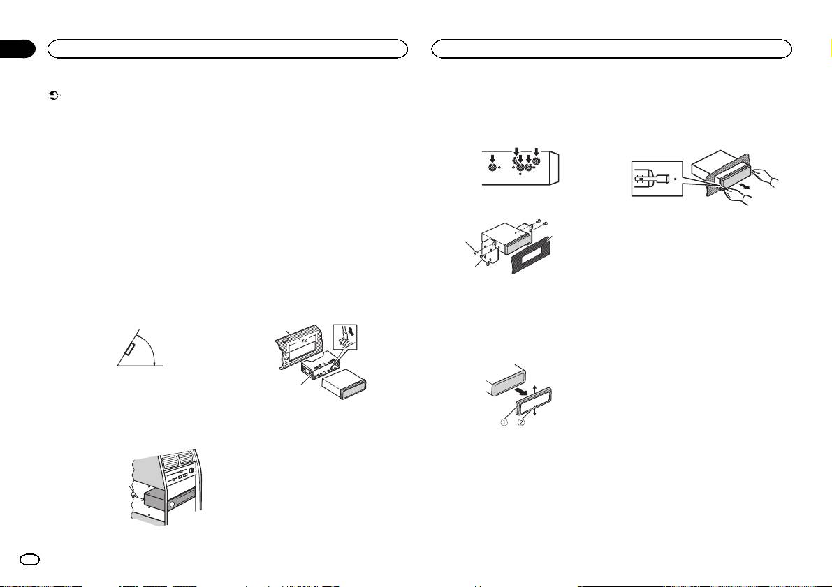
Montaggio DIN anteriore/
Montaggio DIN posteriore
2 Inserire le chiavi di estrazione fornite su
entrambi i lati dell’unità fino a che non scat-
posteriore
1 Determinare la posizione appropriata, in
tano in posizione.
modo che i fori sulla staffa e sul lato dell’uni-
Questa unità può essere installata correttamen-
tà corrispondano.
te sia dalla posizione di montaggio anteriore, sia
3 Estrarre l’unità dal cruscotto.
dalla posizione di montaggio posteriore.
Durante l’installazione utilizzare componenti di-
sponibili in commercio.
Montaggio DIN anteriore
1 Inserire la fascetta di montaggio nel cru-
2 Serrare due viti su ciascun lato.
scotto.
Se l’unità viene installata in uno spazio poco
Rimozione e reinserimento del
3
profondo, utilizzare la fascetta di montaggio for-
1
frontalino
nita. Se dietro l’unità vi è spazio sufficiente, uti-
È possibile rimuovere il frontalino per protegge-
lizzare la fascetta di montaggio fornita con il
re l’unità dai furti.
veicolo.
2
Premere il tasto di rimozione e spingere il fronta-
lino verso l’alto tirandolo verso l’esterno.
2 Assicurare la fascetta di montaggio utiliz-
1 Vite autofilettante (5 mm × 8 mm)
Per ulteriori dettagli, vedere il manuale d’istru-
zando un cacciavite per piegare le linguette
2 Staffa di montaggio
zioni.
metalliche (90°) in posizione.
3 Cruscotto o console
1
Rimozione dell’ unità
1 Rimuovere la guarnizione.
2
1 Cruscotto
2 Fascetta di montaggio
# Accertarsi che l’unità sia saldamente installata
1 Guarnizione
in posizione. Un’installazione instabile potrebbe cau-
2 Linguetta intaccata
sare salti audio o altri malfunzionamenti.
! La rimozione del frontalino permette di acce-
dere facilmente alla guarnizione.
Lasciare ampio spazio
! Quando si riapplica la guarnizione, spingere
5 cm
il lato con la linguetta intaccata verso il
basso.
5 cm
10
It
Importante
— Non condividere mai l’alimentazione con altri
Se si collegano contemporaneamente
Questa unità
! Quando si installa questa unità in un veicolo
dispositivi tagliando l’isolante del cavo di ali-
USB1 (dispositivo di memoria USB1)/
che non dispone della posizione ACC (acces-
mentazione dell’unità. La capacità di carico
9
iPod1 (iPod collegato tramite entrata
soria) per l’interruttore della chiave di avvia-
di corrente del cavo è limitata.
USB1) e USB2 (dispositivo di memoria
mento, se non si collega il cavo rosso a un
— Utilizzare esclusivamente un fusibile con la
3 5 6a7 b
4
8
USB2)/iPod2 (iPod collegato tramite en-
terminale accoppiato al funzionamento del-
portata prescritta.
trata USB2), oltre al cavo normale USB
l’interruttore della chiave di avviamento, la
— Non collegare mai direttamente a terra il
Pioneer utilizzare il cavo USB Pioneer
2
batteria potrebbe scaricarsi.
cavo negativo dell’altoparlante.
(CD-U50E).
1
— Non legare mai assieme cavi negativi di più
d
altoparlanti.
c
F
O
O
F
N
S
T
! Quando questa unità è accesa, i segnali di
Cavo di alimentazione
A
T
R
controllo vengono trasmessi dal cavo blu/
1 Porta USB 1
bianco. Collegarlo al telecomando del siste-
3
4
2 Porta USB 2 (solo per i modelli DEH-
Con posizione ACC Senza posizione ACC
ma di amplificazione di potenza o al termina-
X8500DAB e DEH-X8500BT)
! Se questa unità viene utilizzata in condizione
le di controllo del relè dell’antenna
3 Ingresso antenna
1
diverse dalle seguenti, potrebbero verificarsi
automatica del veicolo (max. 300 mA
5
6
15 cm
2
incendi o malfunzionamenti.
12 V CC). Se il veicolo è dotato di un’antenna
4 Ingresso antenna DAB (solo per il modello
— Veicoli dotati di batteria da 12 volt e messa a
a vetro, collegarla al terminale di alimentazio-
DEH-X8500DAB)
terra negativa.
ne di potenza dell’antenna.
Per ricevere segnali DAB, collegare all’unità
3
4
— Altoparlanti con uscita nominale da 50 W e
! Non collegare mai il cavo blu/bianco al ter-
un’antenna DAB (AN-DAB1) venduta a parte.
impedenza nominale compresa tra 4 W e8W.
minale di alimentazione dell’amplificatore di
5 Fusibile (10 A)
7
5
6
! Per evitare rischi di cortocircuito, surriscalda-
potenza esterno. Inoltre, non collegarlo mai
6 Ingresso cavo di alimentazione
mento o malfunzionamento, accertarsi di se-
al terminale di alimentazione dell’antenna
8
7 Ingresso telecomando cablato
9
guire le indicazioni riportate di seguito.
automatica. In caso contrario, la batteria po-
È possibile collegare un adattatore per tele-
c
— Prima dell’installazione, scollegare il morset-
trebbe scaricarsi o potrebbero verificarsi mal-
comando cablato (venduto a parte).
to negativo della batteria.
funzionamenti.
8 Ingresso microfono (solo per i modelli DEH-
a
b
— Assicurare i cavi con morsetti per cavi o na-
! Il cavo nero è la messa a terra. I cavi di
X8500DAB e DEH-X8500BT)
stro adesivo. Per proteggere i cavi, avvolgere
messa a terra di questa unità e di altre appa-
9 Microfono (solo per i modelli DEH-
e
nastro adesivo attorno agli stessi nei punti in
recchiature (soprattutto per i prodotti ad alta
X8500DAB e DEH-X8500BT)
cui entrano in contatto con parti metalliche.
tensione, quali amplificatori di potenza) de-
4m
— Posizionare tutti i cavi in modo che non pos-
vono essere collegati separatamente. In caso
a Uscita posteriore
sano entrare in contatto con componenti mo-
contrario, se scollegati accidentalmente, po-
b Uscita anteriore
bili, come la leva del cambio e i binari dei
trebbero provocare incendi o malfunziona-
c Uscita Subwoofer
sedili.
menti.
d Cavo USB
— Non posizionare i cavi in luoghi soggetti a
1,5 m
surriscaldamento, come le bocchette dell’im-
! (Solo per DEH-X8500DAB e DEH-X8500BT)
pianto di riscaldamento.
— Non collegare il cavo giallo alla batteria fa-
cendolo passare attraverso fori nel vano mo-
tore.
— Rivestire tutti i connettori scollegati con na-
stro isolante.
— Non accorciare i cavi.
d
Sezione
Collegamenti
Collegamenti
02
Italiano
1 All’ingresso del cavo di alimentazione
2 A seconda del tipo di veicolo, la funzione di
3 e 5 potrebbe essere diversa. In questo
caso, accertarsi di collegare 4 a 5 e 6 a 3.
3 Giallo
Riserva (o accessorio)
4 Giallo
Collegare al terminale di alimentazione co-
stante 12 V.
5 Rosso
Accessorio (o riserva)
It
11

Sezione
02
Collegamenti
Collegamenti
6 Rosso
! Se si usa un subwoofer da 70 W (2 W), assicu-
Amplificatore di potenza
Collegare al terminale controllato dall’inter-
rarsi di collegarlo ai fili viola e viola/nero di
(venduto a parte)
ruttore di accensione (12 V CC).
questa unità. Non collegare niente ai fili
7 Collegare insieme i cavi dello stesso colore.
verde e verde/nero.
Eseguire questi collegamenti quando si usa
8 Arancione/bianco
l’amplificatore opzionale.
Collegare al terminale dell’interruttore di illu-
1
3
minazione.
9 Nero (messa a terra telaio)
2
4
a Blu/bianco
55
La posizione dei pin del connettore ISO sarà
diversa a seconda del tipo di veicolo. Collega-
3
re a e b quando il Pin 5 è del tipo controllo
1
2
antenna. In un altro tipo di veicolo, non colle-
6
gare mai a e b.
77
b Blu/bianco
3
Collegare al terminale di controllo del siste-
2
ma dell’amplificatore di potenza (max.
1
8
300 mA 12 V CC).
99
c Blu/bianco
Collegare al terminale di controllo del relè
dell’antenna automatica (max. 300 mA 12 V
1 Telecomando sistema
CC).
Collegare al cavo Blu/bianco.
d Cavi altoparlanti
2 Amplificatore di potenza (venduto a parte)
Bianco: Anteriore sinistro +
3 Collegare con un cavo RCA (venduto a parte)
Bianco/nero: Anteriore sinistro *
4 All’uscita posteriore
Grigio: Anteriore destro +
5 Altoparlante posteriore
Grigio/nero: Anteriore destro *
6 All’uscita anteriore
Verde: Posteriore sinistro + o subwoofer +
7 Altoparlante anteriore
Verde/nero: Posteriore sinistro * o subwoo-
8 All’uscita subwoofer
fer *
9 Subwoofer
Viola: Posteriore destro + o subwoofer +
Viola/nero: Posteriore destro * o subwoofer
*
e Connettore ISO
In alcuni veicoli, il connettore ISO potrebbe
essere diviso in due. In questo caso, accertar-
si di collegare entrambi i connettori.
Note
! Cambiare il menu di configurazione dell’uni-
tà (vedere il manuale d’istruzioni). L’uscita
subwoofer di questa unità è mono.
12
It
! (Solo per DEH-X8500DAB e DEH-X8500BT)
ATTENZIONE
È estremamente pericoloso se il filo di sostegno
1
del microfono si avvolge attorno al piantone
dello sterzo o alla leva del cambio. Accertarsi
quindi di installare questa unità in modo tale da
non ostacolare la guida.
Nota
Installare il microfono in una posizione e un
orientamento tale da consentire il rilevamento
della voce della persona che utilizza il sistema.
Installazione del microfono
sull’aletta parasole
1 Inserire il cavo del microfono nella scana-
latura.
1
2
1 Cavo del microfono
2 Scanalatura
2 Installare la clip del microfono sull’aletta
parasole.
Con l’aletta parasole piegata verso l’alto, instal-
lare la clip del microfono. (Abbassare l’aletta pa-
rasole riduce la percentuale di riconoscimento
della voce.)
2
Sezione
Installazione del microfono
Installazione del microfono
03
2 Installare il microfono sul piantone dello
Regolazione dell’angolazione
sterzo.
del microfono
1
2
È possibile regolare l’angolazione del microfono.
1 Clip del microfono
Italiano
2 Morsetto
Utilizzare i morsetti venduti separatamente
per assicurare il cavo, ove necessario, all’in-
terno del veicolo.
3
Installazione del microfono
sul piantone dello sterzo
1 Scollegare la base del microfono dalla
clip del microfono.
Per scollegare la base del microfono dalla clip,
far scorrere la base del microfono.
1 Nastro biadesivo
1
2 Installare il microfono sul lato posteriore del
piantone dello sterzo.
3 Morsetto
Utilizzare i morsetti venduti separatamente
per assicurare il cavo, ove necessario, all’in-
terno del veicolo.
2
3
1 Microfono
2 Clip del microfono
3 Base del microfono
It
13
Importante
! Compruebe todas las conexiones y sistemas
antes de la instalación final.
! No utilice piezas no autorizadas, ya que pue-
den causar fallos de funcionamiento.
! Consulte a su distribuidor si para la instala-
ción es necesario taladrar orificios o hacer
otras modificaciones al vehículo.
! No instale esta unidad en un lugar donde:
— Pueda interferir con el manejo del vehículo.
— Pueda lesionar a un pasajero como conse-
cuencia de un frenazo brusco.
! El láser semiconductor se dañará si se sobre-
calienta. Instale esta unidad alejada de
zonas que alcancen altas temperaturas,
como cerca de la salida del calefactor.
! Se logra un rendimiento óptimo si la unidad
se instala en un ángulo inferior a 60°.
60°
! Cuando instale, para asegurar la dispersión
apropiada del calor durante el uso de esta
unidad, asegúrese de dejar un amplio espa-
cio por detrás del panel trasero y enrolle los
cables sueltos de modo que no bloqueen las
aberturas de ventilación.
5cmcm
Sección
01
Instalación
Instalación
Montaje delantero/posterior
Montaje trasero DIN
3 Extraiga la unidad del salpicadero.
de DIN
1 Determine la posición correcta, de modo
que los orificios del soporte y del lateral de
Esta unidad puede instalarse correctamente
la unidad coincidan.
tanto si se realiza una instalación frontal o trase-
ra.
En la instalación, emplee piezas disponibles en
el mercado.
Retirada y colocación del panel
Montaje delantero DIN
delantero
1 Inserte el manguito de montaje en el sal-
2 Apriete los dos tornillos en cada lado.
Puede extraer el panel delantero para proteger
picadero.
la unidad contra robo.
Si realiza la instalación en un espacio poco pro-
Pulse el botón de soltar, empuje el panel delan-
3
fundo, utilice el manguito de montaje suminis-
1
tero hacia arriba y tire de él hacia sí.
trado. Si hay suficiente espacio, utilice el
Si desea más información, consulte el manual
manguito de montaje que venía con el vehículo.
de instrucciones.
2
2 Fije el manguito de montaje utilizando
un destornillador para doblar las pestañas
1 Tornillo con rosca cortante (5 mm × 8 mm)
metálicas (90°) y colocarlas en su lugar.
2 Carcasa
3 Salpicadero o consola
1
Extracción de la unidad
1 Retire el anillo de guarnición.
2
1 Salpicadero
2 Manguito de montaje
# Asegúrese de que la unidad esté firmemente ins-
talada en su lugar. Una instalación inestable puede
Deje un amplio espacio
1 Anillo de guarnición
5 cm
causar saltos en el audio o un mal funcionamiento
2 Pestaña con muesca
de la unidad.
! Libere el panel delantero para acceder más
5 cm
fácilmente al anillo de guarnición.
! Al volver a colocar el anillo de guarnición,
oriente hacia abajo la pestaña con muesca.
2 Inserte en ambos lados de la unidad las
llaves de extracción provistas hasta que se
escuche un ligero chasquido.
14
Es
Importante
— Nunca corte el aislamiento del cable de ali-
Si conecta un USB1 (dispositivo de alma-
Esta unidad
! Cuando esta unidad se instale en un ve-
mentación de esta unidad para compartir la
cenamiento USB 1)/iPod1 (iPod conec-
hículo sin posición ACC (accesorio) en la
corriente con otros equipos. La capacidad de
9
tado por entrada USB 1) y un USB2
llave de encendido, el cable rojo se debe co-
corriente del cable es limitada.
(dispositivo de almacenamiento USB 2)/
nectar al terminal que pueda detectar la ope-
— Utilice un fusible con la intensidad nominal
3 5 6a7 b
4
8
iPod2 (iPod conectado por entrada USB
ración de la llave de encendido. De lo
indicada.
2) al mismo tiempo, utilice un cable USB
contrario, puede descargarse la batería.
— Nunca conecte el cable negativo de los alta-
Pioneer (CD-U50E) además del cable
voces directamente a tierra.
2
USB Pioneer habitual.
1
— Nunca empalme los cables negativos de va-
F
F
O
N
O
d
S
T
rios altavoces.
c
T
R
A
! Cuando se enciende esta unidad, se emite
Cable de alimentación
una señal de control a través del cable azul/
1 Puerto USB 1
Posición ACC Sin posición ACC
blanco. Conecte este cable al mando a dis-
3
4
2 Puerto USB 2 (solo DEH-X8500DAB y DEH-
! El uso de esta unidad en unas condiciones
tancia del sistema de un amplificador de po-
X8500BT)
distintas de las indicadas a continuación po-
tencia externo o al terminal de control del
3 Entrada de antena
1
dría causar incendios o fallos de funciona-
relé de la antena automática del vehículo
2
5
6
15 cm
miento.
(máx. 300 mA 12 V cc). Si el vehículo posee
4 Entrada de la antena DAB (solo DEH-
— Vehículos con una batería de 12 voltios y co-
una antena integrada en el cristal del para-
X8500DAB)
nexión a tierra negativa.
brisas, conéctela al terminal de la fuente de
Para recibir señales DAB, conecte una ante-
3
4
— Altavoces con 50 W (valor de salida) y 4 W a
alimentación del amplificador de la antena.
na DAB (AN-DAB1), se vende por separado.
8 W (valor de impedancia).
! Nunca conecte el cable azul/blanco al termi-
5 Fusible (10 A)
5
6
! Para evitar cortocircuitos, sobrecalentamien-
nal de potencia de un amplificador de poten-
7
6 Entrada del cable de alimentación
cia externo, ni al terminal de potencia de la
8
to o fallos de funcionamiento, asegúrese de
7 Entrada remota conectada
9
seguir las siguientes instrucciones.
antena automática, de lo contrario, puede
Es posible conectar un adaptador de mando
c
— Desconecte el terminal negativo de la batería
descargarse la batería o producirse un fallo
a distancia físicamente conectado (se vende
antes de la instalación.
de funcionamiento.
por separado).
a
b
— Asegure el cableado con pinzas para cables
! El cable negro es el cable a tierra. Los cables
8 Entrada de micrófono (solo DEH-X8500DAB
o cinta adhesiva. Envuelva con cinta adhesiva
a tierra de esta unidad y de otros productos
y DEH-X8500BT)
e
las partes en contacto con piezas metálicas
(especialmente productos de alta tensión,
9 Micrófono (solo DEH-X8500DAB y DEH-
para proteger el cableado.
como amplificadores de potencia) se deben
X8500BT)
— Mantenga los cables alejados de las partes
conectar por separado, de lo contrario,
4m
móviles, como la palanca de cambios y los
puede producirse un incendio o un fallo de
a Salida trasera
raíles de los asientos.
funcionamiento si se desconectan por acci-
b Salida delantera
— Coloque todos los cables alejados de lugares
dente.
c Salida de subgraves
calientes, como cerca de la salida del calefac-
d Cable USB
tor.
1,5 m
— No conecte el cable amarillo a la batería pa-
! Sólo para DEH-X8500DAB y DEH-X8500BT
sándolo a través del orificio hasta el compar-
timiento del motor.
— Cubra con cinta aislante los conectores de
cables que queden desconectados.
— No acorte ningún cable.
d
Sección
Conexiones
Conexiones
02
Español
1 A la toma del cable de alimentación
2 Según el tipo de vehículo, las funciones de
3 y 5 pueden ser diferentes. En este caso,
conecte 4 a 5 y 6 a 3.
3 Amarillo
Reserva (o accesorio)
4 Amarillo
Conectar al terminal de alimentación cons-
tante de 12 V.
5 Rojo
Accesorio (o reserva)
Es
15
Sección
02
Conexiones
Conexiones
6 Rojo
! Al usar un altavoz de subgraves de 70 W
Amplificador de potencia
Conectar al terminal controlado por la llave
(2 W), conecte el mismo a los cables violeta y
(se vende por separado)
de encendido (12 V CC).
violeta/negro de esta unidad. No conecte
7 Conecte entre sí los cables del mismo color.
nada al cable verde ni al verde/negro.
Realice estas conexiones cuando utilice el am-
8 Naranja/blanco
plificador opcional.
Conectar al terminal del interruptor de ilumi-
1
3
nación.
9 Negro (Toma de tierra del chasis)
2
4
a Azul/blanco
55
La posición de las patillas del conector ISO
será diferente según el tipo de vehículo. Co-
3
necte a y b cuando la patilla 5 sea del tipo
1
2
control de antena. En otro tipo de vehículo,
6
no se deben conectar nunca a y b.
77
b Azul/blanco
3
Conectar al terminal de control del sistema
2
del amplificador de potencia (máx. 300 mA
1
8
12 V CC).
99
c Azul/blanco
Conectar al terminal de control del relé de la
antena automática (máx. 300 mA 12 V CC).
1 Control remoto del sistema
d Cables de altavoces
Conexión a cable azul/blanco.
Blanco: delantero izquierdo +
2 Amplificador de potencia (se vende por sepa-
Blanco/negro: delantero izquierdo *
rado)
Gris: delantero derecho +
3 Conectar con cable RCA (se vende por sepa-
Gris/negro: delantero derecho *
rado)
Verde: trasero izquierdo + o altavoz de sub-
4 A la salida trasera
graves +
5 Altavoz trasero
Verde/negro: trasero izquierdo * o altavoz de
6 Salida delantera
subgraves *
7 Altavoz delantero
Violeta: trasero derecho + o altavoz de sub-
8 Salida de subgraves
graves +
9 Altavoz de subgraves
Violeta/negro: trasero derecho * o altavoz
de subgraves *
e Conector ISO
En algunos vehículos, el conector ISO puede
estar dividido en dos. En este caso, asegúre-
se de conectar los dos conectores.
Notas
! Modifique el menú de configuración de esta
unidad (consulte el manual de instruccio-
nes). La salida de subgraves de esta unidad
es monoaural.
16
Es

! Sólo para DEH-X8500DAB y DEH-X8500BT
PRECAUCIÓN
Es muy peligroso que el cable del micrófono se
1
enrolle alrededor de la columna de dirección o
la palanca de cambios. Asegúrese de instalar la
unidad de tal forma que no dificulte la conduc-
ción.
Nota
Instale el micrófono en una posición y orien-
tación que permita detectar la voz de la persona
que utiliza el sistema.
Instalación del micrófono en
el parasol
1 Ajuste el cable del micrófono en la ranu-
ra.
1
2
1 Cable del micrófono
2 Ranura
2 Instale la abrazadera del micrófono en el
parasol.
Levante el parasol e instale la pinza del micrófo-
no (si lo baja reduce la capacidad del reconoci-
miento de voz).
2
Sección
Instalación del micrófono
Instalación del micrófono
03
2 Instale el micrófono en la columna de di-
Ajuste del ángulo del
rección.
micrófono
1
2
Se puede ajustar el ángulo del micrófono.
1 Pinza
2 Abrazadera
Use las abrazaderas compradas por separado
para fijar el cable en los lugares del interior
del vehículo donde sea necesario.
3
Español
Instalación del micrófono en
la columna de dirección
1 Suelte la base del micrófono de la abraza-
dera del micrófono.
Para soltar la base del micrófono de la abrazade-
ra del micrófono, deslice la base del micrófono.
1 Cinta adhesiva de doble cara
1
2 Instale el micrófono en la parte trasera de la
columna de dirección.
3 Abrazadera
Use las abrazaderas compradas por separado
para fijar el cable en los lugares del interior
del vehículo donde sea necesario.
2
3
1 Micrófono
2 Pinza
3 Base del micrófono
Es
17
Wichtig
! Um beim Gebrauch des Geräts eine ord-
! Überprüfen Sie vor der endgültigen Installa-
nungsgemäße Wärmezerstreuung zu ge-
tion alle Anschlüsse und Systeme.
währleisten, ist bei der Installation genügend
! Die Verwendung nicht zugelassener Teile
Freiraum hinter der Rückseite vorzusehen.
kann eine Funktionsstörung zur Folge haben.
Lose Kabel sind aufzuwickeln, damit sie die
! Wenden Sie sich an Ihren Fachhändler, wenn
Lüftung nicht behindern.
für die Installation Löcher gebohrt oder ande-
re Änderungen am Fahrzeug vorgenommen
werden müssen.
! Installieren Sie dieses Gerät keinesfalls an
folgenden Orten:
— Orte, an denen das Gerät die Steuerung des
Fahrzeugs behindern könnte.
— Orte, an denen das Gerät die Insassen des
Fahrzeugs im Anschluss an eine Schnell-
bremsung verletzen könnte.
! Der Halbleiterlaser kann durch Überhitzung
beschädigt werden. Installieren Sie dieses
Gerät deshalb in sicherer Entfernung von Hit-
zequellen, wie z. B. Heizöffnungen.
! Optimale Leistung kann durch eine Installa-
tion des Geräts in einem Winkel unter 60° er-
zielt werden.
60°
5cmcm
Abschnitt
01
Installation
Installation
2 Befestigen Sie den Montagerahmen mit-
Entfernen des Geräts
hilfe eines Schraubendrehers: Die Metall-
1 Entfernen Sie den Einpassungsring.
klammern sind in eine sichere Position (90°)
zu biegen.
1
Reichlich Platz lassen
5 cm
2
1 Einpassungsring
2 Aussparung
5 cm
! Bei entriegelter Bedienfläche lässt sich der
1 Armaturenbrett
Einpassungsring einfacher erreichen.
2 Montagerahmen
! Halten Sie beim Wiederanbringen des Ein-
# Stellen Sie sicher, dass das Gerät fest angebracht
passungsrings die Seite mit der Aussparung
ist. Ein instabiler Einbau kann zum Aussetzen von
nach unten.
Tönen führen oder andere Fehlfunktionen verursa-
Front-/Rückmontage nach DIN
chen.
2 Führen Sie die mitgelieferten Extrak-
Dieses Gerät kann sowohl über die Front- als
tionsschlüssel an beiden Geräteseiten ein,
auch über die Rückmontage installiert werden.
DIN-Rückmontage
bis sie in der richtigen Position einrasten.
Verwenden Sie für die Montage im Handel er-
hältliches Zubehör.
1 Bestimmen Sie die geeignete Position,
3 Ziehen Sie das Gerät aus dem Armaturen-
damit die Löcher an der Klammer und den
brett.
Geräteseiten ordnungsgemäß ausgerichtet
DIN-Frontmontage
sind.
1 Führen Sie den Montagerahmen in das
Armaturenbrett ein.
Verwenden Sie den mitgelieferten Montagerah-
men, wenn bei der Installation wenig Platz zur
Verfügung steht. Bei ausreichendem Platz kann
der mit dem Fahrzeug mitgelieferte Montagerah-
men verwendet werden.
2 Ziehen Sie auf jeder Seite zwei Schrau-
Abnehmen und Wiederanbringen
ben fest.
der Frontplatte
Sie können die Frontplatte zum Schutz vor Dieb-
3
stahl abnehmen.
1
Drücken Sie die Taste zum Entriegeln der Front-
platte und schieben Sie sie nach oben und auf
Sie zu.
2
Details finden Sie in der Bedienungsanleitung.
1 Blechschraube (5 × 8 mm)
2 Montageklammer
3 Armaturenbrett oder Konsole
18
De
Wichtig
— Führen Sie das gelbe Batteriekabel nicht
! Das schwarze Kabel gewährleistet die Er-
c Subwoofer-Ausgang
! Bei der Installation des Geräts in einem
durch ein Loch in den Motorraum, um die
dung. Dieses Kabel wie auch die Erdungska-
d USB-Kabel
Kraftfahrzeug, das am Zündschalter keine
Verbindung mit der Fahrzeugbatterie herzu-
bel anderer Produkte (insbesondere von
1,5 m
Position ACC aufweist, kann es je nach An-
stellen.
Hochstromprodukten wie Leistungsverstär-
! Nur für DEH-X8500DAB und DEH-X8500BT
schlusstyp zu einer Entleerung der Fahrzeug-
— Kleben Sie freie Kabelanschlüsse mit Isolier-
ker) müssen separat verdrahtet werden. An-
Verwenden Sie beim gleichzeitigen An-
batterie kommen, wenn das rote Kabel nicht
band ab.
derenfalls kann es zu einem Brand oder
schluss von USB1 (USB-Speichermedium
mit dem Anschluss verbunden wurde, der
— Kürzen Sie die Kabel nicht.
einer Funktionsstörung kommen, wenn sich
1)/iPod1 (Über den USB-Eingang 1 ange-
für die Erkennung des Zündschlüsselbet-
— Entfernen Sie niemals die Isolierung des
die Kabel versehentlich lösen.
schlossener iPod) und USB2 (USB-Spei-
riebs verantwortlich ist.
Stromkabels dieses Geräts, um die Stromzu-
chermedium 2)/iPod2 (Über den USB-
fuhr mit einem anderen Gerät zu teilen. Da-
Eingang 2 angeschlossener iPod) zusätz-
durch wird die Stromversorgungsleistung des
Dieses Gerät
O
lich zum normalen USB-Kabel von
F
F
N
O
S
T
Kabels beeinträchtigt.
Pioneer ein weiteres USB-Kabel von
R
A
T
— Verwenden Sie eine Sicherung, die den vorge-
9
Pioneer (CD-U50E).
gebenen Leistungsmerkmalen entspricht.
Zündung mit Position
Zündung ohne Posi-
3 5 6a7 b
4
8
— Verdrahten Sie das negative Lautsprecherka-
ACC
tion ACC
bel niemals direkt mit der Erde.
Netzkabel
! Der Einsatz dieses Geräts in einer anderen
— Gruppieren Sie niemals die negativen Kabel
2
als der nachstehend angegebenen Betriebs-
mehrerer Lautsprecher.
1
3
4
umgebung kann einen Brand auslösen oder
! Wenn dieses Gerät eingeschaltet wird, liegen
d
c
eine Funktionsstörung zur Folge haben:
Steuersignale am blau/weißen Kabel an. Ver-
1
— Kraftfahrzeuge mit 12-Volt-Batterie und nega-
binden Sie dieses Kabel mit der Systemfern-
2
5
6
bedienung eines externen
1 USB-Anschluss 1
tiver Erdung.
Leistungsverstärkers oder der Steuerklemme
2 USB-Anschluss 2 (nur DEH-X8500DAB und
— Lautsprecher mit 50 W (Ausgabe) und 4 W bis
des Automatikantennenrelais des Kraftfahr-
DEH-X8500BT)
8 W (Impedanz).
3
4
3 Antenneneingang
! Um Kurzschluss, Überhitzung oder Funk-
zeugs (max. 300 mA, 12 V Gleichspannung).
tionsstörungen zu vermeiden, halten Sie sich
Wenn das Fahrzeug mit einer in die Heck-
15 cm
scheibe integrierten Radioantenne ausge-
4 DAB-Antenneneingang (nur DEH-
7
5
6
stets an die nachstehend aufgeführten An-
weisungen:
stattet ist, verbinden Sie das Kabel mit der
X8500DAB)
8
Um DAB-Signale empfangen zu können,
9
— Trennen Sie die Verbindung zur negativen An-
Versorgungsklemme des Antennenboosters.
c
schlussklemme der Fahrzeugbatterie, bevor
! Verbinden Sie das blau/weiße Kabel niemals
schließen Sie eine separat erhältliche DAB-
Sie das Gerät installieren.
mit der Leistungsklemme des externen Leis-
Antenne (AN-DAB1) an diese Einheit an.
a
b
5 Sicherung (10 A)
— Sichern Sie die Kabel mit Kabelklemmen
tungsverstärkers. Darüber hinaus darf das
oder Klebeband. Zum Schutz der Verkabe-
Kabel keinesfalls mit der Leistungsklemme
6 Netzkabelzugang
e
lung sollten die Kabel an allen Stellen, an
der Fahrzeugantenne verbunden werden. An-
7 Eingang der festverdrahteten Fernbedienung
denen sie mit Metallteilen in Berührung kom-
dernfalls kann es zu einer Entleerung oder
Es besteht die Möglichkeit, einen (separat er-
men, mit Isolierband umwickelt werden.
Funktionsstörung der Fahrzeugbatterie kom-
hältlichen) festverdrahteten Fernbedienungs-
— Bringen Sie die Kabel in sicherer Entfernung
men.
adapter anzuschließen.
8 Mikrofoneingang (nur DEH-X8500DAB und
von beweglichen Fahrzeugkomponenten, wie
DEH-X8500BT)
z. B. Schalthebel und Sitzschienen, an.
9 Mikrofon (nur DEH-X8500DAB und DEH-
— Bringen Sie die Kabel in größtmöglicher Ent-
X8500BT)
fernung von Stellen an, die sich erhitzen, wie
4m
z. B. die Heizungsöffnung.
a Heckausgang
b Frontausgang
d
Abschnitt
Anschlüsse
Anschlüsse
02
Deutsch
1 Zum Netzzugang
2 Je nach Fahrzeugtyp können die Funktionen
3 und 5 variieren. Stellen Sie in diesem Fall
sicher, dass der Anschluss von 4 nach 5
und 6 nach 3 erfolgt.
3 Gelb
Reserveversorgung (oder Zubehör)
De
19

Abschnitt
02
Anschlüsse
Anschlüsse
4 Gelb
e ISO-Anschluss
Leistungsverstärker (separat
Verbindung mit der Klemme der konstanten
Bei manchen Fahrzeugtypen kann der ISO-
erhältlich)
12-V-Spannungsversorgung.
Anschluss zweigeteilt sein. Stellen Sie in die-
5 Rot
sem Fall sicher, dass zu beiden Anschlüssen
Führen Sie diese Verkabelungen beim Gebrauch
Zubehör (oder Reserveversorgung)
Verbindungen hergestellt werden.
eines optionalen Verstärkers durch.
6 Rot
Hinweise
1
3
Verbindung mit der Klemme der zündungs-
! Ändern Sie das Setup-Menü dieses Geräts
gesteuerten Spannungsversorgung (12 V
2
(Details siehe Bedienungsanleitung). Die
4
Gleichspannung).
Subwoofer-Ausgabe dieses Geräts erfolgt in
55
7 Verbinden Sie jeweils Anschlüsse derselben
Mono.
Farbe miteinander.
3
! Bei Verwendung eines 70-W-Subwoofers
8 Orange/weiß
1
2
(2 W) muss sichergestellt werden, dass der
An die Klemme des Lichtschalters anschlie-
6
Subwoofer am violetten und violett/schwar-
ßen.
77
zen-Anschluss dieses Geräts angeschlossen
9 Schwarz (Fahrgestell-Erdung)
3
wird. Schließen Sie nichts an den grünen
a Blau/Weiß
2
und grün/schwarzen-Anschluss an.
Die Pin-Position des ISO-Anschlusses variiert
1
8
je nach Fahrzeugtyp. Wird Pin 5 zur Steue-
99
rung der Antenne verwendet, verbinden Sie
a und b. Verbinden Sie in jedem anderen
Fahrzeugtyp niemals a und b.
1 Systemfernbedienung
b Blau/Weiß
Verbindung mit blau/weißem Kabel.
Verbindung mit der Systemsteuerungsklem-
2 Leistungsverstärker (separat erhältlich)
me des Leistungsverstärkers (max. 300 mA,
3 Mit dem Cinch-Kabel (separat erhältlich) ver-
12 V Gleichspannung).
binden
c Blau/Weiß
4 Zum Heckausgang
Verbindung mit der Steuerungsklemme des
5 Hecklautsprecher
Automatikantennenrelais (max. 300 mA 12 V
6 Zum Frontausgang
Gleichspannung).
7 Vorderer Lautsprecher
d Lautsprecherkabel
8 Zum Subwoofer-Ausgang
Weiß: Vorn links +
9 Subwoofer
Weiß/Schwarz: Vorn links *
Grau: Vorn rechts +
Grau/Schwarz: Vorn rechts *
Grün: Hinten links + oder Subwoofer +
Grün/Schwarz: Hinten links * oder Subwo-
ofer *
Violett: Hinten rechts + oder Subwoofer +
Violett/Schwarz: Hinten rechts * oder Sub-
woofer *
20
De
- 1
- 2
