Pioneer DJM-5000: инструкция
Раздел: Музыкальное Оборудование
Тип: Микшерный Пульт
Инструкция к Микшерному Пульту Pioneer DJM-5000

DRB1492-B
1
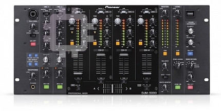
DJ MIXER
TABLE DE MIXAGE
DJ-MISCHPULT
MIXER PER DJ
DJM-5000
DJ MENGPANEEL
MESA DE MEZCLAS DJ
DJ микшерный пульт
http://www.prodjnet.com/support/
The Pioneer website listed above provides answers to frequently asked questions, information about
software, and other up-to-date data of assistance to our customers.
http://www.prodjnet.com/support/
Le site Web de Pionner ci-dessus fournit des réponses aux questions souvent posées, des informations
au sujet des logiciels et d’autres données mises à jour afin de venir en aide à notre clientèle.
http://www.prodjnet.com/support/
Auf der oben angegebenen Pioneer-Website werden unseren Kunden Antworten auf häufig gestellte
Fragen, Informationen über Software und weitere Unterstützung mit neuesten Daten angeboten.
Operating Instructions
Mode d’emploi
Bedienungsanleitung
Istruzioni per l’uso
Handleiding
Manual de instrucciones
Инструкции по эксплуатации
2
En
DRB1492-B
Thank you for buying this Pioneer product. Please read through these operating instructions so you will know how to operate your model properly. After you have fin-
ished reading the instructions, put them away in a safe place for future reference.
In some countries or regions, the shape of the power plug and power outlet may sometimes differ from that shown in the explanatory drawings. However the method of
connecting and operating the unit is the same.
2
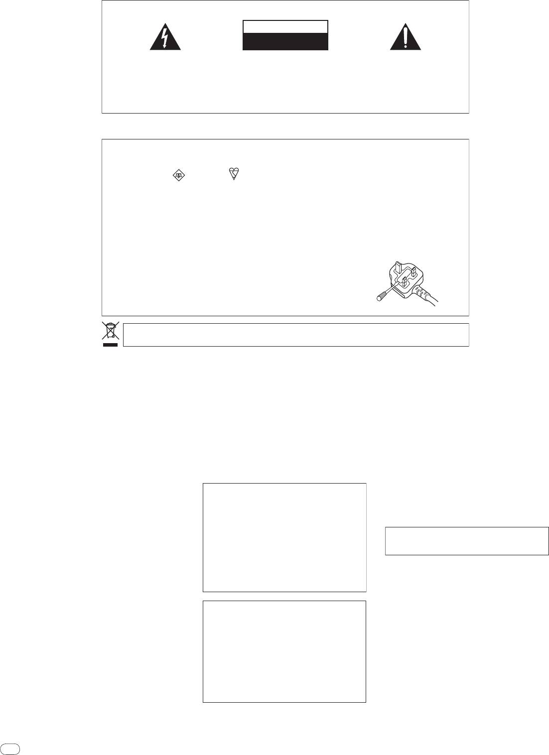
IMPORTANT
CAUTION
RISK OF ELECTRIC SHOCK
DO NOT OPEN
The lightning flash with arrowhead symbol,
CAUTION:
The exclamation point within an equilateral
within an equilateral triangle, is intended to
TO PREVENT THE RISK OF ELECTRIC
triangle is intended to alert the user to the
alert the user to the presence of uninsulated
SHOCK, DO NOT REMOVE COVER (OR
presence of important operating and
“dangerous voltage” within the product’s
BACK). NO USER-SERVICEABLE PARTS
maintenance (servicing) instructions in the
enclosure that may be of sufficient
INSIDE. REFER SERVICING TO QUALIFIED
literature accompanying the appliance.
magnitude to constitute a risk of electric
SERVICE PERSONNEL.
shock to persons.
D3-4-2-1-1_A1_En
Replacement and mounting of an AC plug on the power supply cord of this unit should be performed only by qualified
service personnel.
IMPORTANT: THE MOULDED PLUG
This appliance is supplied with a moulded three pin mains plug for your safety and convenience. A 5 amp fuse is fitted in this plug. Should the
fuse need to be replaced, please ensure that the replacement fuse has a rating of 5 amps and that it is approved by ASTA or BSI to BS1362.
Check for the ASTA mark or the BSI mark on the body of the fuse.
If the plug contains a removable fuse cover, you must ensure that it is refitted when the fuse is replaced. If you lose the fuse cover the plug
must not be used until a replacement cover is obtained. A replacement fuse cover can be obtained from your local dealer.
If the fitted moulded plug is unsuitable for your socket outlet, then the fuse shall be removed and the plug cut off and disposed of
safely. There is a danger of severe electrical shock if the cut off plug is inserted into any 13 amp socket.
If a new plug is to be fitted, please observe the wiring code as shown below. If in any doubt, please consult a qualified electrician.
IMPORTANT: The wires in this mains lead are coloured in accordance with the following code:
Blue : Neutral Brown : Live
As the colours of the wires in the mains lead of this appliance may not correspond with the coloured markings identifying the terminals in
your plug, proceed as follows ;
The wire which is coloured BLUE must be connected to the terminal which is marked with the
letter N or coloured BLACK.
The wire which is coloured BROWN must be connected to the terminal which is marked with the
letter L or coloured RED.
How to replace the fuse: Open the fuse compartment with a screwdriver and replace the fuse.
D3-4-2-1-2-2_B_En
If you want to dispose this product, do not mix it with general household waste. There is a separate collection system for used
electronic products in accordance with legislation that requires proper treatment, recovery and recycling.
Private households in the member states of the EU, in Switzerland and Norway may return their used electronic products free of charge to
designated collection facilities or to a retailer (if you purchase a similar new one).
For countries not mentioned above, please contact your local authorities for the correct method of disposal.
By doing so you will ensure that your disposed product undergoes the necessary treatment, recovery and recycling and thus prevent potential
negative effects on the environment and human health.
K058b_A1_En
WARNING
This equipment is not waterproof. To prevent a fire
or shock hazard, do not place any container filled
with liquid near this equipment (such as a vase or
flower pot) or expose it to dripping, splashing, rain
or moisture.
D3-4-2-1-3_B_En
WARNING
Before plugging in for the first time, read the following
section carefully.
The voltage of the available power supply differs
according to country or region. Be sure that the
power supply voltage of the area where this unit
will be used meets the required voltage (e.g., 230V
or 120V) written on the rear panel.
D3-4-2-1-4_A_En
WARNING
To prevent a fire hazard, do not place any naked
flame sources (such as a lighted candle) on the
equipment.
D3-4-2-1-7a_A_En
VENTILATION CAUTION
When installing this unit, make sure to leave space
around the unit for ventilation to improve heat
radiation (at least 5 cm at rear, and 3 cm at each
side).
WARNING
Slots and openings in the cabinet are provided for
ventilation to ensure reliable operation of the
product, and to protect it from overheating. To
prevent fire hazard, the openings should never be
blocked or covered with items (such as newspapers,
table-cloths, curtains) or by operating the
equipment on thick carpet or a bed.
D3-4-2-1-7b_A_En
Operating Environment
Operating environment temperature and humidity:
+5 °C to +35 °C (+41 °F to +95 °F); less than 85 %RH
(cooling vents not blocked)
Do not install this unit in a poorly ventilated area, or in
locations exposed to high humidity or direct sunlight (or
strong artificial light)
D3-4-2-1-7c*_A1_En
If the AC plug of this unit does not match the AC
outlet you want to use, the plug must be removed
and appropriate one fitted. Replacement and
mounting of an AC plug on the power supply cord of
this unit should be performed only by qualified
service personnel. If connected to an AC outlet, the
cut-off plug can cause severe electrical shock. Make
sure it is properly disposed of after removal.
The equipment should be disconnected by removing
the mains plug from the wall socket when left unused
for a long period of time (for example, when on
vacation).
D3-4-2-2-1a_A1_En
CAUTION
The POWER switch on this unit will not completely
shut off all power from the AC outlet. Since the
power cord serves as the main disconnect device for
the unit, you will need to unplug it from the AC outlet
to shut down all power. Therefore, make sure the
unit has been installed so that the power cord can
be easily unplugged from the AC outlet in case of an
accident. To avoid fire hazard, the power cord should
also be unplugged from the AC outlet when left
unused for a long period of time (for example, when
on vacation).
D3-4-2-2-2a_A_En
POWER-CORD CAUTION
Handle the power cord by the plug. Do not pull out the
plug by tugging the cord and never touch the power
cord when your hands are wet as this could cause a
short circuit or electric shock. Do not place the unit, a
piece of furniture, etc., on the power cord, or pinch the
cord. Never make a knot in the cord or tie it with other
cords. The power cords should be routed such that they
are not likely to be stepped on. A damaged power cord
can cause a fire or give you an electrical shock. Check
the power cord once in a while. When you find it
damaged, ask your nearest PIONEER authorized
service center or your dealer for a replacement.
S002*_En
When using this product follow the instructions
written on the underside of the unit, which
concern rated voltage, etc.
D3-4-2-2-4_En

English
En
3
DRB1492-B
Contents
How to read this manual
The names of displays, menus, and buttons in this manual are enclosed in brack-
ets. (e.g. [Collection] pane, [File] menu, [f])
Before start
Features ...........................................................................................................................4
What’s in the box .............................................................................................................4
Connections
Rear Panel .......................................................................................................................5
Connecting input terminals ...........................................................................................6
Connecting output terminals .........................................................................................6
Connecting to the control panel ....................................................................................7
Connecting a computer ..................................................................................................7
About the USB audio driver software ............................................................................7
About USB-MIDI channel setting ..................................................................................9
Operations
Control Panel .................................................................................................................11
Operating the DJ section..............................................................................................12
Operating the MC section ............................................................................................13
Operating the PA section .............................................................................................14
Additional information
Troubleshooting ............................................................................................................15
About the exemption clauses ......................................................................................15
Block Diagram...............................................................................................................16
Specifications ................................................................................................................17
Mounting on a rack conforming to EIA
standards
The screw holes on the left and right of the control panel of this unit match 5U size
of any EIA standard 19-inch rack. The maximum depth of this unit is 225.1 mm.
! Secure this unit with screws (not supplied) matching the rack.
! Do not install this unit directly above a power amplifier. Heat radiating from the
power amplifier may damage this unit. Also, noise (hum noise, etc.) may be
generated.
! When transporting this unit, remove it from the rack. Transporting this unit
without removing it from the rack may damage this unit.
! If you transport this unit without removing it from the rack, make sure vibration
or shock is not applied to this unit.
3

4
En
DRB1492-B
PA Section
Before start
“MASTER/
ZONE Split Output” that makes individual
performances possible in 2 separate venues with only
one device (page 14)
Features
! This unit is equipped with 2-channel output independently assigned to
The DJM-5000 is a high quality, high performance mixer designed for high sound
MASTER output and ZONE output. You can output sound in separate chan-
quality and equipped with many functions offering powerful support for three
nels to 2 venues, realizing a flexible party performance according to the atmo-
roles: MC, DJ and PA.
sphere of each venue. Likewise, you can output sound from a microphone
High sound quality processing with 96 kHz sampling, 24-bit high quality A/
D
to a selected destination, realizing an announcement or an MC performance
converter and 32-bit DSP achieves powerful, high grade sound.
according to the atmosphere of each venue.
A user-friendly panel layout arranging the three roles (MC, DJ and PA) in sepa-
rate sections for makes for intuitive operation of the many functions.
“SOUND MAXIMIZER” that can realize the sound setting
optimized for specific conditions or atmospheres (page 14)
MC Section
! This unit is equipped with the “DYNAMICS” and “CLARITY” knobs used to
adjust the sound quality. You can generate a deep bass sound in the low-fre-
quency range and a crispy clear sound in the mid- and high-frequency range,
Microphone features failthfully realizing a high-quality
which has never been possible with an equalizer. As you can easily adjust
MC performance (page 13)
the sound quality in the low- and high-frequency range, you can realize an
optimum sound setting according to the progress of a party. Also for a com-
! This unit is equipped with 2 exclusive channels for a microphone that can be
pressed sound format like MP3, the sound lost in the low- and high-frequency
operated intuitively. As you can control the volume and the 3-band equalizer
range is reinforced.
independently, you can adjust the volume and quality of sound according to
the voice of an MC in each channel.
! This unit is also equipped with 4 exclusive types of effects for a microphone
(REVERB/
ECHO+VERB/
OCTAVER/
PITCH). It is possible to carry out a vari-
What’s in the box
ety of performances with a microphone.
! USB Cable
! CH1 in the DJ section is also available for a microphone input. You can use
! CD-ROM
up to 3 microphones simultaneously.
! Warranty card
! Operating instructions (this document)
1
The world’s first
, “Advanced Talkover” feature (page 13)
! This unit is equipped with the “Advanced Talkover” feature that makes the
sound from a microphone more listenable by automatically lowering the
volume in the frequency range of voice against music. The volume of music
is not affected by using a microphone, making it possible for you to continue
with an MC performance without hurting the atmosphere of the venue (the
music level can be adjusted with the knob on the control panel).
1 As of 8/
10/
2009, for a DJ mixer, as determined by Pioneer.
DJ Section
A built-in “USB audio interface” that makes it possible to
input audio directly from a computer (page 7)
! This unit has a built-in “USB audio interface” that can input audio being
played back on a computer to a mixer via USB connection to the computer.
This makes it possible for you to realize a DJ performance using a computer
without an external sound card.
2
! You can mix up to 3-channel
audio assigned each CH of DJM-5000 with only
one computer.
2 A CD-ROM with a driver software is supplied (compatible with Windows
and Mac). You can use the audio interface feature by installing the driver
software in your computer (For Windows, you can assign 3-channel audio
only when an ASIO-compatible software is used).
The “Assignable USB MIDI” feature that can control a
MIDI-compatible DJ software (page 9)
! This unit is equipped with the “Assignable USB MIDI” feature that can trans-
mit the operation information of almost all buttons and faders on DJM-5000
to a DJ software in MIDI signals via USB connection to a computer. You can
also use it as a MIDI controller with flexible operability.
4
Оглавление
- Contents
- Before start
- Connections
- Operations
- Additional information
- Sommaire
- Informations
- Raccordements
- Opérations
- Informations supplémentaires
- Inhalt
- Vor der
- Anschlüsse
- Bedienungen
- Zusätzliche Informationen
- Indice
- Prima di cominciare
- Collegamenti
- Operazioni
- Informazioni aggiuntive
- Inhoud
- Alvorens te
- Aansluitingen
- Bediening
- Aanvullende informatie
- Contenido
- Antes de empezar a
- Conexiones
- Operaciones
- Información adicional
- Содержание
- До начала
- Подключения
- Операции
- Дополнительная информация


