Pioneer GM-D9500F: инструкция
Раздел: Музыкальное Оборудование
Тип: Усилитель Мощности
Инструкция к Усилителю Мощности Pioneer GM-D9500F

English Nederlands
BRIDGEABLE FOUR-CHANNEL POWER AMPLIFIER
AMPLIFICATEUR DE PUISSANCE PONTABLE A QUATRE VOIES
AMPLIFICATORE DI POTENZA A QUATTRO CANALI COLLEGABILE A PONTE
Français
AMPLIFICADOR DE POTENCIA DE CUATRO CANALES EN PUENTE
UBERBRUCKBARER 4-KANAL-LEISTUNGSVERSTARKER
BRUGSCHAKELBARE VIERKANAALS EINDVERSTERKER
ЧЕТЫРЕХКАНАЛЬНЫЙ УСИЛИТЕЛЬ МОЩНОСТИ С ВОЗМОЖНОСТЬЮ МОСТОВОГО ВКЛЮЧЕНИЯ
Italiano Español Deutsch
GM-D9500F
Owner’s Manual
Mode d’emploi
Manuale d’istruzioni
Manual de instrucciones
Bedienungsanleitung
Русский
Handleiding
Руководство пользователя
<YRD5289-A/S> <1>

Contents
Thank you for purchasing this PIONEER product.
To ensure proper use, please read through this manual before using this product.
Please keep the manual in a safe and accessible place for future reference.
Before you start
In case of trouble 3
Before connecting/installing the amplifier 3
Setting the Unit
What’s what 5
Setting gain properly 5
Connecting the units
Connection diagram 7
Before connecting the amplifier 7
About bridged mode 8
About suitable specification of speaker 8
Connecting the speakers 8
Connections when using the RCA input
jack 10
Connections when using the speaker input
wire 10
Connecting the power terminal 11
Connecting the speaker output
terminals 12
Installation
Before installing the amplifier 13
Example of installation on the floor mat or
chassis 13
Additional information
Specifications 14
2
En
Section
Before you start
01
English
the car battery positive terminal + and the
ground wire to the car body.
! This unit is for vehicles with a 12 V battery and
negative grounding. Before installing in re-
creational vehicles, trucks or buses, check the
battery voltage.
If you want to dispose this product, do not mix
! The black cable is ground. When installing
it with general household waste. There is a se-
this unit, make sure to connect the ground
parate collection system for used electronic
wire first. Ensure that the ground wire is prop-
products in accordance with legislation that re-
erly connected to metal parts of the car’s
quires proper treatment, recovery and recy-
body. The ground wire of the one of this unit
cling.
must be connected to the car separately with
different screws. If the screw for the ground
wire loosens or falls out, it could result in fire,
Private households in the member states of
generation of smoke or malfunction.
the EU, in Switzerland and Norway may return
! Use a fuse of the rating prescribed.
their used electronic products free of charge
! Check the connections of the power supply
to designated collection facilities or to a retai-
and speakers if the fuse of the separately sold
ler (if you purchase a similar new one).
battery wire or the amplifier fuse blows. Deter-
For countries not mentioned above, please
mine and resolve the cause, then replace the
contact your local authorities for the correct
fuse with identical equivalent.
method of disposal.
! Always install the amplifier on a flat surface.
By doing so you will ensure that your disposed
Do not install the amplifier on a surface that
product undergoes the necessary treatment,
is not flat or on a surface with a protrusion.
recovery and recycling and thus prevent po-
Doing so could result in malfunction.
tential negative effects on the environment
! When installing the amplifier, do not allow
and human health.
parts such as extra screws to get caught be-
tween the amplifier and the automobile.
Doing so could cause malfunction.
! Do not allow this unit to come into contact
In case of trouble
with liquids. Electrical shock could result.
Should this product fail to operate properly,
Also, damage to this unit, smoke, and over-
please contact your dealer or nearest author-
heating could result from contact with liquids.
ized Pioneer Service Station.
The surfaces of the amplifier and any attached
speakers may also heat up and cause minor
burns.
! In the event of any abnormality, the power
supply to the amplifier is cut off to prevent
Before connecting/
equipment malfunction. If this occurs, switch
installing the amplifier
the system power OFF and check the power
supply and speaker connections. If you are un-
WARNING
able to determine the cause, please contact
! The use of a special red battery and ground
your dealer.
wire RD-223, available separately, is recom-
! Disconnect the negative terminal of the bat-
mended. Connect the battery wire directly to
tery before installation.
3
En

Section
01
Before you start
CAUTION
! Always keep the volume low enough to hear
outside sounds.
! Extended use of the car stereo while the en-
gine is at rest or idling may exhaust the
battery.
4
En
Section
Setting the Unit
02
English
output of 4 V or more, adjust level to
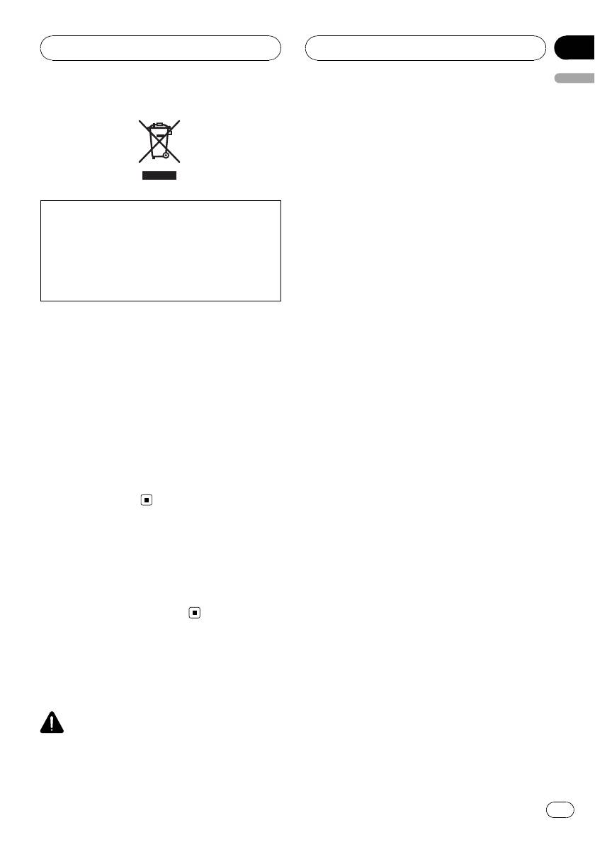
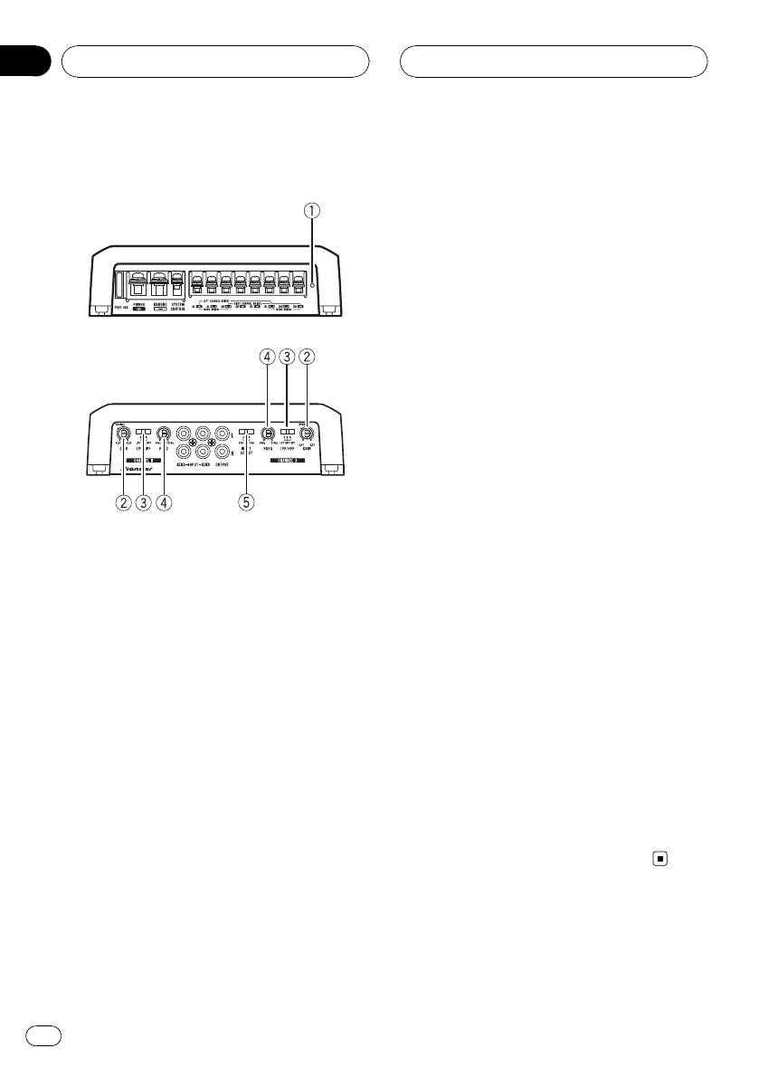
What’s what
match that of the car stereo output.
Front side
3 LPF (low-pass filter)/HPF (high-pass fil-
ter) select switch
Switch the settings based on the connected
speaker.
! When the Subwoofer is connected:
Select LPF. This eliminates high range
frequency and outputs low range fre-
Rear side
quency.
! When the full range speaker is con-
nected:
Select HPF or OFF. HPF eliminates low
range frequency and output high range
frequency. OFF outputs the entire fre-
quency range.
4 FREQ (cut off frequency) control
Cut off frequency selectable from 40 Hz to
To adjust the switch, use a flathead screwdri-
500 Hz if the LPF/HPF select switch is set to
ver if needed.
LPF or HPF.
1 Power indicator
5 INPUT SELECT (input select) switch
The power indicator lights up to indicate
Select 2CH for two-channel input and 4CH
power ON.
for four–channel input.
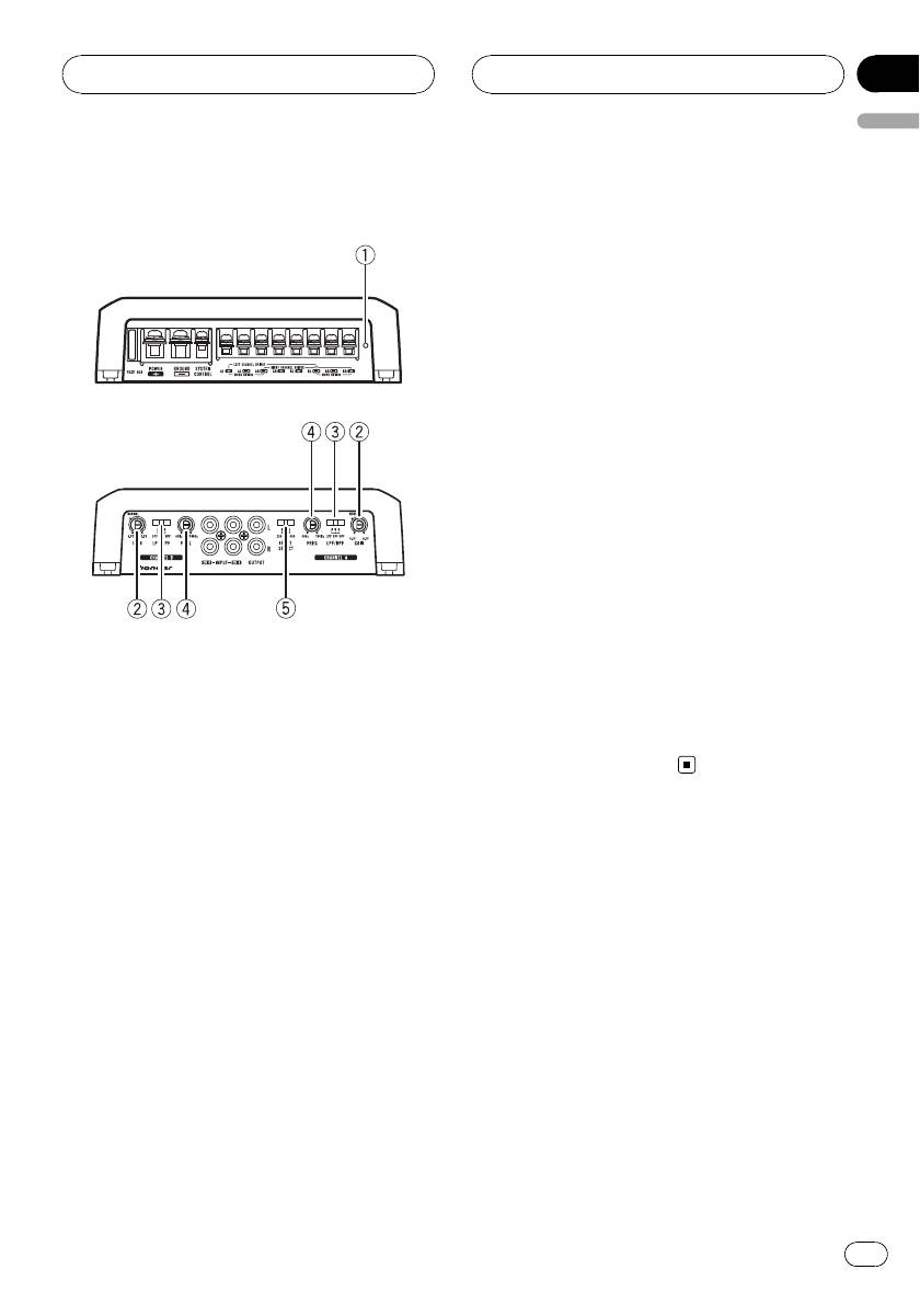
2 GAIN (gain) control
Adjusting gain controls CHANNEL A (chan-
nel A) and CHANNEL B (channel B) helps
Setting gain properly
align the car stereo output to the Pioneer
amplifier. Default setting is the NORMAL
! Protective function included to prevent
position.
malfunction of the unit and/or speakers
If output remains low, even when the car
due to excessive output, improper use or
stereo volume is turned up, turn controls to
improper connection.
lower level. If distortion occurs when the car
! When outputting high volume sound etc.,
stereo volume is turned up, turn these con-
this function cuts off the output for a few
trols to higher level.
seconds as a normal function, but output
! If using only one input plug, set the gain
is restored when the volume of the head
controls for speaker outputs A and B to
unit is turned down.
the same position.
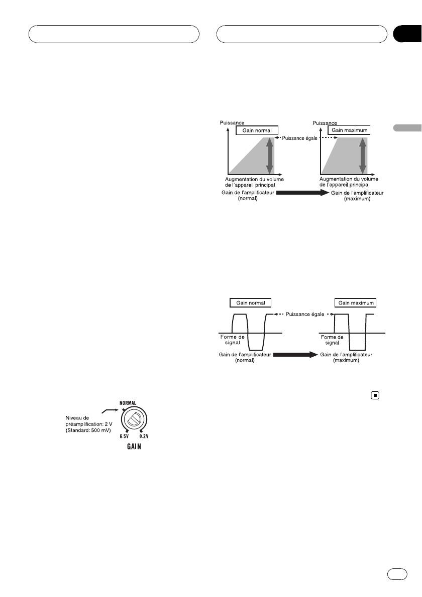
! For use with an RCA equipped car stereo
(standard output of 500 mV), set to the
NORMAL position. For use with an RCA
equipped Pioneer car stereo, with max.
5
En
Section
02
Setting the Unit
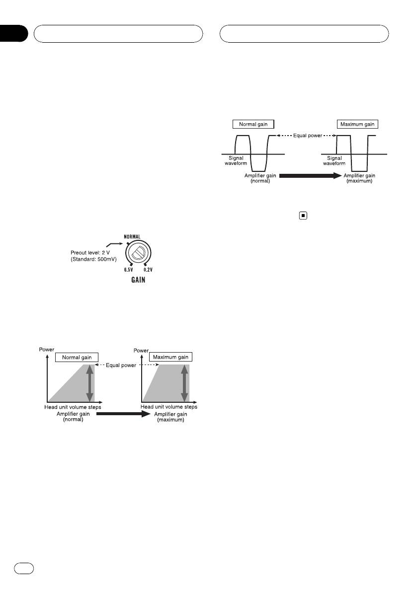
! A cut in sound output may indicate impro-
Signal waveform when outputting at
per setting of the gain control. To ensure
high volume using amplifier gain
continuous sound output with the head
control
unit at a high volume, set amplifier gain
control to a level appropriate for the preout
maximum output level of the head unit, so
that volume can remain unchanged and to
control excess output.
! Despite correct volume and gain settings,
the unit sound still cuts out periodically. In
such cases, please contact the nearest
Signal waveform distorted with high output, if
authorized Pioneer Service Station.
you raise the gain of the amplifier the power
changes only slightly.
Gain control of this unit
Above illustration shows NORMAL gain set-
ting.
Relationship between amplifier gain
and head unit output power
If amplifier gain is raised improperly, this will
simply increase distortion, with little increase
in power.
6
En
Section
Connecting the units
03
English
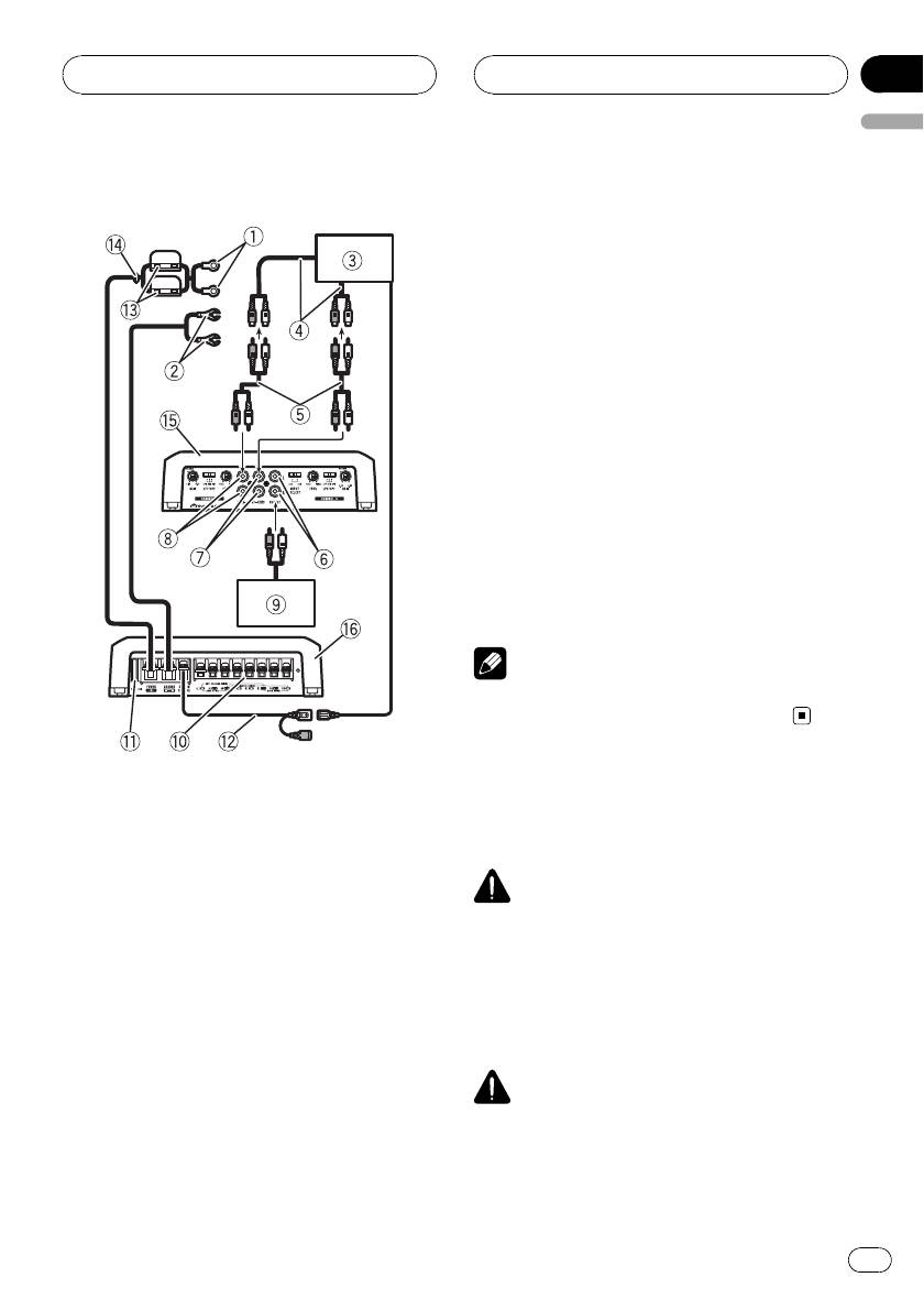
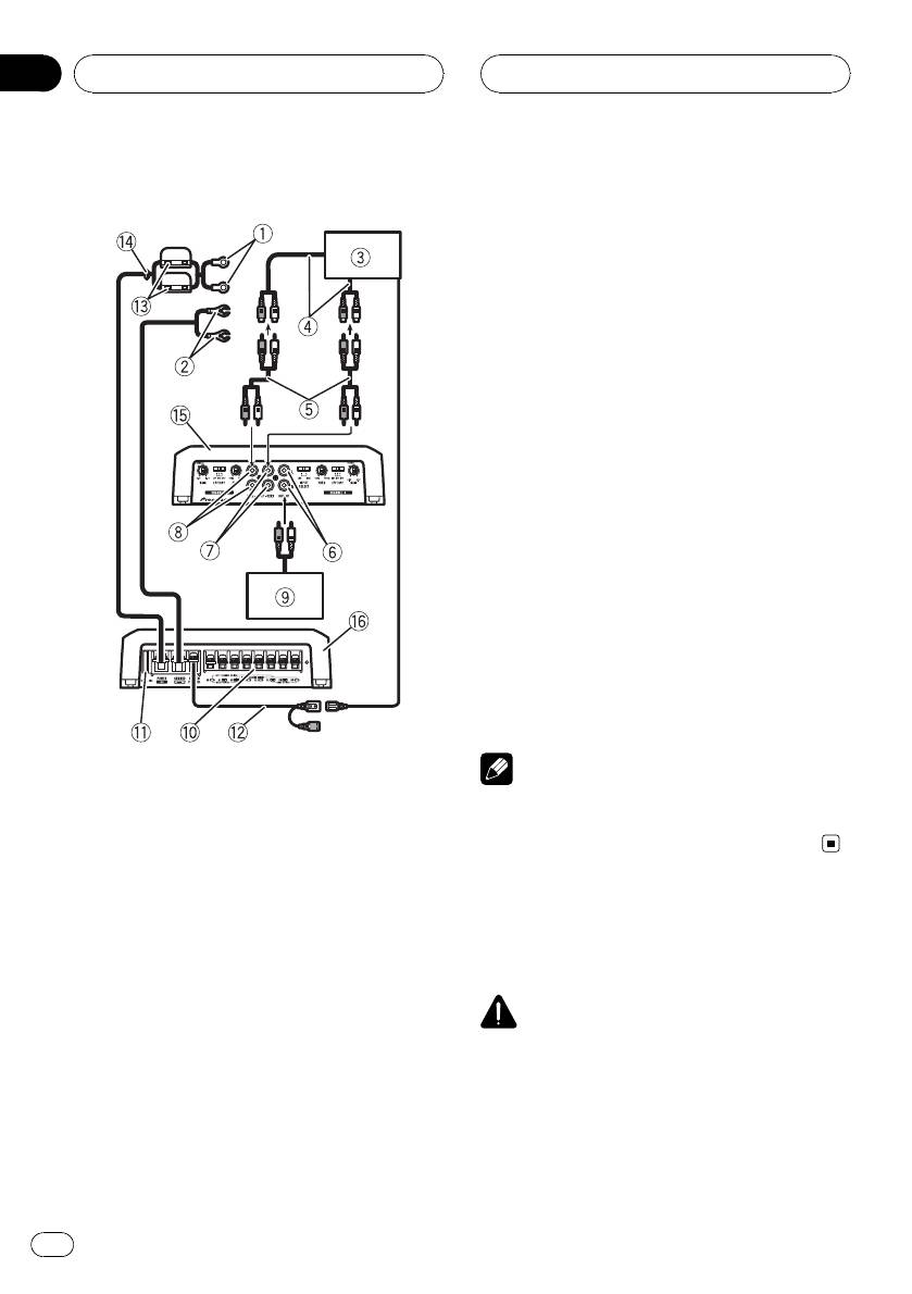
9 Amplifier with RCA input jacks (sold sepa-
Connection diagram
rately)
a Speaker output terminals
Please see the following section for speaker
connection instructions. Refer to Connections
when using the speaker input wire on page 10.
b Fuse (40 A)
c System remote control wire (sold separately)
Connect male terminal of this wire to the sys-
tem remote control terminal of the car stereo.
The female terminal can be connected to the
auto-antenna relay control terminal. If the car
stereo lacks a system remote control terminal,
connect the male terminal to the power term-
inal via the ignition switch.
d Fuse (30 A) × 2
e Grommet
f Rear side
g Front side
Note
INPUT SELECT (input select) switch must be set.
For details, see Setting the Unit on page 5.
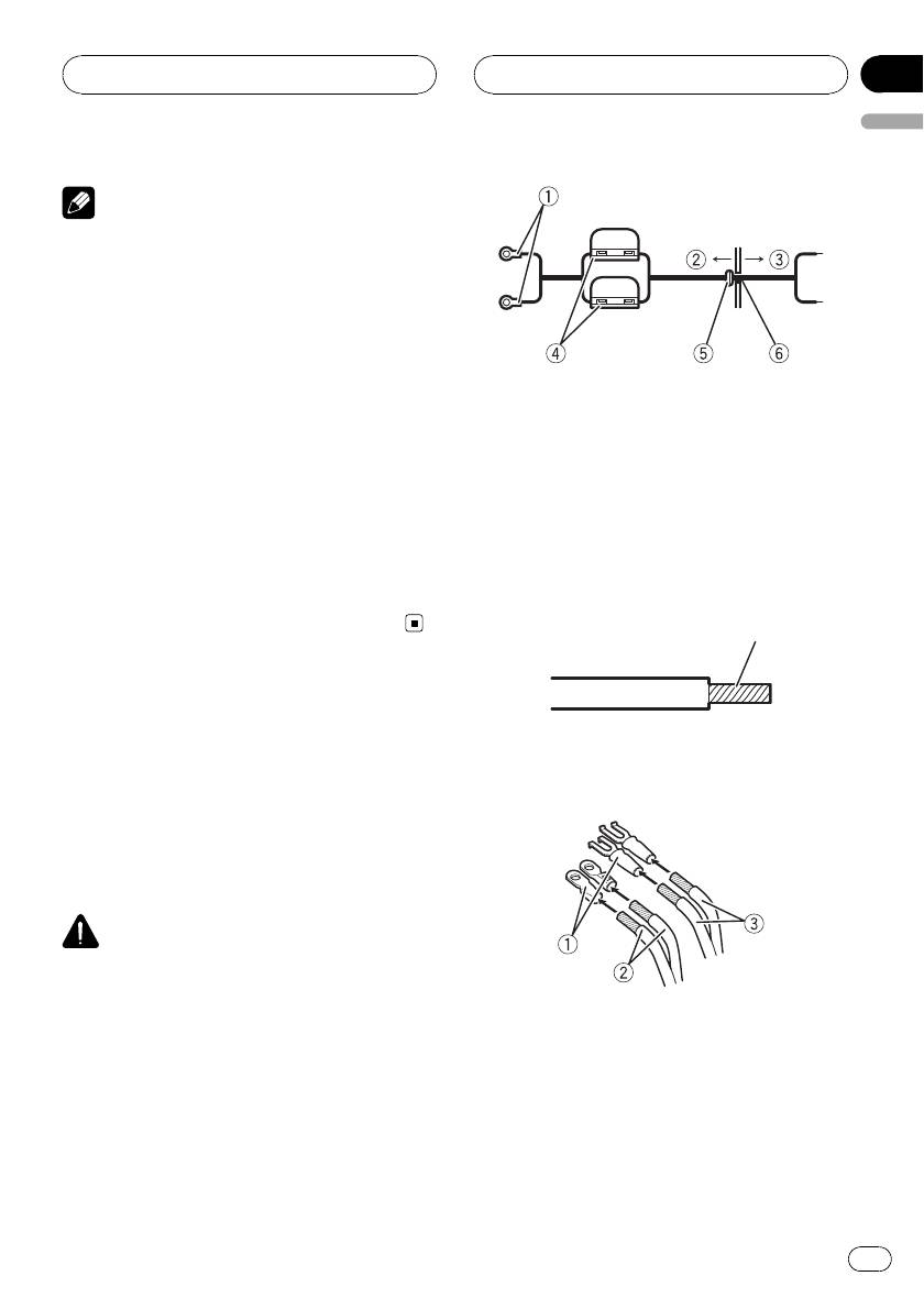
1 Special red battery wire
RD-223 (sold separately)
Before connecting the
After completing all other amplifier connec-
tions, finally connect the battery wire terminal
amplifier
of the amplifier to the positive (+) battery
terminal.
WARNING
2 Ground wire (Black)
! Secure the wiring with cable clamps or adhe-
RD-223 (sold separately)
sive tape. To protect the wiring, wrap sections
Connect to a clean, paint-free metal location.
in contact with metal parts in adhesive tape.
3 Car stereo with RCA output jacks (sold sepa-
! Never cut the insulation of the power supply
rately)
to feed power to other equipment. Current ca-
4 External output
pacity of the wire is limited.
If only one input plug is used, do not connect
anything to RCA input jack B.
5 Connecting wire with RCA pin plugs (sold se-
CAUTION
! Never shorten any wires, the protection circuit
parately)
may malfunction.
6 RCA output jack
! Never wire the speaker negative cable directly-
7 RCA input jack A
to ground.
8 RCA input jack B
7
En
Section
03
Connecting the units
! Never band together multiple speaker’snega-
About suitable
tive cables.
specification of speaker
! If the system remote control wire of the ampli-
fier is connected to the power terminal via the
Ensure speakers conform to the following
ignition switch (12 V DC), the amplifier will re-
standards, otherwise there is a risk of fire,
main on with the ignition whether the car
smoke or damage. Speaker impedance is 2 W
stereo is on or off, which may exhaust battery
to 8 W,or4W to 8 W for two-channel and other
if the engine is at rest or idling.
bridge connections.
! Install and route the separately sold battery
wire as far as possible from the speaker wires.
Subwoofer
Install and route the separately sold battery
Speaker channel Power
wire, ground wire, speaker wires and the am-
plifier as far away as possible from the anten-
Nominal input:
Four-channel output
na, antenna cable and tuner.
Min. 75 W
Nominal input:
Two-channel output
Min. 200 W
Three-channel
Nominal input:
About bridged mode
Speaker output A
Min. 75 W
Three-channel
Nominal input:
Speaker output B
Min. 200 W
Other than subwoofer
Speaker channel Power
Max. input:
Four-channel output
Min. 150 W
Max. input:
Two-channel output
Min. 400 W
Three-channel
Max. input:
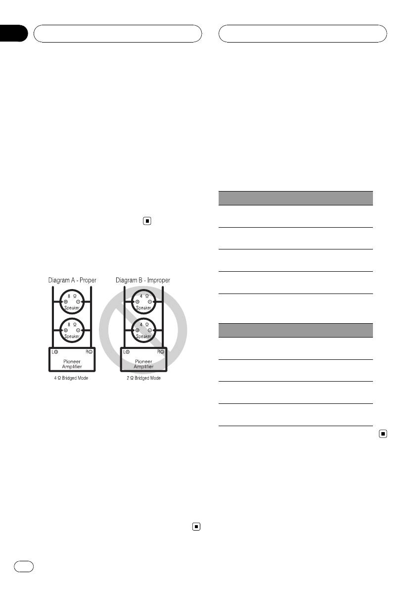
Speaker impedance is max. 4 W, please carefully
Speaker output A
Min. 150 W
check. Improper connection to the amplifier may
Three-channel
Max. input:
result in malfunction or personal injury due to
Speaker output B
Min. 400 W
burns from overheating.
For bridged mode for a two-channel amplifier,
with a 4 W load, either wire two 8 W speakers in
parallel, Left + and Right * (Diagram A) or use a
single 4 W speaker. For other amplifiers, please
follow the speaker output connection diagram for
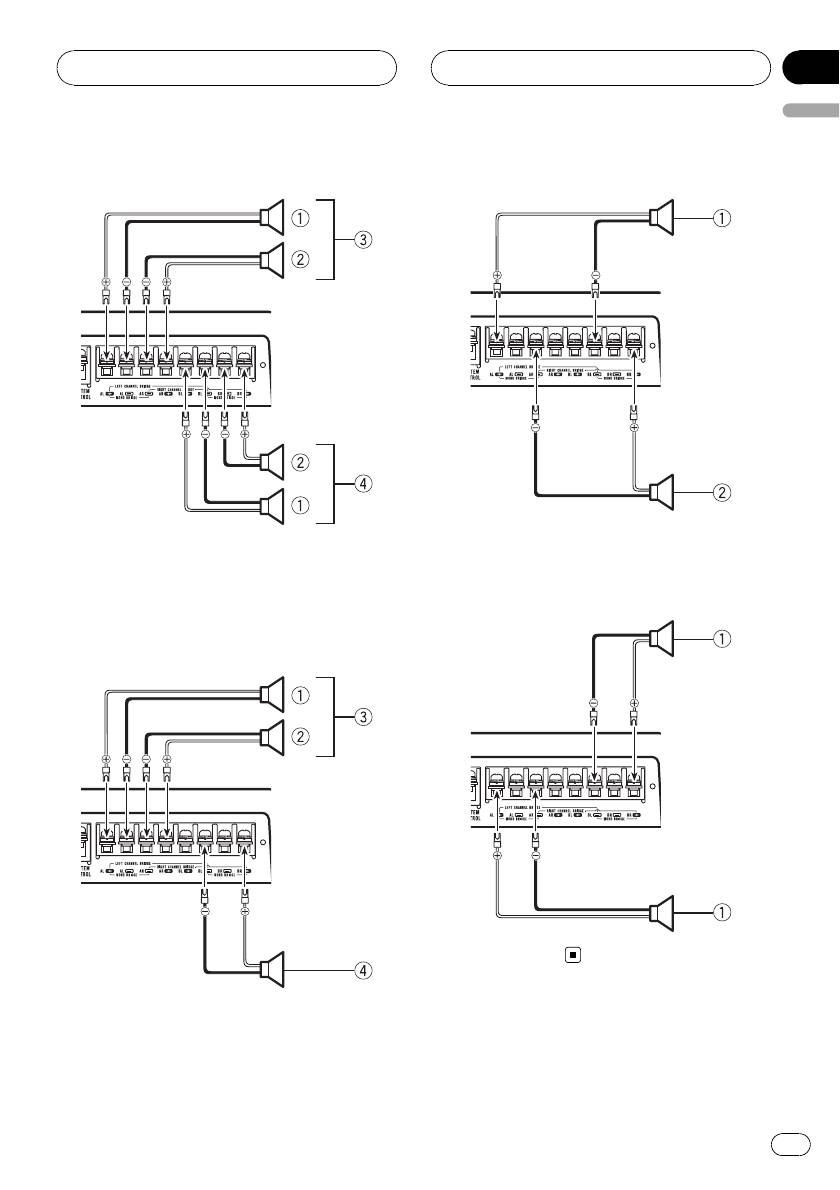
Connecting the speakers
bridging shown on rear: two 8 W speakers in par-
The speaker output mode can be four-channel,
allel for a 4 W load or a single 4 W speaker per
three-channel (stereo and mono) or two-chan-
channel.
nel (stereo or mono). Connect the speaker
For any further enquiries, contact your local
leads based on the mode and the figures
authorized Pioneer dealer or customer service.
shown below.
8
En
Section
Connecting the units
03
English
Four-channel output
Two-channel output (Stereo)
1 Speaker (Left)
1 Left
2 Speaker (Right)
2 Right
3 Speaker out A
Two-channel output (Mono)
4 Speaker out B
Three-channel output
1 Speaker (Mono)
1 Left
2 Right
3 Speaker out A
4 Speaker out B (Mono)
9
En
Section
03
Connecting the units
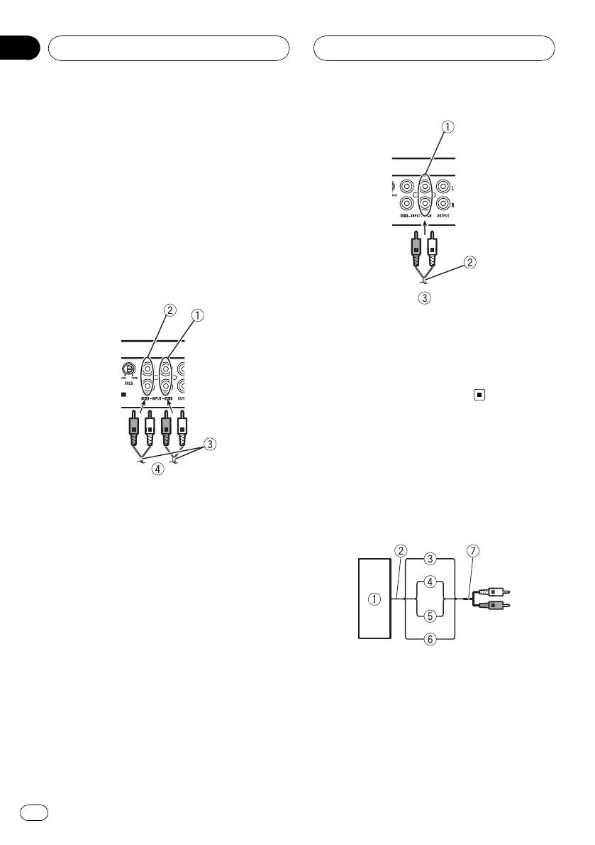
Connections when using
the RCA input jack
Connect the car stereo RCA output jack and
the RCA input jack of the amplifier.
! The RCA output jack of this unit outputs
the signal that comes from The RCA input
jack A.
Four-channel / Three-channel output
! Slide INPUT SELECT (input select) switch
to 4CH position.
1 RCA input jack A
For two-channel output, connect the RCA
plugs to the RCA input jack A.
2 Connecting wire with RCA pin plugs (sold se-
parately)
3 From car stereo (RCA output)
Connections when using
the speaker input wire
1 RCA input jack A
Connect the car stereo speaker output wires
2 RCA input jack B
to the amplifier using the supplied speaker
3 Connecting wires with RCA plugs (sold sepa-
input wire with RCA pin cord.
rately)
4 From car stereo (RCA output)
If only one input plug is used, e.g. when the
car stereo has only one output (RCA output),
connect the plug to RCA input jack A rather
than B.
Two-channel output (Stereo) / (Mono)
! Slide INPUT SELECT (input select) switch
1 Car Stereo
to 2CH position.
2 Speaker output
3 Red: Right +
4 Black: Right *
5 Black: Left *
6 White: Left +
7 Speaker input wire with RCA pin cord
To the RCA input jack of this unit
10
En
Section
Connecting the units
03
English
Note
! If speaker wires with an RCA pin cord from a
headunit are connected to this amplifier, the
amplifier will automatically turn on when the
headunit is turned on. When the headunit is
turned off, the amplifier turns off automati-
cally. This function may not work with some
headunits. In such cases, please use a sys-
1 Positive (+) terminal
tem remote control wire (sold separately). If
2 Engine compartment
multiple amplifiers are to be connected to-
3 Vehicle interior
gether synchronously, connect the head unit
4 Fuse (30 A) × 2
and all amplifiers via the system remote con-
5 Insert the O-ring rubber grommet into the
trol wire.
vehicle body.
! Connect the system remote control wire when
6 Drill a 14 mm hole into the vehicle body.
you wish to only turn on the car stereo, not the
amplifier.
2 Twist the battery wire, ground wire
! This amplifier automatically selects an input
and system remote control wire.
signal mode between the RCA level and the
speaker level by detecting an input signal.
Twist
Connecting the power
terminal
3 Attach lugs to wire ends. Lugs not sup-
plied.
! The use of a special red battery and ground
Use pliers, etc., to crimp lugs to wires.
wire RD-223, available separately, is recom-
mended. Connect the battery wire directly
to the car battery positive terminal (+) and
the ground wire to the car body.
WARNING
If the battery wire is not securely fixed to the term-
inal using the terminal screws, there is a risk of
overheating, malfunction and injury, including
1 Lug
minor burns.
2 Battery wire
3 Ground wire
1 Route battery wire from engine com-
partment to the vehicle interior.
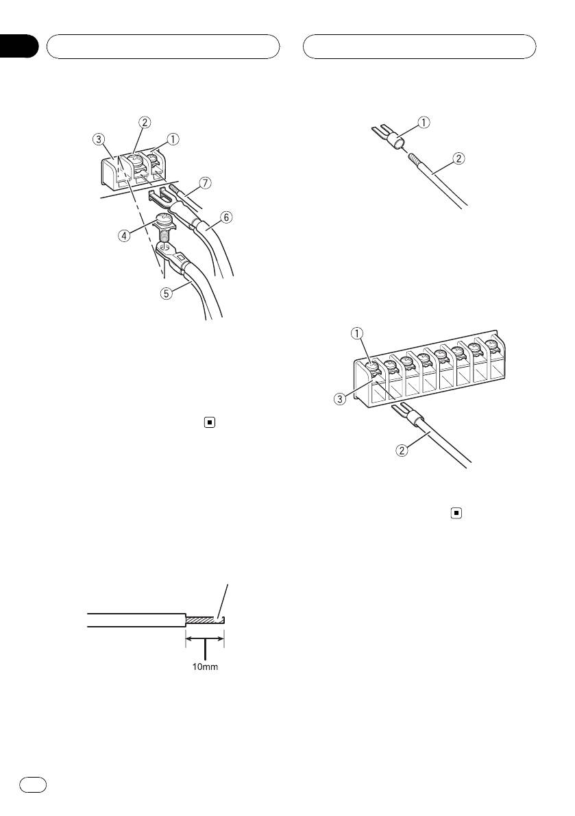
4 Connect the wires to the terminal.
After completing all other amplifier connec-
Fix the wires securely with the terminal
tions, finally connect the battery wire terminal
screws.
of the amplifier to the positive (+) battery
terminal.
11
En
Section
03
Connecting the units
1 Lug
2 Speaker wire
3 Connect the speaker wires to the
speaker output terminals.
Fix the speaker wires securely with the term-
inal screws.
1 System remote control terminal
2 GND terminal
3 Power terminal
4 Terminal screws
5 Battery wire
6 Ground wire
7 System remote control wire
Connecting the speaker
1 Terminal screws
2 Speaker wires
output terminals
3 Speaker output terminals
1 Expose the end of the speaker wires
using nippers or a cutter by about 10 mm
and twist.
Twist
2 Attach lugs to speaker wire ends. Lugs
not supplied.
Use pliers, etc., to crimp lugs to wires.
12
En
Section
Installation
04
English
Before installing the amplifier
Example of installation on
the floor mat or chassis
WARNING
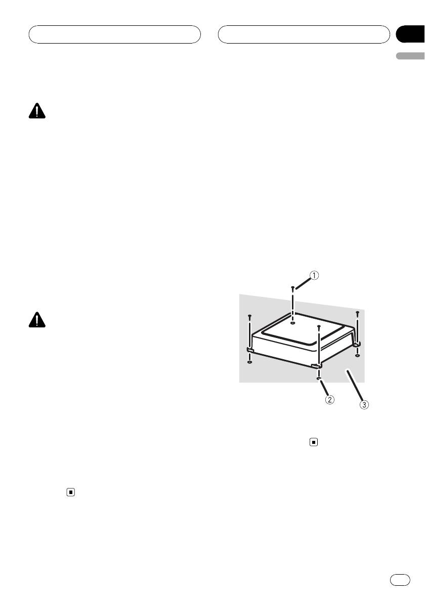
1 Place the amplifier in the desired instal-
! Do not use unauthorized parts as this may
lation location.
cause malfunctions.
Insert the supplied tapping screws (4 mm ×
! Do not install this unit where :
18 mm) into the screw holes and push on the
— it may interfere with operation of the vehi-
screws with a screwdriver so they make an im-
cle.
print where the installation holes are to be lo-
— it may cause injury to a passenger as a re-
cated.
sult of a sudden stop.
! Install tapping screws in such a way that the
2 Drill 2.5 mm diameter holes at the im-
screw tip does not touch any wire. This is im-
prints either on the carpet or directly on
portant to prevent wires from being cut by vi-
the chassis.
bration of the car, which can result in fire.
! Place all cables away from moving parts, such
3 Install the amplifier with the use of
as the gear shift and seat rails.
supplied tapping screws (4 mm × 18 mm).
! When drilling to install the amplifier, always
confirm no parts are behind the panel and
protect all cables and important equipment
(e.g. fuel/brake lines, wiring) from damage.
CAUTION
! To ensure proper heat dissipation of the ampli-
fier, ensure the following during installation:
— Allow adequate space above the amplifier
for proper ventilation.
— Do not cover the amplifier with a floor mat
or carpet.
! Place all cables away from hot places, such
as near the heater outlet.
! The optimal installation location differs de-
1 Tapping-screws (4 mm × 18 mm)
pending on the car model. Secure the ampli-
2 Drill a 2.5 mm diameter hole
fier at a sufficiently rigid location.
3 Floor mat or chassis
! Check all connections and systems before
final installation.
! After installing the amplifier, confirm that the
spare tire, jack and tools can be easily re-
moved.
13
En

Appendix
Additional information
audio signal is input. Use this value when
Specifications
working out total current drawn by multiple
Power source ............................. 14.4 V DC (10.8 V to 15.1 V
power amplifiers.
allowable)
Grounding system ................... Negative type
Current consumption ............ 25 A (at continuous power,
4 W)
Average current drawn ......... 7.9 A (4 W for four channels)
10.5 A (4 W for two chan-
nels)
10.7 A (2 W for four chan-
nels)
Fuse ................................................ 40 A × 1
Dimensions (W × H × D) ... 245 mm × 56 mm × 200
mm
Weight .......................................... 2.2 kg (Leads for wiring not
included)
Maximum power output ....... 150 W × 4 (4 W)/400W×2
(4 W)
Continuous power output ... 75 W × 4 (at 14.4 V, 4 W,20
Hz to 20 kHz, ≦ 1% THD)
200 W × 2 (at 14.4 V, 4 W
BRIDGE, 1 kHz, ≦ 1% THD)
100 W × 4 (at 14.4 V, 2 W,1
kHz, ≦ 1% THD)
Load impedance ...................... 4 W (2 W to 8 W allowable)
(Bridge connection: 4 W to 8
W allowable)
Frequency response ............... 10 Hz to 35 kHz (+0 dB, -3
dB)
Signal-to-noise ratio ............... 95 dB (IEC-A network)
Distortion ..................................... 0.06 % (10 W, 1 kHz)
Separation .................................. 67 dB (1 kHz)
60 dB (100 Hz to 10 kHz)
Low pass filter:
Cut off frequency ........... 40 Hz to 500 Hz
Cut off slope ..................... -12 dB/oct
High pass filter:
Cut off frequency ........... 40 Hz to 500 Hz
Cut off slope ..................... -12 dB/oct
Gain control:
RCA ...................................... 200 mV to 6.5 V
Speaker .............................. 0.8 V to 10 V
Maximum input level / impedance:
RCA ...................................... 6.5 V / 22 kW
Speaker .............................. 10 V / 22 kW
Notes
! Specifications and the design are subject to
modifications without notice.
! The average current drawn is nearly the maxi-
mum current drawn by this unit when an
14
En

Table des matières
Nous vous remercions d ’avoir acheté cet appareil
PIONEER.
Pour garantir une utilisation correcte, lisez bien ce mode d’emploi avant d’utiliser
cet appareil. Conse rvez-le dans un endroit sûr et facilement accessible pour toute
consultation ultérieure.
Français
Avant de commencer
En cas d’anomalie 16
Avant de connecter/d’installer
l’amplificateur 16
Réglage de l’appareil
Description de l’appareil 18
Réglage correct du gain 19
Connexion des appareils
Schéma de connexion 20
Avant de connecter l’amplificateur 20
À propos du mode ponté 21
À propos de la spécification adaptée des
haut-parleurs 21
Connexion des haut-parleurs 22
Connexions lors de l’utilisation du jack
d’entrée RCA 23
Connexions lors de l’utilisation du fil d’entrée
des haut-parleurs 24
Connexion de la borne d’alimentation 24
Connexion des bornes de sortie des haut-
parleurs 26
Installation
Avant d’installer l’amplificateur 27
Exemple d’installation sur le tapis de sol ou
le châssis 27
Informations complémentaires
Caractéristiques techniques 28
15
Fr
Section
01
Avant de commencer
Avant de connecter/
d’installer l’amplificateur
ATTENTION
! L’utilisation d’un fil de terre RD-223 et d’un fil
de batterie rouge spécial, disponibles séparé-
Si vous souhaitez vous débarrasser de cet ap-
ment, est recommandée. Connectez le fil de la
pareil, ne le mettez pas à la poubelle avec vos
batterie directement sur la borne positive +
ordures ménagères. Il existe un système de
de la batterie du véhicule et le fil de terre sur
collecte séparé pour les appareils électroni-
la carrosserie du véhicule.
ques usagés, qui doivent être récupérés, traités
! Cet appareil est utilisable sur des véhicules
et recyclés conformément à la législation.
équipés d’une batterie 12V avec mise à la
masse du négatif. Vérifiez la tension de la bat-
Dans les états membres de l’UE, en Suisse et
terie avant l’installation dans des véhicules de
en Norvège, les foyers domestiques peuvent
caravaning, des camions ou des bus.
rapporter leurs produits électroniques usagés
! Le câble noir est la masse. Lors de l’installa-
gratuitement à des points de collecte spécifiés
tion de cet appareil, veillez à connecter d’a-
ou à un revendeur (sous réserve d’achat d’un
bord le fil de masse. Assurez-vous que le fil de
produit similaire).
masse est connecté correctement aux parties
Dans les pays qui ne sont pas mentionnés ci-
métalliques de la carrosserie du véhicule. Le
dessus, veuillez contacter les autorités locales
fil de masse de cet appareil doit être connecté
pour vous informer de la méthode correcte de
indépendamment au véhicule à l’aide de vis
mise au rebut.
différentes. Si la vis du fil de masse se des-
En agissant ainsi vous assurerez que le pro-
serre ou tombe, il peut en résulter un incen-
duit que vous mettez au rebut est soumis au
die, de la fumée ou un dysfonctionnement.
processus de traitement, de récupération et
! Utilisez un fusible correspondant aux caracté-
de recyclage nécessaire et éviterez ainsi les ef-
ristiques spécifiées.
fets négatifs potentiels sur l’environnement et
! Vérifiez les connexions de l’alimentation et
la santé publique.
des haut-parleurs en cas de rupture du fusible
du fil de batterie vendu séparément ou de
l’amplificateur. Déterminez la cause et résol-
vez le problème, puis remplacez le fusible par
En cas d’anomalie
un fusible identique.
! Installez toujours l’amplificateur sur une sur-
En cas d’anomalie, consultez le distributeur
face plane. N’installez pas l’amplificateur sur
ou le service d’entretien agréé par Pioneer le
une surface qui n’est pas plane ou sur une
plus proche.
sur face présentant une saillie. Ceci pourrait
entraîner un dysfonctionnement.
! Lors de l’installation de l’amplificateur, ne lais-
sez pas des pièces telles que des vis supplé-
mentaires se coincer entre l’amplificateur et
l’automobile. Ceci pourrait entraîner un dys-
fonctionnement.
16
Fr
Section
Avant de commencer
01
! Ne laissez pas cet appareil entrer en contact
avec des liquides. Cela pourrait provoquer une
électrocution. Tout contact avec des liquides
pourrait aussi provoquer des dommages, de
la fumée et une surchauffe de l’appareil.
Français
Les surfaces de l’amplificateur et des haut-
parleurs connectés peuvent également chauf-
fer et entraîner des brûlures mineures.
! En cas d’événement anormal, l’alimentation
de l’amplificateur est coupée de manière à évi-
ter tout dysfonctionnement de l’équipement.
Dans ce cas, coupez l’alimentation du sys-
tème et vérifiez les connexions de l’alimenta-
tion et des haut-parleurs. Si vous n’êtes pas
en mesure de déterminer la cause, veuillez
contacter votre revendeur.
! Déconnectez la borne négative de la batterie
avant l’installation.
PRÉCAUTION
! Maintenez le niveau d’écoute à une valeur
telle que vous puissiez entendre les sons pro-
venant de l’extérieur.
! L’utilisation prolongée du système stéréo du
véhicule lorsque le moteur est à l’arrêt ou au
ralenti peut épuiser la batterie.
17
Fr
Section
02
Réglage de l’appareil
! Procédez au réglage sur la position
Description de l’appareil
NORMAL pour l’utilisation avec un sys-
Face avant
tème stéréo de véhicule équipé d’une
sortie RCA (sortie standard de 500 mV).
Pour l’utilisation avec un système stéréo
de véhicule Pioneer équipé d’une sortie
RCA, dont la sortie maximale est de 4 V
ou plus, réglez le niveau en fonction de
celui de sortie du système stéréo du véhi-
cule.
Face arrière
3 Commutateur de sélection LPF (filtre
passe-bas)/HPF (filtre passe-haut)
Basculez les réglages en fonction du haut-
parleur connecté.
! Lorsque le haut-parleur d’extrêmes gra-
ves est connecté :
Sélectionnez LPF. Cela supprime les fré-
quences élevées et émet à basse fré-
quence.
Si nécessaire, utilisez un tournevis plat pour
! Lorsque le haut-parleur pleine gamme
régler le commutateur.
est connecté :
Sélectionnez HPF ou OFF. HPF supprime
1 Indicateur de mise sous tension
les basses fréquences et émet à haute
L’indicateur de mise sous tension s’allume
fréquence. OFF émet la gamme de fré-
pour indiquer la mise sous tension.
quences complète.
2 Commande GAIN (gain)
4 Commande FREQ (fréquence de cou-
Le réglage des commandes de gain
pure)
CHANNEL A (canal A) et CHANNEL B
La fréquence de coupure pouvant être sélec-
(canal B) aide à aligner la sortie stéréo du
tionnée est de 40 Hz à 500 Hz si le commu-
véhicule sur l’amplificateur Pioneer. Le ré-
tateur de sélection LPF/HPF est réglé sur
glage par défaut est la position NORMAL.
LPF ou HPF.
Si la sortie reste faible alors que le volume
du système stéréo du véhicule a été aug-
5 Commutateur INPUT SELECT (sélection
menté, tournez les commandes vers un ni-
de l’entrée)
veau plus faible. En cas de distorsion lors
Sélectionnez 2CH pour l’entrée deux canaux
de l’augmentation du volume du système
et 4CH pour l’entrée quatre canaux.
stéréo du véhicule, tournez les commandes
vers un niveau plus élevé.
! Si vous n’utilisez qu’une seule prise d’en-
trée, réglez les commandes de gain des
sorties de haut-parleurs A et B sur la
même position.
18
Fr
Section
Réglage de l’appareil
02
Relation entre le gain de
Réglage correct du gain
l’amplificateur et la puissance de
! Fonction de protection incluse pour éviter
sortie de l’appareil central
tout dysfonctionnement de l’appareil et/ou
des haut-parleurs lié à une sortie excessive
Français
ou à une utilisation ou une connexion in-
correcte.
! Lors de l’émission de sons à haut volume,
etc., cette fonction coupe l’émission pen-
dant quelques secondes. L’émission est ce-
pendant rétablie une fois le volume de
l’appareil central baissé.
! Une coupure de la sortie son peut indiquer
Si le gain de l’amplificateur est augmenté de
un réglage incorrect de la commande de
manière incorrecte, les distorsions augmen-
gain. Afin de garantir une émission sonore
tent sans que la puissance soit beaucoup plus
continue lorsque le volume de l’appareil
importante.
central est élevé, réglez la commande de
gain de l’amplificateur à un niveau adapté
Forme de signal lors de l’émission à
au niveau de sortie maximal de la sortie
volume élevé avec la commande de
préamp de l’appareil central de manière à
gain de l’amplificateur
ce que le volume ne nécessite aucune mo-
dification et à ce que les sorties excessives
soient contrôlées.
! Le son de l’appareil est régulièrement
coupé alors que les réglages du gain et du
volume sont corrects. Dans de tels cas,
veuillez contacter le Centre d’entretien
agréé par Pioneer le plus proche.
Forme de signal distordu avec sortie élevée, si
vous augmentez le gain de l’amplificateur, la
Commande de gain de l’appareil
puissance n’est que légèrement modifiée.
L’illustration ci-dessus représente le réglage
de gain NORMAL.
19
Fr
Section
03
Connexion des appareils
8 Jack d’entrée RCA B
Schéma de connexion
9 Amplificateur avec jacks d’entrée RCA (vendu
séparément)
a Bornes de sortie des haut-parleurs
Veuillez vous reporter à la section suivante
pour les instructions de connexion des haut-
parleurs. Reportez-vous à la page 24, Conne-
xions lors de l’utilisation du fil d’entrée des
haut-parleurs.
b Fusible (40 A)
c Fil de la télécommande du système (vendu sé-
parément)
Connectez la borne mâle du fil à la borne de
la télécommande du système stéréo du véhi-
cule. La borne femelle peut être connectée à
la prise de commande du relais de l’antenne
motorisée. Si le système stéréo du véhicule ne
dispose pas d’une borne de télécommande,
connectez la borne mâle à la borne d’alimen-
tation via le contact d’allumage.
d Fusible (30 A) × 2
e Rondelle
f Face arrière
g Face avant
1 Fil de batterie rouge spécial
Remarque
RD-223 (vendu séparément)
Le commutateur INPUT SELECT (sélection de
Une fois toutes les autres connexions de l’am-
l’entrée) doit être réglé. Pour plus de détails, re-
plificateur effectuées, connectez la borne du
portez-vous à la page 18, Réglage de l’appareil.
fil de batterie de l’amplificateur à la borne po-
sitive (+) de la batterie.
2 Fil de terre (noir)
RD-223 (vendu séparément)
Avant de connecter
Connectez sur un endroit métallique propre,
non recouvert de peinture.
l’amplificateur
3 Système stéréo de véhicule avec jacks de sor-
tie RCA (vendu séparément)
ATTENTION
4 Sortie externe
! Fixez le câblage avec des serre-fils ou de la
Si une seule prise d’entrée est utilisée, ne
bande adhésive. Pour protéger le câblage, en-
connectez rien au jack d’entrée RCA B.
roulez les sections en contact avec des pièces
5 Fil de connexion avec prises RCA (vendu sépa-
en métal dans du ruban adhésif.
rément)
! Ne découpez jamais l’isolation de l’alimenta-
6 Jack de sortie RCA
tion pour alimenter d’autres équipements. La
7 Jack d’entrée RCA A
capacité en courant du fil est limitée.
20
Fr


