Pioneer DEH-P8100BT: инструкция
Раздел: Авто, мото оборудование и транспорт
Тип: Автомагнитола
Инструкция к Автомагнитоле Pioneer DEH-P8100BT
Оглавление
- Содержание Подключение устройств
- Подключение устройств
- Подключение устройств Соединительный шнур питания
- Подключение устройств
- Подключение устройств Соединение с усилителем мощности, который продается отдельно
- Подключение устройств
- Установка Переднее/Заднее крепление по стандарту DIN
- Установка Установка микрофона
- Установка Когда микрофон установлен Установка Устройства на рулевой колонке Дистанционного Управления на Руле Регулировка угла наклона микрофона
- Установка Установка устройства на автомобилях с левым рулевым управлением колес

English
CD RDS RECEIVER
REPRODUCTOR DE CD CON RECEPTOR RDS
Español Deutsch
CD RDS-EMPFÄNGER
AUTORADIO CD RDS
SINTOLETTORE CD RDS
CD RDS-ONTVANGER
CD RDS ПРИЕМНИК
DEH-P8100BT
Français
Italiano
Nederlands
Installation Manual
Manual de instalación
Installationsanleitung
Manuel d’installation
Русский
Manuale d’installazione
Installatiehandleiding
Руководство по установке
Contents Connecting the units
Connecting the units ............................ 2
Note
Connecting the power cord
...............................
4
When connecting to
• When this unit is installed in a vehicle without
separately sold power amp ........................ 6
ACC (accessory) position on the ignition switch,
red cable must be wired to the terminal that can
Installation ............................................. 8
detect the operation of the ignition key. Otherwise,
DIN Front/Rear-mount ..................................... 8
battery drain may result.
Removing or attaching the trim ring ...................... 8
DIN Front-mount ...................................................... 8
C
A
C
O
O
F
N
F
N
DIN Rear-mount ....................................................... 9
F
F
O
O
S
S
Installing the microphone ............................... 9
T
T
A
A
R
R
When installing the microphone
T
T
on the sun visor ................................................... 9
When installing the microphone
on the steering column ..................................... 10
ACC position
No ACC position
Adjusting the microphone angle .......................... 10
Installing the steering remote control ......... 10
• Use this unit in other than the following
Installing the unit on a left-hand drive car ........... 11
conditions could result in fire or malfunction.
— Vehicles with a 12-volt battery and negative
grounding.
— Speakers with 50 W (output value) and 4 ohm
to 8 ohm (impedance value).
• To prevent short-circuit, overheating or
malfunction, be sure to follow the directions
below.
— Disconnect the negative terminal of the
battery before installation.
— Secure the wiring with cable clamps or
adhesive tape. To protect the wiring, wrap
adhesive tape around them where they lie
against metal parts.
— Place all cables away from moving parts, such
as gear shift and seat rails.
— Place all cables away from hot places, such as
near the heater outlet.
— Do not pass the yellow cable through a hole
into the engine compartment to connect to a
battery.
— Cover any disconnected cable connectors with
insulating tape.
— Do not shorten any cables.
— Never cut the insulation of the power cable of
this unit in order to share the power to other
equipment. Current capacity of the cable is
limited.
— Use a fuse of the rating prescribed.
— Never wire the speaker negative cable directly
to ground.
— Never band together multiple speaker’s
negative cables.
2

Connecting the units
English
• Control signal is output through blue/white cable
when this unit is powered on. Connect it to an
external power amp’s system remote control or
the vehicle’s auto-antenna relay control terminal
(max. 300 mA, 12 V DC). If the vehicle is equipped
with a glass antenna, connect it to the antenna
booster power supply terminal.
• Never connect blue/white cable to external power
amp’s power terminal. Also, never connect
it to the power terminal of the auto antenna.
Otherwise, battery drain or malfunction may
result.
• IP-BUS connectors are color-coded. Be sure to
connect connectors of the same color.
• Black cable is ground. This cable and other
product’s ground cable (especially, high-current
products such as power amp) must be wired
separately. Otherwise, fire or malfunction may
result if they are accidentally detached.
3
Connecting the units
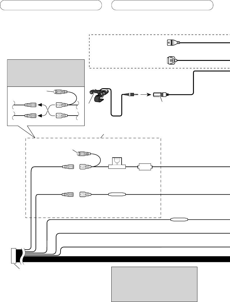
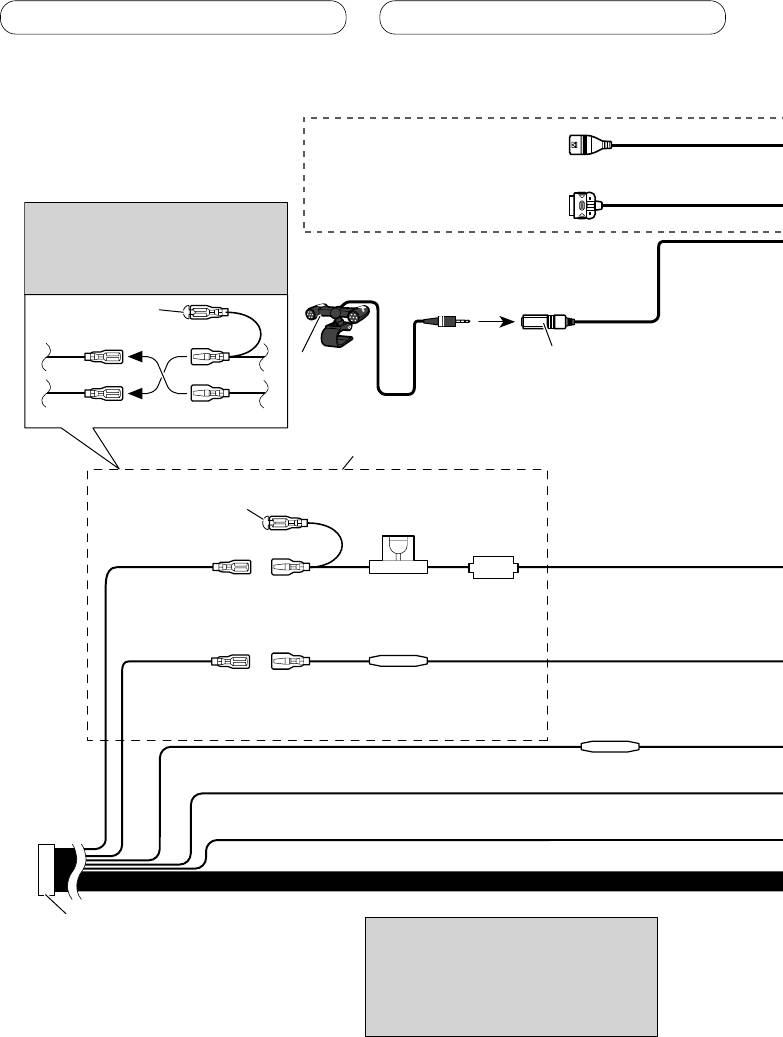
Connecting the power cord
USB cable
Use supplied USB cable or separately
sold USB cable (CD-U150E).
iPod to USB connection cable
Use separately sold iPod to USB
Note
connection cable (CD-IU50).
Depending on the kind of vehicle,
the function of 3* and 5* may be
different. In this case, be sure to
connect 2* to 5* and 4* to 3*.
1*
15 cm
3* 2*
Microphone input
Microphone
4 m
4*5*
Connect leads of the same
color to each other.
Cap (1*)
Do not remove cap if
this terminal is not in
Fuse (10 A)
use.
Yellow (3*)
Yellow (2*)
Back-up (or
Connect to the constant 12 V
accessory)
supply terminal.
Fuse resister
Red (5*)
Red (4*)
Accessory (or
Connect to terminal controlled by
back-up)
ignition switch (12 V DC).
Fuse resister
Orange/white
Connect to lighting switch terminal.
Black (chassis ground)
Connect to a clean, paint-free metal location.
ISO connector
Note
Note
When using a subwoofer of 70 W (2
In some vehicles, the ISO connector may
Ω), be sure to connect with Violet
be divided into two. In this case, be sure to
and Violet/black leads of this unit.
connect to both connectors.
Do not connect anything with Green
and Green/black leads.
4
Connecting the units
English
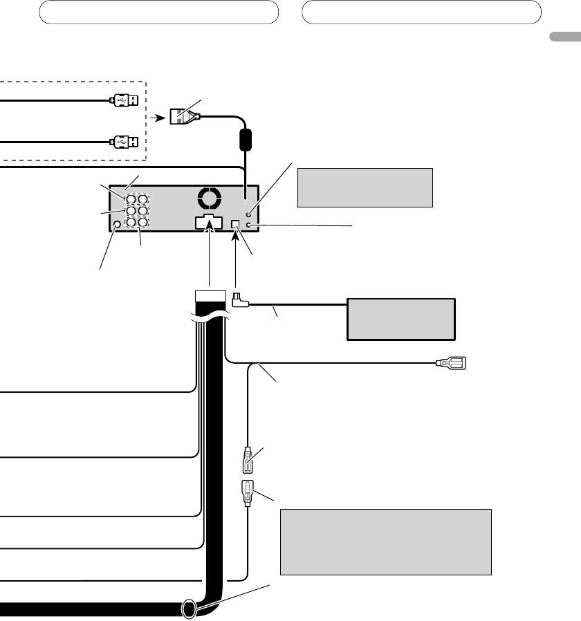
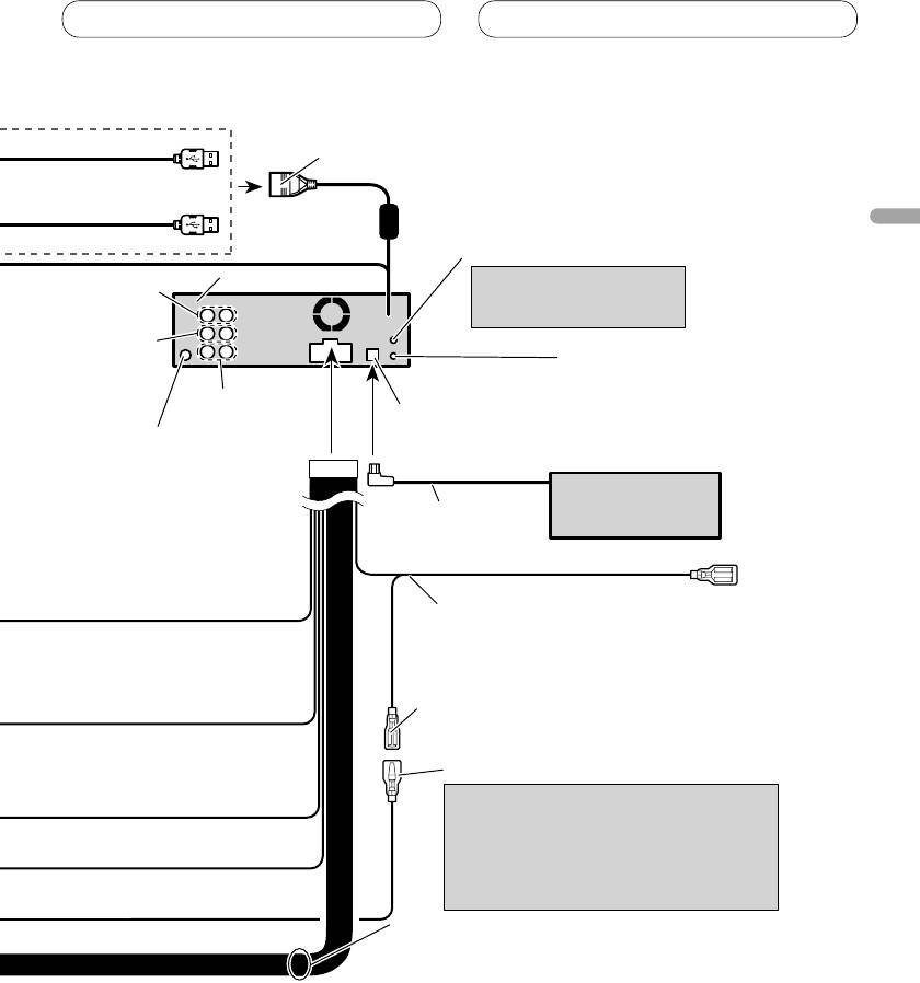
1.5 m
USB1/USB2 input jack
20 cm
50 cm
AUX jack (3.5 φ)
Use a stereo mini plug cable
This product
Rear output
to connect with auxiliary
device.
Front output
Wired remote input
Hard-wired remote control
adaptor can be connected
Subwoofer output
(sold separately).
IP-BUS input (Blue)
Antenna jack
Multi-CD player
(sold separately)
IP-BUS cable
Blue/white
Connect to system control terminal of the
power amp (max. 300 mA 12 V DC).
Blue/white (7*)
Connect to auto-antenna relay control
terminal (max. 300 mA 12 V DC).
Blue/white (6*)
The pin position of the ISO connector will
differ depends on the type of vehicle.
Connect 6* and 7* when Pin 5 is an
antenna control type. In another type of
vehicle, never connect 6* and 7*.
Speaker leads
White: Front left
White/black: Front left
Gray: Front right
Gray/black: Front right
Green: Rear left or subwoofer
Green/black: Rear left or subwoofer
Violet: Rear right or subwoofer
Violet/black: Rear right or subwoofer
5
Connecting the units
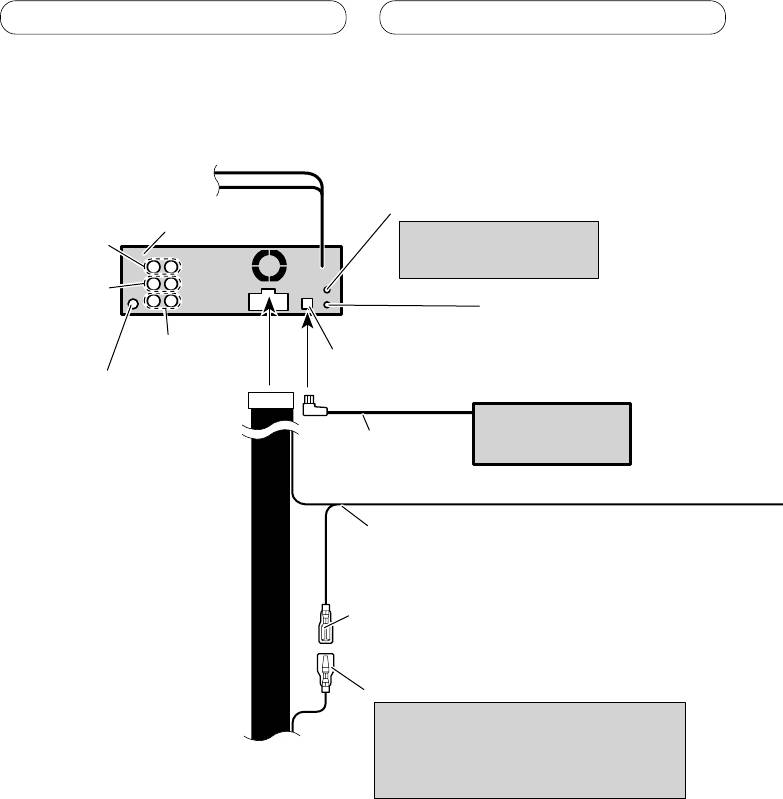
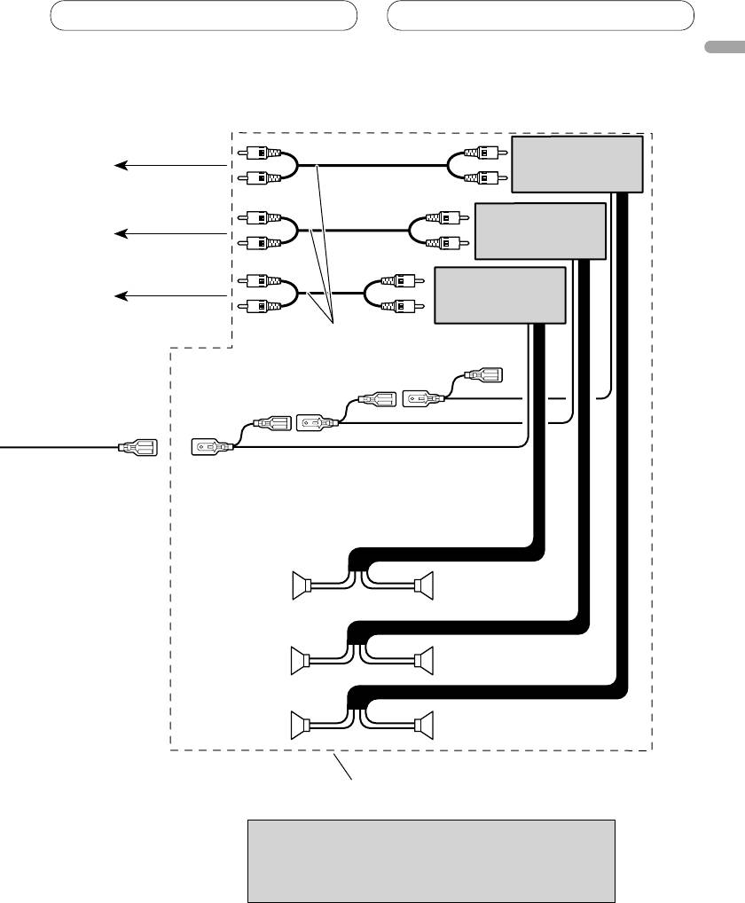
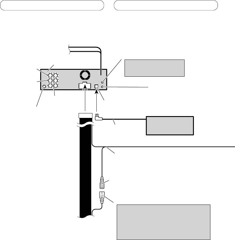
When connecting to separately sold power amp
AUX jack (3.5 φ)
This product
Use a stereo mini plug cable
Rear output
to connect with auxiliary
device.
Front output
Wired remote input
Hard-wired remote control
adaptor can be connected
Subwoofer output
(sold separately).
IP-BUS input (Blue)
Antenna jack
Multi-CD player
(sold separately)
IP-BUS cable
Blue/white
Connect to system control terminal of the
power amp (max. 300 mA 12 V DC).
Blue/white (7*)
Connect to auto-antenna relay control
terminal (max. 300 mA 12 V DC).
Blue/white (6*)
The pin position of the ISO connector will
differ depends on the type of vehicle.
Connect 6* and 7* when Pin 5 is an
antenna control type. In another type of
vehicle, never connect 6* and 7*.
6
Connecting the units
English
Power amp
(sold separately)
To rear output
Power amp
(sold separately)
To front output
Power amp
(sold separately)
To subwoofer output
Connect with RCA cables
(sold separately)
System remote control
RightLeft
Subwoofer
Subwoofer
Front speaker Front speaker
Rear speaker Rear speaker
Perform these connections when using
the optional amplifier.
Note
Change the initial setting of this unit (refer to the
operation manual). The subwoofer output of this unit
is monaural.
7
Installation
Note
DIN Front/Rear-mount
This unit can be properly installed either from
• Check all connections and systems before final
“
Front
”
(conventional DIN Front-mount) or
installation.
“
Rear
”
(DIN Rear-mount installation, utilizing
• Do not use unauthorized parts. The use of
threaded screw holes at the sides of unit
unauthorized parts may cause malfunctions.
chassis). For details, refer to the following
• Consult with your dealer if installation requires
drilling of holes or other modifications of the
installation methods.
vehicle.
• Do not install this unit where:
Removing or attaching
— it may interfere with operation of the vehicle.
— it may cause injury to a passenger as a result
the trim ring
of a sudden stop.
1.
Extend top and bottom of the trim ring
• The semiconductor laser will be damaged if it
overheats. Install this unit away from hot places
outwards to remove the trim ring.
such as near the heater outlet.
•
When reattaching the trim ring, push the trim
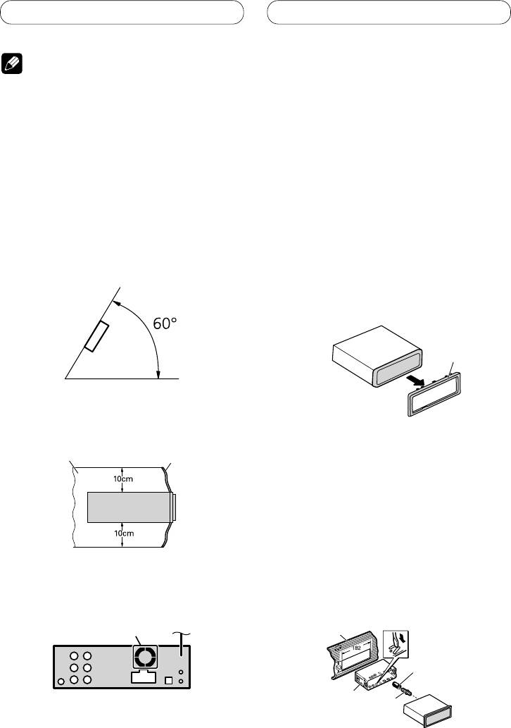
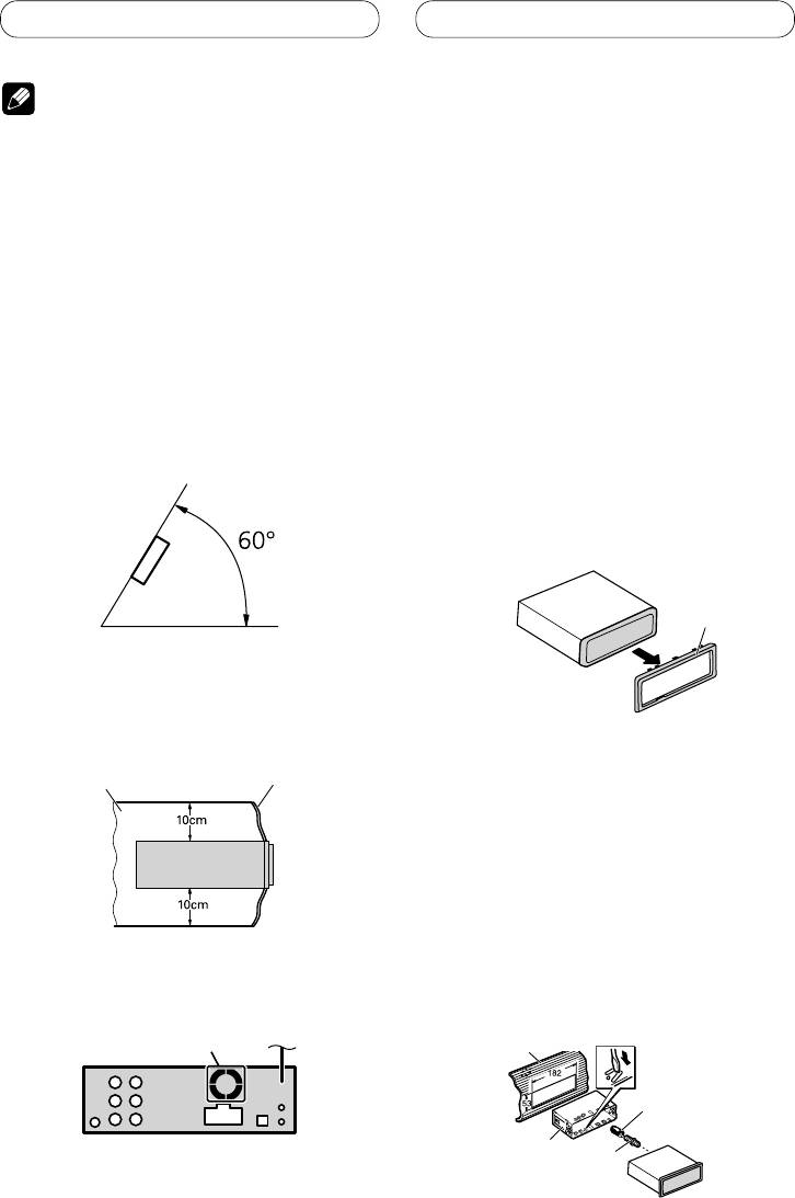
• Optimum performance is obtained when the unit is
ring onto the unit until it clicks. (If the trim ring
installed at an angle of less than 60°.
is attached upside down, the trim ring will not
fit properly.)
•
It becomes easy to remove the trim ring if the
front panel is released.
Trim ring
• When installing, to ensure proper heat dispersal
when using this unit, make sure you leave ample
space behind the rear panel and wrap any loose
cables so they are not blocking the vents.
Leave ample space
Dashboard
DIN Front-mount
Installation with the rubber bush
1. Insert the mounting sleeve into the
dashboard.
• When installing in a shallow space, use a
supplied mounting sleeve. If there is enough
space behind the unit, use factory supplied
mounting sleeve.
• The cords must not cover up the area shown in the
2. Secure the mounting sleeve by using
figure. This is necessary to allow the amplifiers to
a screwdriver to bend the metal tabs
radiate freely.
(90°) into place.
3. Install the unit as illustrated.
Do not cover this area.
Dashboard
Rubber bush
Mounting sleeve
Screw
8

Installation
English
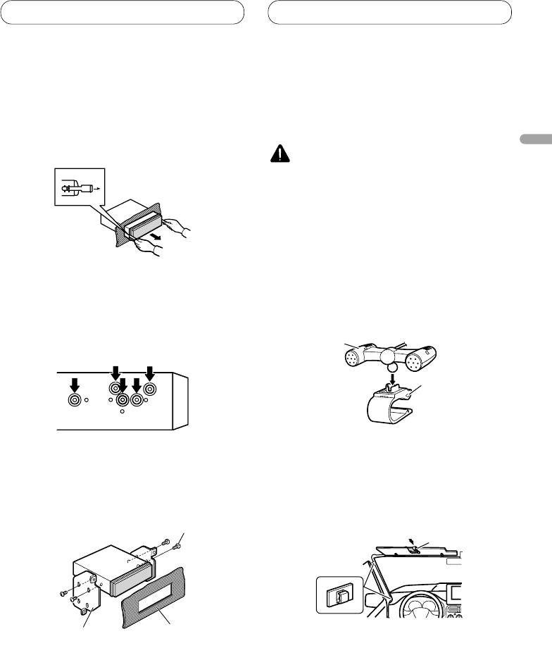
Removing the Unit
Installing the microphone
1. Insert the supplied extraction keys
Install the microphone in a position and
into both sides of the unit until they
orientation that will enable it to pick up the
click into place.
voice of the person operating the system.
2. Pull the unit out of the dashboard.
CAUTION
• It is extremely dangerous to allow the microphone
lead to become wound around the steering
column or gearstick. Be sure to install the unit in
such a way that it will not obstruct driving.
When installing the microphone
on the sun visor
DIN Rear mount
1. Install the microphone on the
1. Determine the appropriate position
microphone clip.
where the holes on the bracket and
the side of the unit match.
Microphone
Microphone clip
2. Install the microphone clip on the sun
visor.
2. Tighten two screws on each side.
• With the sun visor up, install the microphone
• Use either truss screws (5 mm × 8 mm)
clip. (Lowering the sun visor reduces the voice
or flush surface screws (5 mm × 9 mm),
recognition rate.)
depending on the shape of screw holes in the
bracket.
Microphone clip
Screw
Clamp
Dashboard or
Factory radio mounting bracket
• Use separately sold clamps to secure the lead
Console
where necessary inside the vehicle.
9

Installation
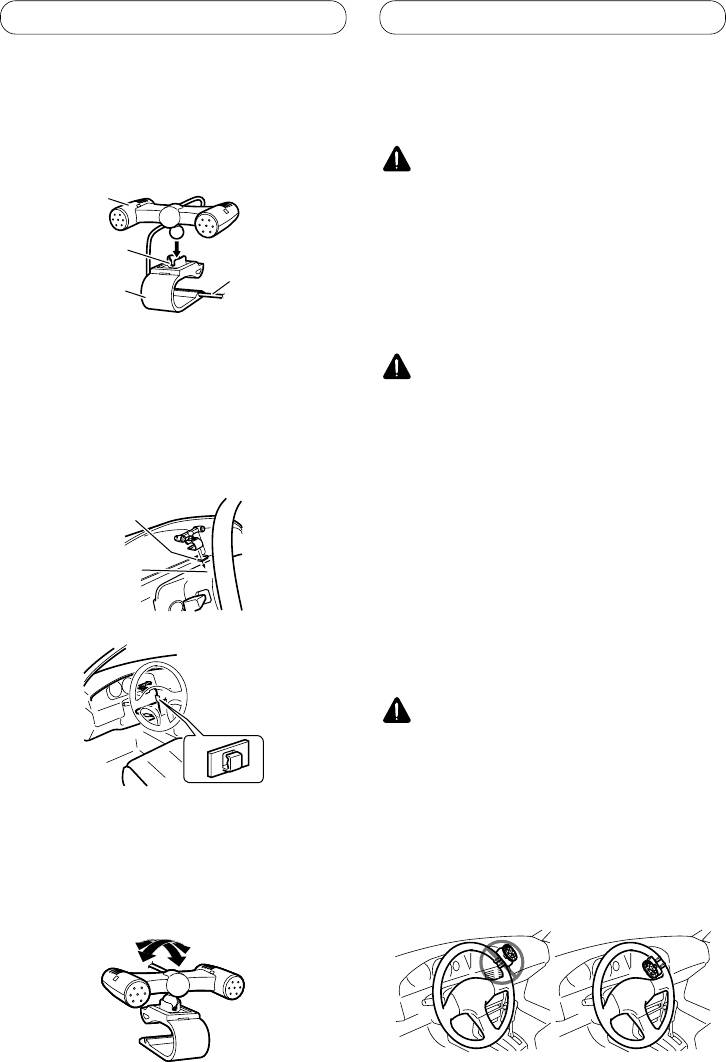
When installing the microphone
Installing the steering remote
on the steering column
control
1. Install the microphone on the
microphone clip.
WARNING
Microphone
• Avoid installing this unit in such a location where
the operation of safety devices such as airbags
is prevented by this unit. Otherwise, there is a
Microphone
Fit the microphone
danger of a fatal accident.
base
lead into the
• Avoid installing this unit in such a location where
groove
the operation of the steering wheel and the
Microphone clip
gearshift lever may be prevented. Otherwise, it
may result in a traffic accident.
• Microphone can be installed without using
CAUTION
microphone clip. In this case, detach the
microphone base from the microphone clip. To
• Installation of this unit requires specialized skills
detach the microphone base from microphone
and experience. Installation of this unit should be
clip, slide the microphone base.
entrusted to a dealer from whom you purchased
this unit.
2. Install the microphone clip on the
• Install this unit using only the parts supplied with
steering column.
this unit. If other parts are used, this unit may be
damaged or could dismount itself, which leads to
an accident or trouble.
Double-sided tape
• Install this unit as required by this manual. Failure
to do so may cause an accident.
• Do not install this unit near the doors where
Install the microphone
rainwater is likely to be spilled on the unit.
clip on the rear side of
Incursion of water into the unit may cause smoke
the steering column.
or fire.
WARNING
• Fix this unit securely to the steering wheel with
the belt attached to the unit. If this unit is loose,
it disturbs driving stability, which may result in a
Clamp
traffic accident.
• Do not attach this unit to the outer circumference
of the steering wheel. Otherwise, it disturbs
driving stability, causing a traffic accident. Always
attach this unit to the inner circumference of the
steering wheel as shown.
• Use separately sold clamps to secure the lead
where necessary inside the vehicle.
Adjusting the microphone angle
The microphone angle can be adjusted.
10
Installation
English
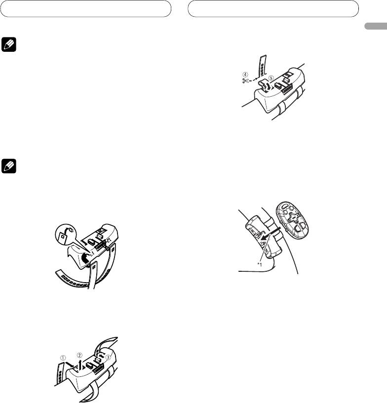
3.
Cut off the extra portion of the belt.
Note
4
• Do not install this unit in such a place as may
obstruct the driver’s view.
• Since interior layout differs depending on the type
of vehicle, the ideal installation location for the
unit also differs. When installing the unit, select
a location that assures optimum transmission of
signals from the unit to the car stereo.
Installing the unit on a left-hand
• 5 If some of the belt still protrudes, fold it back
drive car
into the slot so that it does not interfere with
driving.
Note
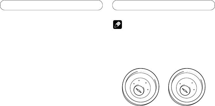
4. Fasten the other belt in the same way.
5. Install the remote control unit in the
• When the unit is installed on a right-hand-drive
holder.
car, the horizontal positions are inverted.
1. Hook the belt on to the holder.
• When removing the remote control unit from
the holder, move the corrugated release section
2. Fix the holder to the inside edge of
toward the steering wheel and slide the remote
the steering wheel so that the holder
control unit toward you.
is facing the driver.
• 12 Wrap the belt around the outside edge of the
steering wheel, passing the end through the slot
in the holder.
3 Pull on the belt to tighten it then secure it using
the other two hooks on the holder.
11
Contenido
Conexión de las unidades
Conexión de las unidades .................... 2
Nota
Conexión del cable de alimentación .............. 4
Cuando conecte a un amplificador de
• Cuando se instale esta unidad en un vehículo
potencia vendido separadamente ............ 6
sin la posición ACC (accesorio) en el interruptor
de encendido, se debe conectar el cable rojo al
Instalación ............................................... 8
terminal que puede detectar la operación de la
Montaje delantero/trasero DIN ....................... 8
llave de encendido.
De lo contrario, la batería puede descargarse.
Extracción o instalación del anillo
compensación ..................................................... 8
Montaje delantero DIN ............................................ 8
A
C
C
O
O
F
N
F
N
Montaje trasero DIN................................................. 9
F
F
O
O
S
S
Instalación del micrófono ................................9
T
T
A
A
R
R
Cuando instale el micrófono en la visera ............... 9
T
T
Cuando instale el micrófono en la base
del volante .......................................................... 10
Ajuste del ángulo del micrófono ........................... 10
Posición ACC
Sin posición ACC
Instalación de la unidad de control remoto
de dirección .............................................. 10
• El uso de esta unidad en condiciones diferentes
Instalación de la unidad en el coche
de las siguientes podría causar un fuego o fallo de
de manejo del lado izquierdo ............................11
funcionamiento.
— Vehículos con una batería de 12 voltios y
puesta a tierra negativa.
— Altavoz con 50 W (valor de salida) y de 4 a 8
ohmios (valor de impedancia).
• Para prevenir cortocircuitos, sobrecalentamiento
o fallo de funcionamiento, asegúrese de seguir las
instrucciones a continuación.
— Desenchufe el terminal negativo de la batería
antes de la instalación.
— Fije el cableado con abrazaderas de cable o
con cinta adhesiva. Para proteger el cableado,
envuélvalo con cinta adhesiva donde el
cableado se apoya sobre piezas metálicas.
— Posicione todos los cables alejados de las
piezas móviles, como el cambio de marchas y
rieles de los asientos.
— Posicione todos los cables alejados de
lugares calientes como cerca de la salida del
calentador.
— No pase el cable amarillo a través de un
agujero en el compartimiento del motor para
conectar la batería.
— Cubra cualquier conector de cable
desconectado con cinta de aislamiento.
— No acorte ningún cable.
— No corte nunca el aislamiento del cable de
alimentación de esta unidad para compartir
la energía con otro equipo. La capacidad de
corriente del cable es limitada.
— Utilice un fusible con la capacidad
especificada.
— No conecte nunca el cable negativo de altavoz
directamente a la puesta a tierra.
— No junte nunca múltiples cables negativos de
altavoz.
2

Conexión de las unidades
• La señal de control se emite a través del cable
azul/blanco cuando se enciende esta unidad.
Conéctelo a un terminal de control de sistema de
amplificador de potencia externo o al terminal de
control de relé de antena automática del vehículo
(máx. 300 mA, 12 V CC). Si el vehículo está
equipado con una antena de vidrio, conéctelo al
terminal de suministro de potencia de refuerzo de
Español
la antena.
• No conecte nunca el cable azul/blanco al
terminal de alimentación de un amplificador
de potencia externo. Igualmente, no conéctelo
nunca al terminal de alimentación de la antena
automática.
De lo contrario, puede ocurrir la descarga de la
batería o un fallo de funcionamiento.
• Los conectores IP-BUS están codificados en
colores. Asegúrese de conectar los conectores del
mismo color.
• El cable negro es para la puesta a tierra. Se debe
conectar este cable y el cable de puesta a tierra
de otro producto (especialmente de productos de
alta corriente como un amplificador de potencia)
separadamente. De lo contrario, puede ocurrir un
fuego o fallo de funcionamiento si los cables se
sueltan accidentalmente.
3
Conexión de las unidades
Conexión del cable de alimentación
Cable USB
Utilice el cable USB suministrado o el cable
USB vendido separadamente (CD-U150E).
Cable de conexión de iPod a USB
Utilice el cable de conexión de iPod a USB
Nota
vendido separadamente (CD-IU50).
Dependiendo del tipo de vehículo, la
función de 3* y 5* puede ser
diferente. En este caso, asegúrese de
conectar 2* a 5* y 4* a 3*.
1*
15 cm
3* 2*
Entrada de micrófono
Micrófono
4 m
4*5*
Conecte los hilos del mismo
color a cada otro.
Tapa (1*)
No quite la tapa
cuando no se utiliza
Fusible (10 A)
este terminal.
Amarillo (3*)
Amarillo (2*)
Reserva
Conecte el terminal de
(o accesorio)
suministro de 12 V constante.
Resistencia de fusible
Rojo (5*)
Rojo (4*)
Accesorio
Conecte al terminal controlado por del
(o reserva)
interruptor de encendido (12 V CC).
Resistencia de fusible
Anaranjado/blanco
Conecte al terminal de interruptor de iluminación.
Negro (masa de la carrocería)
Conecte a un punto de metal limpio, libre de pintura.
Conector ISO
Nota
Nota
Cuando utilice un altavoz de subgraves
En algunos vehículos, puede que el
de 70 W (2 Ω), asegúrese de conectarlo
conector ISO esté dividido en dos. En este
con los hilos Violeta y Violeta/negro de
caso, asegúrese de conectar a ambos
esta unidad. No conecte nada con los
conectores.
hilos Verde y Verde/negro.
4
Conexión de las unidades
1,5 m
Toma de entrada USB1/USB2
20 cm
50 cm
Español
Jack AUX (3,5 φ)
Utilice un cable con clavija
Este producto
Salida trasera
mini estéreo con el equipo
auxiliar.
Salida
delantera
Entrada remota cableada
Se puede conectar el
Salida de altavoz
adaptador de control remoto
de subgraves
cableado (vendido
Entrada IP-BUS (Azul)
Toma de antena
separadamente).
Reproductor de Multi-CD
Cable IP-BUS
(vendido separadamente)
Azul/blanco
Conecte al terminal de control de sistema del
amplificador de potencia (máx. 300 mA 12 V CC).
Azul/blanco (7*)
Conecte al terminal de control de relé de
antena automática (máx. 300 mA 12 V CC).
Azul/blanco (6*)
La posición de los contactos del conector
ISO difiere dependiendo del tipo del
vehículo. Conecte 6* y 7* cuando el
contacto 5 es del tipo de control de antena.
En otros tipos de vehículo, no conecte
nunca 6* y 7*.
Hilos de altavoz
Blanco: Izquierda delantera
Blanco/negro: Izquierda delantera
Gris: Derecha delantera
Gris/negro: Derecha delantera
Verde: Izquierda trasera
o altavoz de subgraves
Verde/negro: Izquierda trasera
o altavoz de subgraves
Violeta: Derecha trasera
o altavoz de subgraves
Violeta/negro: Derecha trasera
o altavoz de subgraves
5
Conexión de las unidades
Cuando conecte a un amplificador de potencia
vendido separadamente
Jack AUX (3,5 φ)
Utilice un cable con clavija
Este producto
mini estéreo con el equipo
Salida trasera
auxiliar.
Salida delantera
Entrada remota cableada
Se puede conectar el
Salida de altavoz
adaptador de control remoto
de subgraves
Entrada IP-BUS (Azul)
cableado (vendido
Toma de antena
separadamente).
Reproductor de Multi-CD
Cable IP-BUS
(vendido separadamente)
Azul/blanco
Conecte al terminal de control de sistema del
amplificador de potencia (máx. 300 mA 12 V CC).
Azul/blanco (7*)
Conecte al terminal de control de relé de
antena automática (máx. 300 mA 12 V CC).
Azul/blanco (6*)
La posición de los contactos del conector
ISO difiere dependiendo del tipo del
vehículo. Conecte 6* y 7* cuando el
contacto 5 es del tipo de control de antena.
En otros tipos de vehículo, no conecte
nunca 6* y 7*.
6

Conexión de las unidades
Amplificador de
potencia (vendido
separadamente)
A la salida trasera
Español
Amplificador de
potencia (vendido
separadamente)
A la salida delantera
Amplificador de
potencia (vendido
A la salida del
separadamente)
altavoz de subgraves
Conecte los cables RCA
(vendidos separadamente)
Control remoto de sistema
DerechaIzquierda
Altavoz de
Altavoz de
subgraves
subgraves
Altavoz delantero Altavoz delantero
Altavoz trasero Altavoz trasero
Realice estas conexiones cuando utilice
el amplificador opcional.
Nota
Cambie el ajuste inicial de esta unidad (refiérase al
manual de operación). La salida de altavoz de subgraves
de esta unidad es monofónica.
7
Instalación
Nota
Montaje delantero/trasero DIN
Se puede instalar esta unidad apropiadamente
• Verifique todas las conexiones y sistemas antes de
mediante el montaje “delantero” (montaje
la instalación final.
delantero DIN convencional) o montaje
• No utilice piezas no autorizadas. El uso de
“trasero” (montaje trasero DIN utilizando
piezas no autorizadas puede causar un fallo de
los agujeros de tornillo roscados en los lados
funcionamiento.
del bastidor de la unidad). Para los detalles,
• Consulte su revendedor si se requiere taladrar
agujeros o hacer otras modificaciones del vehículo
consulte los siguientes métodos de instalación.
para la instalación.
• No instale esta unidad donde:
Extracción o instalación del
— pueda interferir con la operación del vehículo.
— pueda causar lesiones a un pasajero en el caso
anillo compensación
de una parada brusca.
1.
Extienda las partes superior e inferior
• El láser semiconductor se dañará si se
del anillo de compensación hacia fuera
sobrecalienta. Instale esta unidad alejada de
para extraer el anillo de compensación.
lugares calientes como cerca de la salida del
• Cuando reinstale el anillo de compensación,
calentador.
empuje el anillo de compensación en la
• Se obtiene el rendimiento óptimo cuando se instala
unidad hasta que encaje con un “clic”. (Si se
la unidad en un ángulo inferior a 60°.
instala el anillo de compensación invertido,
puede que el anillo de compensación no se
encaje correctamente.)
• Se hace más fácil quitar el anillo de
compensación si se suelta el panel delantero.
Anillo de
compensación
• Cuando instale, para asegurar la dispersión
apropiada del calor durante el uso de esta unidad,
asegúrese de dejar un amplio espacio por detrás
del panel trasero y enrolle cualesquiera cables
sueltos de modo que no bloqueen las aberturas de
ventilación.
Montaje delantero DIN
Deje un amplio espacio
Tablero de instrumentos
Instalación con el buje de caucho
1. Inserte el manguito de montaje en el
tablero de instrumentos.
• Cuando instale en un lugar poco profundo,
utilice el manguito de montaje suministrado.
Si hay espacio suficiente detrás de la unidad,
utilice el manguito de montaje suministrado
de fábrica
• Los cordones no deben tapar el área mostrado en
2. Fije el manguito de montaje utilizando
la figura. Esto es necesario para permitir que los
un destornillador para doblar las
amplificadores puedan radiar libremente.
lengüetas de metal (90°) en posición.
3. Instale la unidad como se muestra.
No cubra esta área.
Tablero de instrumentos
Buje de caucho
Manguito de
Tornillo
montaje
8
Instalación
Extracción de la unidad
Instalación del micrófono
1. Inserte las llaves de extracción
Instale el micrófono en una posición u
suministradas en ambos lados de la
orientación que permita captar bien las voces
unidad hasta que se enganchen en
de la persona que utilice el sistema mediante
posición.
voz.
2. Tire de la unidad del tablero de
Español
instrumentos
PRECAUCIÓN
• Es peligrosísimo dejar que el cable del micrófono
se enrolle en la base del volante o en la palanca
de cambios. Asegúrese de instalar la unidad
de forma que ésta no sea un obstáculo para la
conducción.
Cuando instale el micrófono en
Montaje trasero DIN
la visera
1. Determine la posición apropiada
1. Instale el micrófono en la presilla de
donde los agujeros en la ménsula y el
micrófono.
lado de la unidad se emparejan.
Micrófono
Presilla de micrófono
2. Instale la presilla de micrófono en la
2. Apriete los dos tornillos en cada lado.
visera.
• Utilice tornillos con cabeza ovalada (5 mm ×
• Con la visera hacia arriba, instale la presilla
8 mm) o tornillos de cabeza embutida (5 mm
del micrófono. (Al bajar la visera se reduce la
× 9 mm), dependiendo de la forma de los
capacidad de reconocimiento de mediante
agujeros de tornillo en la ménsula.
voz).
Tornillo
Presilla de micrófono
Abrazadera
Tablero de
Ménsula de montaje
instrumentos o consola
• Utilice abrazaderas vendidas separadamente para
de radio de fábrica
asegurar el cable en el interior del vehículo donde
sea necesario.
9
Instalación
Cuando instale el micrófono en
Instalación de la unidad de
la base del volante
control remoto de dirección
1. Instale el micrófono en la presilla de
micrófono.
ADVERTENCIA
Micrófono
• Evite instalar esta unidad en un lugar en el que
la operación de los dispositivos de seguridad
tales como las bolsas de aire sea impedida por
Fije el cable del
Base del
esta unidad. De otra manera, hay el peligro de un
micrófono en la
micrófono
accidente fatal.
ranura.
• Evite instalar esta unidad en un lugar en el que la
Presilla de
operación del volante y la palanca de cambio sea
micrófono
impedida. De otra manera, podría resultar en un
accidente de tráfico.
• Se puede instalar el micrófono sin utilizar la
presilla de micrófono. En este caso, extraiga la
PRECAUCION
base del micrófono de la presilla de micrófono.
Para extraer la base del micrófono de la presilla
• La instalación de esta unidad requiere de técnicas
de micrófono, deslice la base del micrófono.
especializadas y de experiencia. La instalación
de esta unidad deberá ser encomendada al
2. Instale la presilla de micrófono en la
concesionario a quien comprù esta unidad.
base del volante.
• Instale esta unidad utilizando solamente las
piezas provistas con la misma. Si se utilizara otras
Cinta con adhesivo
piezas, la unidad podría deñarse o desarmarse
de doble cara
por si misma, lo que conllevaría a un accidente o
problema.
• Instale esta unidad tal como se indica en el
Instale la presilla del
manual. Si falla en efectuar la instalación así,
micrófono en el lado
podría causar un accidente.
trasero de la base del
• No instale esta unidad cerca de las puertas donde
volante.
sea probable que el agua de la lluvia se derrame
sobre la unidad. La incursión de agua dentro de
la unidad podría causar la emisión de humos o
incendio.
ADVERTENCIA
Abrazadera
• Fije esta unidad seguramente al volante con
la correa adjunta. Si ésta se aflojara, esto
interrumpirá la estabilidad del manejo, lo que
podría resultar en un accidente de tráfico.
• Utilice abrazaderas vendidas separadamente para
• No instale esta unidad fuera de la circunferencia
asegurar el cable en el interior del vehículo donde
del volante. De otra manera, esto interrumpirá la
sea necesario.
estabilidad del manejo, causando un accidente de
tráfico. Siempre instale esta unidad en el interior
Ajuste del ángulo del micrófono
de la circunferencia del volante, tal como se
indica.
Se puede ajustar el ángulo del micrófono.
10
