Pioneer gm-a6604: Connecting the units
Connecting the units: Pioneer gm-a6604
Black plate (10,1)
Section
03
Connecting the units
WARNING
If the battery wire is not securely fixed to the term-
inal using the terminal screws, there is a risk of
overheating, malfunction and injury, including
minor burns.
1 Route battery wire from engine com-
partment to the vehicle interior.
! When drilling a cable pass-hole into the ve-
hicle body and routing a battery wire thor-
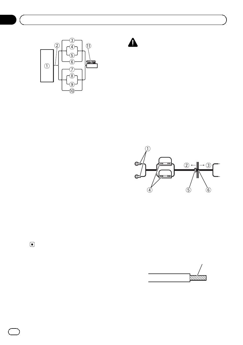
1 Car Stereo
ough it, take care not to short-circuit the
2 Speaker output
wire damaging it by the cut edges or burrs
3 White/black: CH A, Left *
of the hole.
4 White: CH A, Left +
After completing all other amplifier connec-
5 Gray/black: CH A, Right *
tions, finally connect the battery wire terminal
6 Gray: CH A, Right +
of the amplifier to the positive + battery term-
7 Green/black: CH B, Left *
inal.
8 Green: CH B, Left +
9 Violet/black: CH B, Right *
a Violet: CH B, Right +
b Speaker input connector
To speaker input terminal of this unit.
Note
If speaker input wires from a headunit are con-
nected to this amplifier, the amplifier will automa-
tically turn on when the headunit is turned on.
1 Positive + terminal
When the headunit is turned off, the amplifier
2 Engine compartment
turns off automatically. This function may not
3 Vehicle interior
work with some headunits. In such cases, please
4 Fuse (30 A) × 2
use a system remote control wire (sold sepa-
5 Insert the O-ring rubber grommet into the
rately). If multiple amplifiers are to be connected
vehicle body.
together synchronously, connect the head unit
6 Drill a 14 mm hole into the vehicle body.
and all amplifiers via the system remote control
wire.
2 Twist the battery wire, ground wire
and system remote control wire.
Twist
Connecting the power
terminal
The use of a special red battery and ground
wire RD-223 (sold separately) is recom-
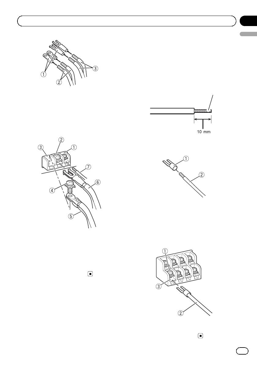
3 Attach lugs to wire ends.
mended. Connect the battery wire directly to
Use pliers, etc., to crimp lugs to wires.
the car battery positive terminal + and the
ground wire to the car body.
10
En
<5707000008290>10
Black plate (11,1)
Section
Connecting the units
03
English
Connecting the speaker
output terminals
1 Use wire cutters or a utility knife to
strip the end of the speaker wires to ex-
pose about 10 mm of wire and then twist
the wire.
Twist
1 Lug (sold separately)
2 Battery wire
3 Ground wire
4 Connect the wires to the terminal.
Fix the wires securely with the terminal
screws.
2 Attach lugs to wire ends.
Use pliers, etc., to crimp lugs to wires.
1 Lug (sold separately)
2 Speaker wire
3 Connect the speaker wires to the
speaker output terminals.
1 System remote control terminal
Fix the speaker wires securely with the term-
2 Ground terminal
inal screws.
3 Power terminal
4 Terminal screws
5 Battery wire
6 Ground wire
7 System remote control wire
1 Terminal screws
2 Speaker wires
3 Speaker output terminals
11
En
<5707000008290>11
Оглавление
- Before you start
- Setting the unit
- Connecting the units
- Connections when using the RCA input jack
- Connecting the units
- Before installing the amplifier
- Additional information
- Avant de commencer
- Réglage de l’appareil
- Connexion des appareils
- Connexions lors de l’utilisation du jack d’entrée RCA
- Connexion des appareils
- Installation
- Informations complémentaires
- Prima di iniziare
- Impostazione dell’unità
- Collegamento delle unità
- Collegamenti utilizzando un connettore di ingresso RCA
- Collegamento delle unità
- Installazione
- Informazioni supplementari
- Antes de comenzar
- Configuración de la unidad
- Conexión de las unidades
- Conexiones al utilizar una toma de entrada RCA
- Conexión de las unidades
- Instalación
- Información adicional
- Bevor Sie beginnen
- Einstellen des Geräts
- Anschließen der Geräte
- Anschlüsse bei Verwendung des Cinch-Eingangs
- Anschließen der Geräte
- Installation
- Zusätzliche Informationen
- Vóór u begint
- Het toestel installeren
- De toestellen aansluiten
- Aansluiting via de RCA-ingang
- De toestellen aansluiten
- Installatie
- Aanvullende informatie
- Перед началом эксплуатации
- Настройка усилителя
- Подключение устройств
- Подключение устройств Перед подключением Режим мостового соединения усилителя
- Подключение устройств
- Подключение с использованием входного гнезда RCA
- Подключение устройств
- Установка
- Дополнительная информация Серийный номер
- Дополнительная информация


