Pioneer gm-a6604: Connecting the units
Connecting the units: Pioneer gm-a6604
Black plate (6,1)
Section
03
Connecting the units
Please see the following section for speaker
Connection diagram
connection instructions. Refer to Connections
when using the speaker input wire on page 9.
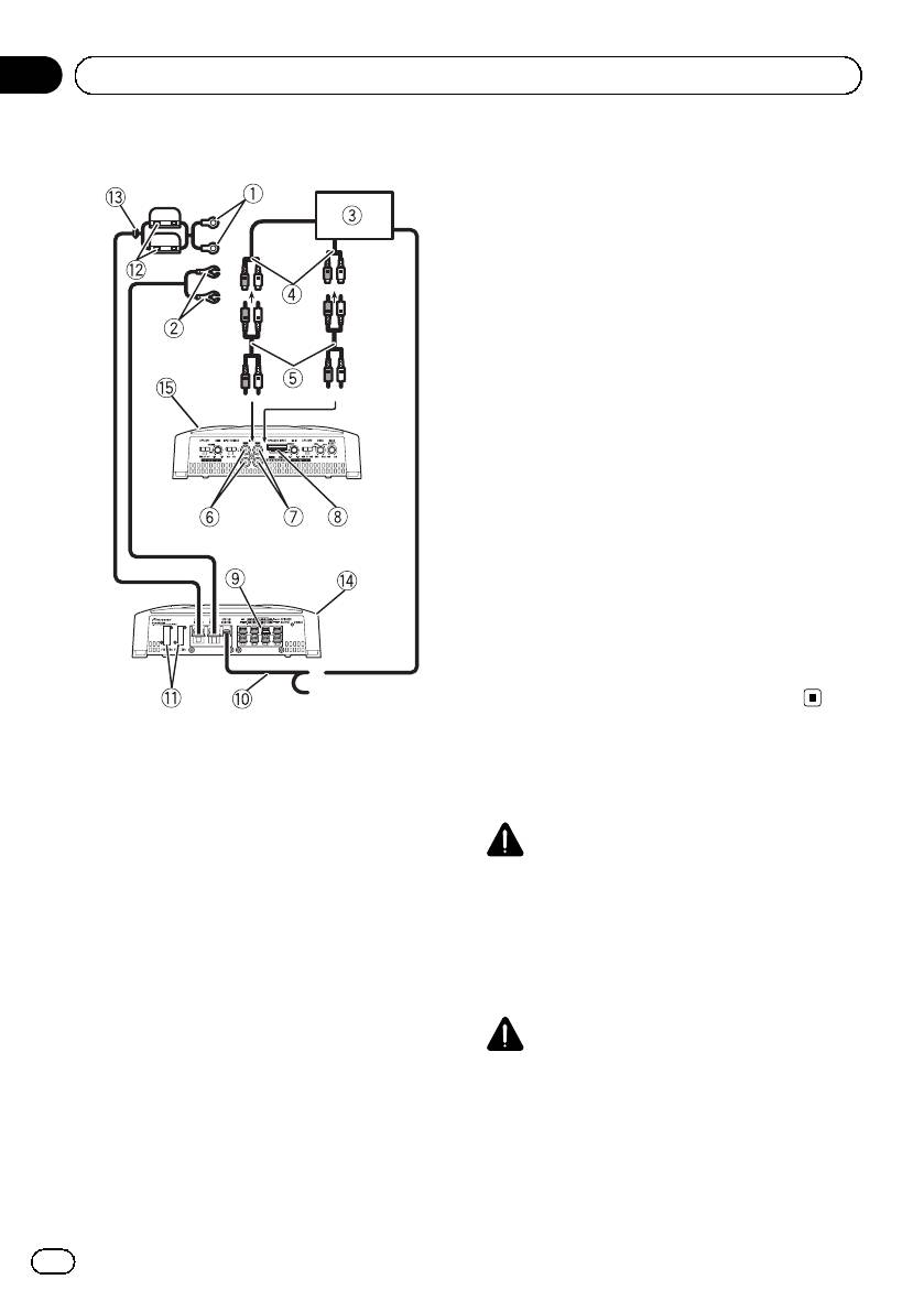
9 Speaker output terminals
Please see the following section for speaker
connection instructions. Refer to Connections
when using the speaker input wire on page 9.
a System remote control wire (sold separately)
Connect male terminal of this wire to the sys-
tem remote control terminal of the car stereo.
The female terminal can be connected to the
auto-antenna relay control terminal. If the car
stereo lacks a system remote control terminal,
connect the male terminal to the power term-
inal via the ignition switch.
b Fuse 25 A × 2 (GM-A6604) / 30 A × 1 (GM-
A4604)
c Fuse (30 A) × 2
d Grommet
e Rear side
f Front side
Note
INPUT SELECT (input select) switch must be set.
For details, see Setting the unit on page 4.
1 Special red battery wire
RD-223 (sold separately)
Before connecting the
After completing all other amplifier connec-
tions, finally connect the battery wire terminal
amplifier
of the amplifier to the positive + battery term-
inal.
WARNING
2 Ground wire (Black)
! Secure the wiring with cable clamps or adhe-
RD-223 (sold separately)
sive tape. To protect the wiring, wrap sections
Connect to metal body or chassis.
in contact with metal parts in adhesive tape.
3 Car stereo with RCA output jacks (sold sepa-
! Never cut the insulation of the power supply
rately)
to feed power to other equipment. Current ca-
4 External output
pacity of the wire is limited.
If only one input plug is used, do not connect
anything to RCA input jack B.
CAUTION
5 Connecting wire with RCA pin plugs (sold se-
! Never shorten any wires, the protection circuit
parately)
may malfunction.
6 RCA input jack A
! Never wire the speaker negative cable directly
7 RCA input jack B
to ground.
8 Speaker input terminal (use a connector in-
! Never band together multiple speaker’s nega-
cluded)
tive cables.
6
En
<5707000008290>6
Black plate (7,1)
Section
Connecting the units
03
English
! If the system remote control wire of the ampli-
About suitable
fier is connected to the power terminal via the
specification of speaker
ignition switch (12V DC), the amplifier will re-
main on with the ignition whether the car
Ensure speakers conform to the following
stereo is on or off, which may exhaust battery
standards, otherwise there is a risk of fire,
if the engine is at rest or idling.
smoke or damage. Speaker impedance is 2 W
! Install and route the separately sold battery
to 8 W,or4W to 8 W for two-channel and other
wire as far as possible from the speaker wires.
bridge connections.
Install and route the separately sold battery
Subwoofer
wire, ground wire, speaker wires and the am-
plifier as far away as possible from the anten-
Speaker channel Power
na, antenna cable and tuner.
Nominal input:
Four-channel output
Min. 60 W (GM-A6604)
Min. 40 W (GM-A4604)
About bridged mode
Nominal input:
Two-channel output
Min. 180 W (GM-A6604)
Min. 120 W (GM-A4604)
Nominal input:
Three-channel
Min. 60 W (GM-A6604)
Speaker output A
Min. 40 W (GM-A4604)
Nominal input:
Three-channel
Min. 180 W (GM-A6604)
Speaker output B
Min. 120 W (GM-A4604)
Other than subwoofer
Speaker channel Power
! Do not install or use this amplifier by wiring
speakers rated at 4 W (or lower) in parallel to
Max. input:
Four-channel output
Min. 120 W (GM-A6604)
achieve a 2 W (or lower) bridged mode (Dia-
Min. 80 W (GM-A4604)
gram B).
Amplifier damage, smoke, and overheating
Max. input:
Two-channel output
Min. 360 W (GM-A6604)
could result from improper bridging. The am-
Min. 240 W (GM-A4604)
plifier surface could also become hot to the
Max. input:
touch and minor burns could result.
Three-channel
Min. 120 W (GM-A6604)
To properly install or use a bridged mode and
Speaker output A
Min. 80 W (GM-A4604)
achieve a 4 W load, wire two 8 W speakers in
Max. input:
parallel with Left + and Right * (Diagram A)
Three-channel
Min. 360 W (GM-A6604)
or use a single 4W speaker.
Speaker output B
Min. 240 W (GM-A4604)
In addition, refer to the speaker instruction
manual for information on the correct connec-
tion procedure.
! For any further enquiries, contact your local
authorized Pioneer dealer or customer
service.
7
En
<5707000008290>7
Black plate (8,1)
Section
03
Connecting the units
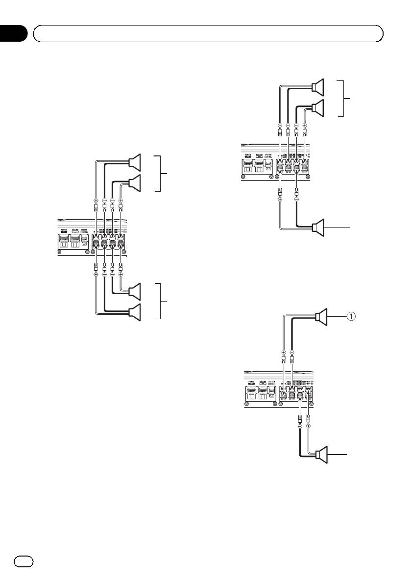
Three-channel output
Connecting the speakers
The speaker output mode can be four-channel,
1
three-channel (stereo and mono) or two-chan-
3
nel (stereo or mono). Connect the speaker
2
leads based on the mode and the figures
shown below.
Four-channel output
1
3
2
4
1 Right
2 Left
3 Speaker out A
4 Speaker out B (Mono)
2
Two-channel output (Stereo)
4
1
1 Right
2 Left
3 Speaker out A
4 Speaker out B
2
1 Speaker (Right)
2 Speaker (Left)
8
En
<5707000008290>8
Оглавление
- Before you start
- Setting the unit
- Connecting the units
- Connections when using the RCA input jack
- Connecting the units
- Before installing the amplifier
- Additional information
- Avant de commencer
- Réglage de l’appareil
- Connexion des appareils
- Connexions lors de l’utilisation du jack d’entrée RCA
- Connexion des appareils
- Installation
- Informations complémentaires
- Prima di iniziare
- Impostazione dell’unità
- Collegamento delle unità
- Collegamenti utilizzando un connettore di ingresso RCA
- Collegamento delle unità
- Installazione
- Informazioni supplementari
- Antes de comenzar
- Configuración de la unidad
- Conexión de las unidades
- Conexiones al utilizar una toma de entrada RCA
- Conexión de las unidades
- Instalación
- Información adicional
- Bevor Sie beginnen
- Einstellen des Geräts
- Anschließen der Geräte
- Anschlüsse bei Verwendung des Cinch-Eingangs
- Anschließen der Geräte
- Installation
- Zusätzliche Informationen
- Vóór u begint
- Het toestel installeren
- De toestellen aansluiten
- Aansluiting via de RCA-ingang
- De toestellen aansluiten
- Installatie
- Aanvullende informatie
- Перед началом эксплуатации
- Настройка усилителя
- Подключение устройств
- Подключение устройств Перед подключением Режим мостового соединения усилителя
- Подключение устройств
- Подключение с использованием входного гнезда RCA
- Подключение устройств
- Установка
- Дополнительная информация Серийный номер
- Дополнительная информация


