Pioneer VSX-920-K: Connecting your equipment
Connecting your equipment: Pioneer VSX-920-K
Connecting your equipment 03
Chapter 3:
English
Connecting your equipment
This receiver provides you with many connection possibilities, but it doesn’t have to be difficult.
This page explains the kinds of components you can connect to make up your home theater system.
Deutsch
Important
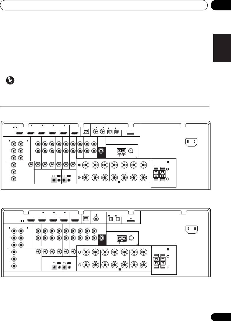
• Illustration shows the VSX-1020, however connections for the VSX-1025 and the VSX-920 are
the same except where noted.
Français
Rear panel
Italiano
Nederlands
Español
15
En
HDMI
BD IN IN IN IN IN
1
2 3 4
OUT
LAN
COAXIAL
ASSIGNABLE
OPTICAL
ASSIGNABLE
1 4
(
10/100
)
IN
1
IN
2
ASSIGNABLE
IN
1
IN
2
ADAPTER PORT
(
OUTPUT 5 V 100 mA MAX
)
AC IN
(
DVD
)
(
CD
)
(
TV/SAT
)
(
DVR/BDR
)
COMPONENT VIDEO
AUDIO
IN
1
ASSIGNABLE
IN
2
PRE OUT
(
DVD
)
(
DVR/BDR
)
Y
Y
L
ANTENNA
PB
P
B
R
ZONE 2
DVR/BDR
DVD
TV/SAT
VIDEO
CD
CD-R/TAPE
SUBWOOFER
PR
PR
OUT
OUT IN
IN
IN
IN
OUT ININ
AM LOOP
FM UNBAL 75
FRONT CENTER SURROUND
SURROUND BACK
R
LR LR L
(
Single
)
SPEAKERS
MONITOR
FRONT HEIGHT/WIDE/
B
Y
OUT
RL
VIDEO
P
B
IR CONTROL
IN
OUT
IN
OUT
PR
SPEAKERS
A
VSX-1020/VSX-1025
BD IN IN IN IN
1
2 3
OUT
LAN
COAXIAL
ASSIGNABLE
OPTICAL
(
10/100
)
IN
1
ASSIGNABLE
IN
1
IN
2
HDMI
ADAPTER PORT
ASSIGNABLE
(
OUTPUT 5 V 100 mA MAX
)
1 3
AC IN
(
DVD
)
(
TV/SAT
)
(
DVR/BDR
)
COMPONENT VIDEO
AUDIO
IN
1
ASSIGNABLE
IN
2
PRE OUT
(
DVD
)
(
DVR/BDR
)
Y
Y
L
ANTENNA
PB
P
B
R
ZONE 2
DVR/BDR
DVD
TV/SAT
VIDEO 1
CD
CD-R/TAPE
SUBWOOFER
PR
PR
OUT
OUT IN
IN
IN
IN
OUT ININ
AM LOOP
FM UNBAL 75
FRONT CENTER SURROUND
SURROUND BACK
R
LR LR L
Single
(
)
SPEAKERS
MONITOR
FRONT HEIGHT/WIDE/
B
Y
OUT
RL
VIDEO
P
B
IR CONTROL
IN
OUT
IN
OUT
PR
SPEAKERS
A
VSX-920
VSX-1020_SYXCN.book 15 ページ 2010年3月12日 金曜日 午前9時10分
VSX-1020_SYXCN.book 16 ページ 2010年3月12日 金曜日 午前9時10分
Connecting your equipment03
CAUTION
• Before making or changing the
connections, switch off the power and
disconnect the power cord from the power
outlet. Plugging in should be the final step.
Important
• The input functions below are assigned by
default to the receiver’s different input
terminals. Refer to The Input Setup menu
on page 42 to change the assignments if
other connections are used.
Input Terminals
Input
function
Digital HDMI
Component
DVD COAX-1 IN 1
BD (BD)
TV/SAT OPT-1
DVR/BDR OPT-2 IN 2
HDMI 1
(HDMI-1)
HDMI 2
(HDMI-2)
HDMI 3
(HDMI-3)
a
HDMI 4
(HDMI-4)
a
HDMI 5
(HDMI-5)
(front panel)
a
CD COAX-2
a. VSX-1020/VSX-1025 only
16
En
Connecting your equipment 03
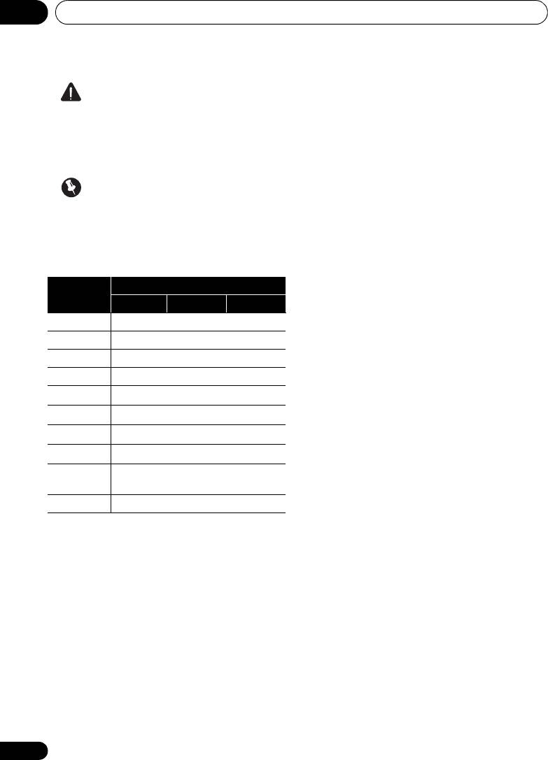
[B] 9.1 channel surround system (Front
English
Determining the speakers’
wide)
•
Speaker System setting: Normal(SB/FW)
application
This unit permits you to build various surround
systems, in accordance with the number of
speakers you have.
R
Deutsch
FWR
• Be sure to connect speakers to the front
L
left and right channels (L and R).
C
SR
• It is also possible to only connect one of the
SW
surround back speakers (SB) or neither.
FWL
Choose one from Plans [A] to [E] below.
Français
SBR
SL
[A] 9.1 channel surround system (Front
SBL
height)
*Default setting
This plan replaces the left and right front
• Speaker System setting: Normal(SB/FH)
height speakers shown in [A] with the left and
Italiano
right front wide speakers (FWL/FWR).
FHR
This surround system produces a true-to-life
FHL
R
sound over a wider area.
[C] 7.1 channel surround system &
L
Nederlands
C
SR
Speaker B connection
SW
• Speaker System setting: Speaker B
SBR
SL
SBL
Español
R
A 9.1 ch surround system connects the left and
L
right front speakers (L/R), the center speaker
R
C
SR
L
(C), the left and right front height speakers
SW
(FHL/FHR), the left and right surround
speakers (SL/SR), the left and right surround
back speakers (SBL/SBR), and the subwoofer
SBR
SL
(SW).
SBL
This surround system produces a more true-to-
life sound from above.
With these connections you can
simultaneously enjoy 5.1-channel surround
sound in the main zone with stereo playback of
the same sound on the B speakers. The same
connections also allow for 7.1-channel
surround sound in the main zone when not
using the B speakers.
17
En
Speaker B
VSX-1020_SYXCN.book 17 ページ 2010年3月12日 金曜日 午前9時10分
Connecting your equipment03
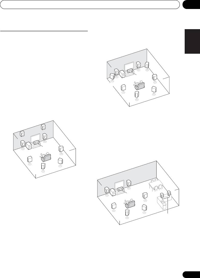
[D] 5.1 channel surround system & Front
Important
Bi-amping connection (High quality
•The Speaker System setting must be
surround)
made if you use any of the connections
• Speaker System setting: Front Bi-Amp
shown above other than [A] (see Speaker
Bi-amping connection of the front speakers for
system setting on page 101).
high sound quality with 5.1-channel surround
• Sound does not come through
sound.
simultaneously from the front height, front
wide, speaker B and surround back
speakers. Output speakers are different
depending on the input signal or listening
mode.
Other speaker connections
• Your favorite speaker connections can be
selected even if you have fewer than 5.1
speakers (except front left/right speakers).
• When not connecting a subwoofer,
connect speakers with low frequency
reproduction capabilities to the front
[E] 5.1 channel surround system & ZONE
channel. (The subwoofer’s low frequency
2 connection (Multi Zone)
component is played from the front
• Speaker System setting: ZONE 2
speakers, so the speakers could be
damaged.)
With these connections you can
simultaneously enjoy 5.1-channel surround
• After connecting, be sure to conduct
sound in the main zone with stereo playback
the Auto MCACC (speaker environment
on another component in ZONE 2 (The
setting) procedure.
selection of input devices is limited.)
See Automatically conducting optimum
sound tuning (Auto MCACC) on page 39.
18
En
R
L
C
SW
SR
SL
Front Bi-Amp
R
L
C
SW
SR
SL
R
L
Main zone
Sub zone
ZONE 2
VSX-1020_SYXCN.book 18 ページ 2010年3月12日 金曜日 午前9時10分
Connecting your equipment 03
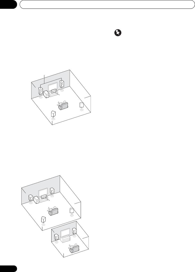
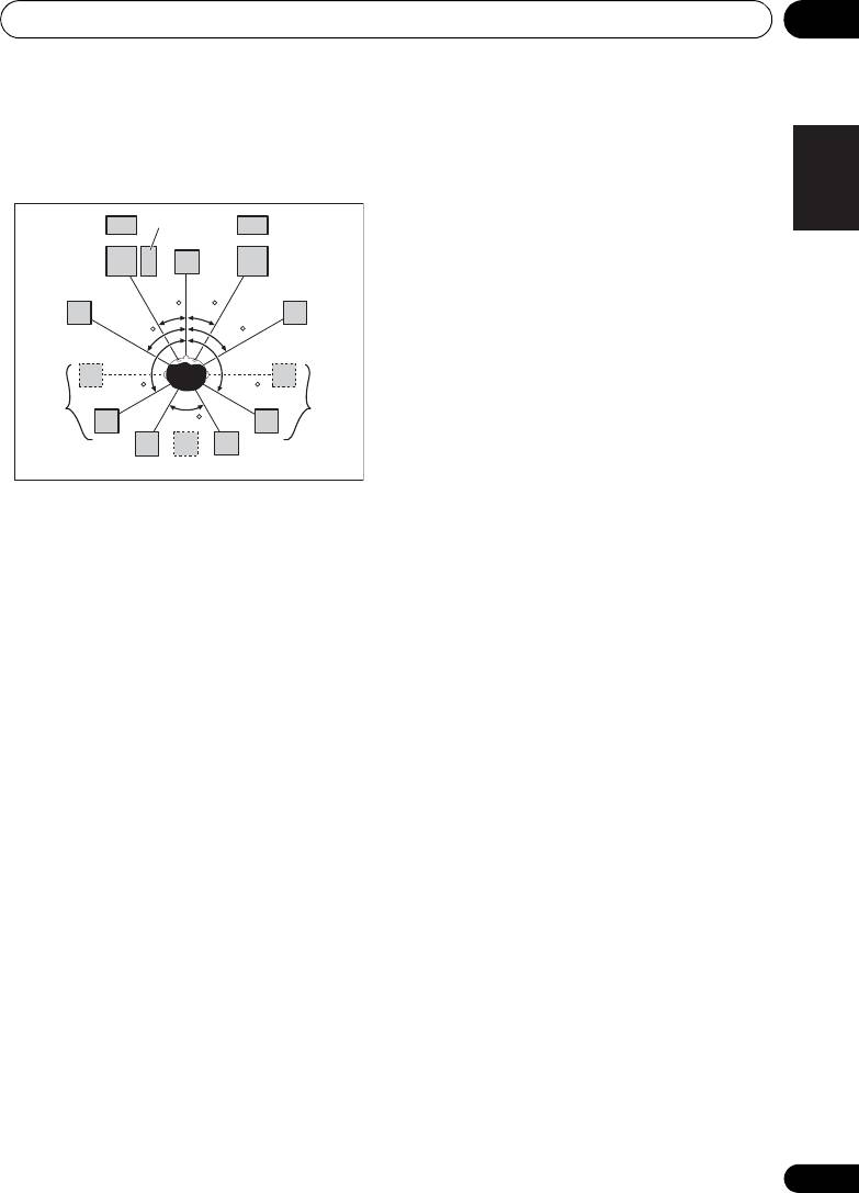
Placing the speakers
Some tips for improving sound quality
English
Refer to the chart below for placement of the
Where you put your speakers in the room has
speakers you intend to connect.
a big effect on the quality of the sound. The
following guidelines should help you to get the
best sound from your system.
• The subwoofer can be placed on the floor.
Deutsch
Ideally, the other speakers should be at
about ear-level when you’re listening to
them. Putting the speakers on the floor
(except the subwoofer), or mounting them
very high on a wall is not recommended.
Français
• For the best stereo effect, place the front
speakers 2 m to 3 m apart, at equal
distance from the TV.
• If you’re going to place speakers around
your CRT TV, use shielded speakers or
• Place the surround speakers at 120º from
place the speakers at a sufficient distance
Italiano
the center. If you, (1) use the surround back
from your CRT TV.
speaker, and, (2) don’t use the front height
• If you’re using a center speaker, place the
speakers / front wide speakers, we
front speakers at a wider angle. If not,
recommend placing the surround speaker
place them at a narrower angle.
right beside you.
Nederlands
• Place the center speaker above or below
• If you intend to connect only one surround
the TV so that the sound of the center
back speaker, place it directly behind you.
channel is localized at the TV screen. Also,
• Place the left and right front height
make sure the center speaker does not
speakers at least 1 m directly above the left
cross the line formed by the leading edge
and right front speakers.
of the front left and right speakers.
Español
• It is best to angle the speakers towards the
listening position. The angle depends on
the size of the room. Use less of an angle
for bigger rooms.
• Surround and surround back speakers
should be positioned 60 cm to 90 cm higher
than your ears and tilted slightly downward.
Make sure the speakers don’t face each
other. For DVD-Audio, the speakers should
be more directly behind the listener than for
home theater playback.
• Try not to place the surround speakers
farther away from the listening position
than the front and center speakers. Doing
so can weaken the surround sound effect.
19
En
SW
FHL
FHR
C
L
R
30 30
FWL
FWR
60
60
120 120
SL
SR
60
SBL
SB
SBR
VSX-1020_SYXCN.book 19 ページ 2010年3月12日 金曜日 午前9時10分
Connecting your equipment03
Important
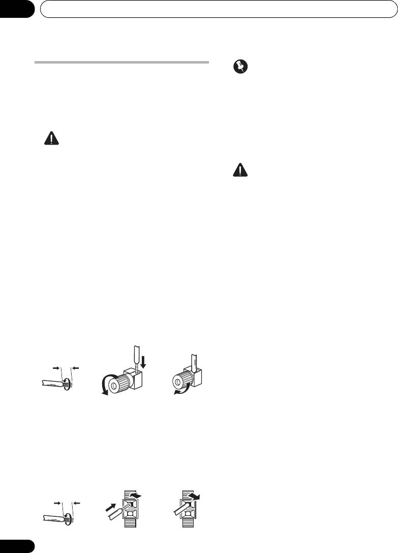
Connecting the speakers
Each speaker connection on the receiver
• Please refer to the manual that came with
comprises a positive (+) and negative (–)
your speakers for details on how to connect
terminal. Make sure to match these up with the
the other end of the speaker cables to your
terminals on the speakers themselves.
speakers.
• Use an RCA cable to connect the subwoofer.
It is not possible to connect using speaker
CAUTION
cables.
• These speaker terminals carry
HAZARDOUS LIVE voltage. To prevent
CAUTION
the risk of electric shock when connecting
or disconnecting the speaker cables,
• Make sure that all speakers are securely
disconnect the power cord before touching
installed. This not only improves sound
any uninsulated parts.
quality, but also reduces the risk of
• Make sure that all the bare speaker wire is
damage or injury resulting from speakers
twisted together and inserted fully into the
being knocked over or falling in the event of
speaker terminal. If any of the bare speaker
external shocks such as earthquakes.
wire touches the back panel it may cause
the power to cut off as a safety measure.
Bare wire connections
A-Speaker terminals:
1 Twist exposed wire strands together.
2 Loosen terminal and insert exposed wire.
3 Tighten terminal.
B-Speaker terminals:
1 Twist exposed wire strands together.
2 Push open the tabs and insert exposed
wire.
3 Release the tabs.
20
En
12 3
10 mm
12 3
10 mm
VSX-1020_SYXCN.book 20 ページ 2010年3月12日 金曜日 午前9時10分
Connecting your equipment 03
English
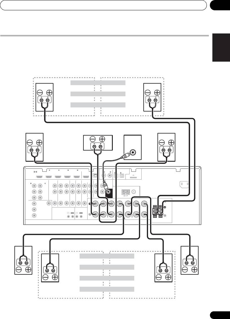
Installing your speaker system
At the very least, front left and right speakers only are necessary. Note that your main surround
speakers should always be connected as a pair, but you can connect just one surround back
speaker if you like (it must be connected to the left surround back terminal).
Deutsch
Français
Italiano
Nederlands
Español
21
En
LINE LEVEL
INPUT
HDMI
BD IN IN IN IN IN
1
2 3 4
OUT
LAN
COAXIAL
ASSIGNABLE
OPTICAL
ASSIGNABLE
1 4
(
10/100
)
IN
1
IN
2
ASSIGNABLE
IN
1
IN
2
ADAPTER PORT
(
OUTPUT 5 V 100 mA MAX
)
AC IN
(
DVD
)
(
CD
)
(
TV/SAT
)
(
DVR/BDR
)
COMPONENT VIDEO
ASSIGNABLE
AUDIO
PRE OUT
IN
1
IN
2
(
DVD
)
(
DVR/BDR
)
L
Y
Y
ANTENNA
P
B
P
B
R
ZONE 2
DVR/BDR
DVD
TV/SAT
VIDEO
CD
CD-R/TAPE
SUBWOOFER
P
R
P
R
OUT
OUT IN
IN
IN
IN
OUT ININ
AM LOOP
FM UNBAL 75
FRONT CENTER SURROUND
SURROUND BACK
R
LR LR L
Single
(
)
SPEAKERS
MONITOR
FRONT HEIGHT/WIDE/
B
Y
OUT
RL
VIDEO
P
B
IR CONTROL
IN
OUT
IN
OUT
P
R
SPEAKERS
A
The front height terminals can also be used for
the front wide and Speaker B speakers.
Front height setting
Front height right
Front height left
Front wide setting
Front wide right
Front wide left
Speaker B setting
Speaker B - right
Speaker B - left
Front right
Front left
Center
Subwoofer
VSX-1020/VSX-1025
The surround back terminals
can also be used for ZONE2.
5.1 ch surround setting
Not connected
Not connected
6.1 ch surround setting
Not connected
Surround back
Surround right
7.1 ch surround setting
Surround left
Surround back right
Surround back left
ZONE 2 setting
ZONE 2 - right
ZONE 2 - left
VSX-1020_SYXCN.book 21 ページ 2010年3月12日 金曜日 午前9時10分
Connecting your equipment03
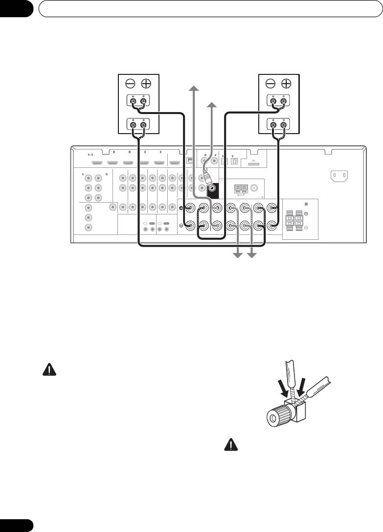
Bi-amping your speakers
Bi-amping is when you connect the high
Bi-wiring your speakers
frequency driver and low frequency driver of
Your speakers can also be bi-wired if they
your speakers to different amplifiers for better
support bi-amping.
crossover performance. Your speakers must be
• With these connections, the Speaker
bi-ampable to do this (having separate
System setting makes no difference.
terminals for high and low) and the sound
improvement will depend on the kind of
• To bi-wire a speaker, connect two speaker
speakers you’re using.
cords to the speaker terminal on the receiver.
CAUTION
• Most speakers with both High and Low
terminals have two metal plates that
connect the High to the Low terminals.
These must be removed when you are bi-
amping the speakers or you could severely
damage the amplifier. See your speaker
manual for more information.
CAUTION
• If your speakers have a removable
• Don’t connect different speakers from the
crossover network, make sure you do not
same terminal in this way.
remove it for bi-amping. Doing so may
• When bi-wiring as well, heed the cautions
damage your speakers.
for bi-amping shown at the left.
22
En
High
High
Low
Low
HDMI
BD IN IN IN IN IN
1
2 3 4
OUT
LAN
COAXIAL
ASSIGNABLE
OPTICAL
ASSIGNABLE
1 4
(
10/100
)
IN
1
IN
2
ASSIGNABLE
IN
1
IN
2
ADAPTER PORT
IN
(
OUTPUT 5 V 100 mA MAX
)
(
)
(
)
(
)
(
)
AC IN
DVD
CD
TV/SAT
DVR/BDR
COMPONENT VIDEO
ASSIGNABLE
AUDIO
PRE OUT
IN
1
IN
2
(
DVD
)
(
DVR/BDR
)
L
Y
Y
ANTENNA
PB
P
B
R
ZONE 2
DVR/BDR
DVD
TV/SAT
VIDEO
CD
CD-R/TAPE
SUBWOOFER
PR
PR
OUT
OUT IN
IN
IN
IN
OUT ININ
AM LOOP
FM UNBAL 75
FRONT CENTER SURROUND
SURROUND BACK
R
LR LR L
(
Single
)
SPEAKERS
MONITOR
FRONT HEIGHT/WIDE/
B
Y
OUT
RL
VIDEO
P
B
IR CONTROL
IN
OUT
IN
OUT
PR
SPEAKERS
A
Front right
Center
Front left
Subwoofer
Bi-amp compatible
Bi-amp compatible
speaker
speaker
VSX-1020/VSX-1025
Surround right
Surround left
VSX-1020_SYXCN.book 22 ページ 2010年3月12日 金曜日 午前9時10分

VSX-1020_SYXCN.book 23 ページ 2010年3月12日 金曜日 午前9時10分
Connecting your equipment 03
Bi-Amping setup
English
Selecting the Speaker system
Bi-amping connection of the front speakers for
The front height terminals can be used for front
high sound quality with 5.1-channel surround
wide and Speaker B connections, in addition to
sound.
for the front height speakers. Also, the
1 Connect a Bi-amp compatible speakers to
surround back terminals can be used for bi-
the front and surround back speaker
Deutsch
amping and ZONE 2 connections, in addition
terminals.
to for the surround back speakers. Make this
See Bi-amping your speakers on page 22.
setting according to the application.
2 Select ‘
Front Bi-Amp
’ from the
Speaker
Front height setup
System
menu.
*Default setting
See Speaker system setting on page 101 to do
Français
1 Connect a pair of speakers to the front
this.
height speaker terminals.
ZONE 2 setup
See Connecting the speakers on page 20.
With these connections you can
2 If necessary, select ‘
Normal(SB/FH)
’ from
simultaneously enjoy 5.1-channel surround
the
Speaker System
menu.
sound in the main zone with stereo playback
Italiano
See Speaker system setting on page 101 to do
on another component in ZONE 2.
this.
1 Connect a pair of speakers to the
Front wide setup
surround back speaker terminals.
See Connecting the speakers on page 20.
1 Connect a pair of speakers to the front
Nederlands
height speaker terminals.
2 Select ‘
ZONE 2
’ from the
Speaker
See Connecting the speakers on page 20.
System
menu.
See Speaker system setting on page 101 to do
2 Select ‘
Normal(SB/FW)
’ from the
this.
Speaker System
menu.
See Speaker system setting on page 101 to do
Español
this.
Speaker B setup
You can listen to stereo playback in another
room.
1 Connect a pair of speakers to the front
height speaker terminals.
See Connecting the speakers on page 20.
2 Select ‘
Speaker B
’ from the
Speaker
System
menu.
See Speaker system setting on page 101 to do
this.
23
En
Connecting your equipment03
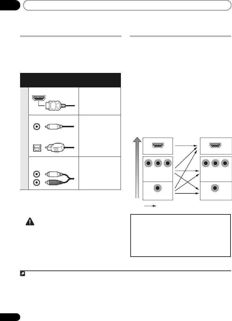
About the
audio connection
About the video converter
There are several types of audio input and output
The video converter ensures that all video
terminals on this receiver. The receiver selects
sources are output through all of the
the first available signal in the following order
MONITOR OUT jacks. The only exception is
when you choose
AUTO
as the input signal:
HDMI: since this resolution cannot be
downsampled, you must connect your
Types of cables and
Transferable
monitor/TV to the receiver’s HDMI video
terminals
audio signals
1
outputs when connecting this video source.
HDMI HD audio
If several video components are assigned to
the same input function (see The Input Setup
menu on page 42), the converter gives priority
to HDMI, component, then composite (in that
order).
Digital (Coaxial) Conventional
digital audio
Sound signal priority
Digital (Optical)
RCA (Analog)
Conventional
(White/Red)
analog audio
• With an HDMI cable, video and audio
signals can be transferred in high quality
over a single cable.
CAUTION
• When connecting optical cables, be careful
when inserting the plug not to damage the
shutter protecting the optical socket.
• When storing optical cable, coil loosely.
The cable may be damaged if bent around
sharp corners.
24
En
Note
HDMI IN
HDMI OUT
Y
P
B
P
R
Y
P
B
P
R
COMPONENT
COMPONENT VIDEO
VIDEO IN
MONITOR OUT
VIDEO IN
VIDEO
MONITOR OUT
1 • If the video signal does not appear on your TV, try adjusting the resolution settings on your component or display.
Note that some components (such as video game units) have resolutions that may not be converted. In this case, try
switching Digital Video Conversion (in Setting the Video options on page 71) OFF.
• The signal input resolutions that can be converted from the component video input for the HDMI output are 480i/
576i, 480p/576p, 720p and 1080i. 1080p signal cannot be converted.
• Only signals with an input resolution of 480i/576i can be converted from the component video input for the
composite MONITOR OUT terminals.
Terminal for
Terminal for
connection with
connection with TV
source device
monitor
High picture quality
Video signals can be output
This product incorporates copyright protection
technology that is protected by U.S. patents and other
intellectual property rights. Use of this copyright
protection technology must be authorized by Rovi
Corporation, and is intended for home and other limited
viewing uses only unless otherwise authorized by Rovi
Corporation. Reverse engineering or disassembly is
prohibited.
VSX-1020_SYXCN.book 24 ページ 2010年3月12日 金曜日 午前9時10分
Connecting your equipment 03
English
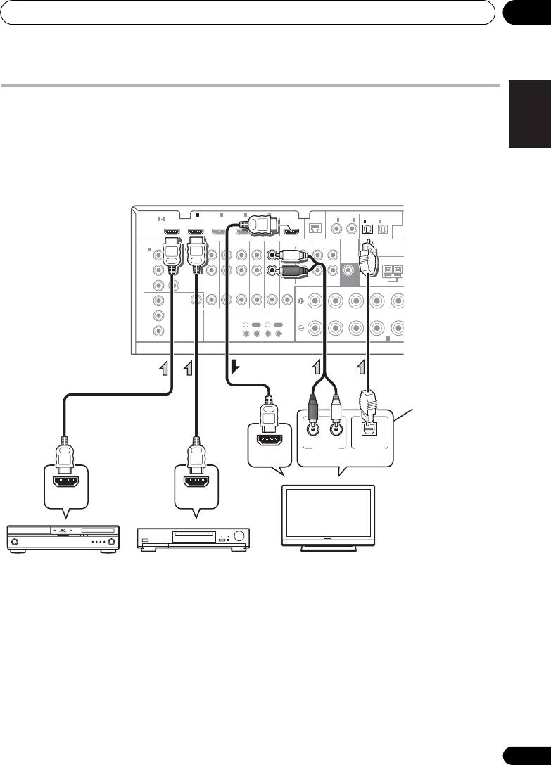
Connecting your TV and playback components
Connecting using HDMI
If you have an HDMI or DVI (with HDCP) equipped component (BD: Blu-ray disc player, etc.), you
can connect it to this receiver using a commercially available HDMI cable.
Deutsch
If the TV and playback components support the Control with HDMI function, the convenient
Control with HDMI functions can be used (see Control with HDMI function on page 63).
HDMI
ASSIGNABLE
ASSIGNABLE
ASSIGNABLE
(
OUTPU
(
DVD
)
(
DVR/BDR
)
ASSIGNABLE
Français
(
DVD
)
(
DVR/BDR
)
L
Y
Y
P
B
P
B
R
ZONE 2
DVR/BDR
DVD
TV/SAT
VIDEO
CD
CD-R/TAPE
P
R
P
R
OUT
OUT IN
IN
IN
IN
OUT ININ
FRONT CENTER SURROUND
R
LR
Y
P
B
Italiano
P
R
Nederlands
Español
• For input components, connections other
than HDMI connections are also possible
(see Connecting your DVD player with no
HDMI output on page 27).
• If you want to listen to the sound of the TV
over the receiver, connect the receiver and
TV with audio cables.
25
En
T
OPTICAL
(
CD
)
(
TV/SAT
)
COMPONENT VIDEO
AUDIO
PRE OUT
ANTENNA
SUBWOOFER
AM LOOP
A
BD IN IN IN IN IN
1
2 3 4
OUT
LAN
COAXIAL
1 4
10/100
(
)
IN
1
IN
2
IN
1
IN
2
IN
1
IN
2
MONITOR
OUT
VIDEO
IR CONTROL
IN
OUT
IN
OUT
SPEAKERS
A
RL
ANALOG
OPTICAL
AUDIO OUT
DIGITAL OUT
HDMI IN
HDMI OUT HDMI OUT
VSX-1020/
VSX-1025
This connection is
required in order to
listen to the sound of
the TV over the receiver.
Select one
HDMI/DVI-compatible
Other HDMI/DVI-
HDMI/DVI-compatible TV
Blu-ray disc player
equipped component
VSX-1020_SYXCN.book 25 ページ 2010年3月12日 金曜日 午前9時10分

Connecting your equipment03
1
• Input of the following digital audio
About HDMI
4
formats:
The HDMI connection transfers
– Dolby Digital, Dolby Digital Plus, DTS,
uncompressed digital video, as well as almost
High bitrate audio (Dolby TrueHD, DTS-HD
every kind of digital audio that the connected
Master Audio, DTS-HD High Resolution
component is compatible with, including DVD-
Audio), DVD-Audio, CD, SACD (DSD
Video, DVD-Audio, SACD, Dolby Digital Plus,
signal), Video CD, Super VCD
Dolby TrueHD, DTS-HD Master Audio (see
• Synchronized operation with components
below for limitations), Video CD/Super VCD
using the Control with HDMI function (see
and CD. See About the video converter on
Control with HDMI function on page 63).
page 24 for more on HDMI compatibility.
HDMI, the HDMI Logo and High-Definition
This receiver incorporates High-Definition
®
Multimedia Interface are trademarks or
Multimedia Interface (HDMI
) technology.
registered trademarks of HDMI Licensing, LLC in
This receiver supports the functions described
the United States and other countries.
2
below through HDMI connections.
“x.v.Color” and x.v.Color logo are trademarks of
• Digital transfer of uncompressed video
Sony Corporation.
(contents protected by HDCP (1080p/24,
1080p/60, etc.))
3
• 3D signal transfer
3
• Deep Color signal transfer
3
• x.v.Color signal transfer
• Input of multi-channel linear PCM digital
audio signals (192 kHz or less) for up to 8
channels
26
En
Note
VSX-1020_SYXCN.book 26 ページ 2010年3月12日 金曜日 午前9時10分
1 • An HDMI connection can only be made with DVI-equipped components compatible with both DVI and High
Bandwidth Digital Content Protection (HDCP). If you choose to connect to a DVI connector, you will need a separate
adaptor (DVIHDMI) to do so. A DVI connection, however, does not support audio signals. Consult your local audio
dealer for more information.
• If you connect a component that is not compatible with HDCP, an HDCP ERROR message is displayed on the front
panel display. Some components that are compatible with HDCP still cause this message to be displayed, but so long
as there is no problem with displaying video this is not a malfunction.
• Depending on the component you have connected, using a DVI connection may result in unreliable signal transfers.
•
This receiver supports SACD,
Dolby Digital Plus
,
Dolby TrueHD
and
DTS-HD Master Audio
. To take advantage of
these formats, however, make sure that the component connected to this receiver also supports the corresponding
format.
®
®
2 • Use a High Speed HDMI
cable. If an HDMI cable other than a High Speed HDMI
cable is used, it may not work
properly.
• When an HDMI cable with a built-in equalizer is connected, it may not operate properly.
3 Signal transfer is only possible when connected to a compatible component.
4 • HDMI format digital audio transmissions require a longer time to be recognized. Due to this, interruption in the
audio may occur when switching between audio formats or beginning playback.
• Turning on/off the device connected to this unit's HDMI OUT terminal during playback, or disconnecting/
connecting the HDMI cable during playback, may cause noise or interrupted audio.
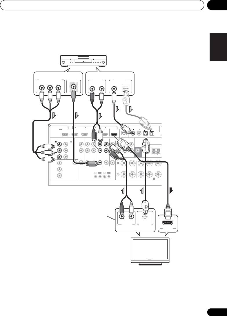
Connecting your equipment 03
Connecting your DVD player with no HDMI output
English
This diagram shows connections of a TV (with HDMI input) and DVD player (or other playback
component with no HDMI output) to the receiver.
Deutsch
Français
HDMI
ASSIGNABLE
ASSIGNABLE
ASSIGNABLE
Italiano
(
DVD
)
(
DVR/BDR
)
ASSIGNABLE
(
DVD
)
L
Y
Y
P
B
P
B
R
P
R
P
R
FRONT CENTER SURROUND
R
LR
Y
Nederlands
P
B
P
R
Español
• If you want to listen to the sound of the TV over the receiver, connect the receiver and TV with
audio cables.
• If the connection was made using an optical cable, you’ll need to tell the receiver which digital
input you connected the DVD player to (see The Input Setup menu on page 42).
27
En
L
(
OUTPUT
(
DVR/BDR
)
ZONE 2
DVR/BDR
DVD
TV/SAT
VIDEO
CD
CD-R/TAPE
OUT
OUT IN
IN
IN
IN
OUT ININ
5
OPTICAL
A
(
CD
)
(
TV/SAT
)
COMPONENT VIDEO
AUDIO
PRE OUT
ANTENNA
SUBWOOFER
AM LOOP
F
D
BD IN IN IN IN IN
1
2 3 4
OUT
LAN
COAXIAL
1 4
(
10/100
)
IN
1
IN
2
IN
1
IN
2
IN
1
IN
2
MONITOR
OUT
VIDEO
IR CONTROL
IN
OUT
IN
OUT
SPEAKERS
A
COMPONENT VIDEO OUT
VIDEO OUT
AUDIO OUT
DIGITAL OUT
PR
P
B
Y
RL
ANALOG
COAXIAL OPTICAL
RL
ANALOG
OPTICAL
AUDIO OUT
DIGITAL OUT
HDMI IN
DVD player etc.
Select one
Select one
VSX-1020/
VSX-1025
This connection is
required in order to
listen to the sound of
the TV over the receiver.
Select one
HDMI/DVI-compatible TV
VSX-1020_SYXCN.book 27 ページ 2010年3月12日 金曜日 午前9時10分
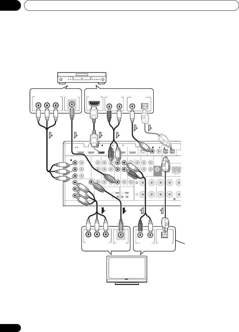
Connecting your equipment03
Connecting your TV with no HDMI input
This diagram shows connections of a TV (with no HDMI input) and DVD player (or other playback
component) to the receiver.
• With these connections, the picture is not output to the TV even if the DVD player is connected with
an HDMI cable. Connect the DVD player’s video signals using a composite or component cord.
HDMI
ASSIGNABLE
ASSIGNABLE
ASSIGNABLE
(
OUTP
(
DVD
)
(
DVR/BDR
)
ASSIGNABLE
DVD
(
)
(
DVR/BDR
)
L
Y
Y
PB
P
B
R
ZONE 2
DVR/BDR
DVD
TV/SAT
VIDEO
CD
CD-R/TAPE
PR
PR
OUT
OUT IN
IN
IN
IN
OUT ININ
FRONT CENTER SURROUND
R
LR
Y
P
B
PR
• Connect using an HDMI cable to listen to HD audio on the receiver. Do not use an HDMI cable
to input video signals.
Depending on the video component, it may not be possible to output signals connected by
HDMI and other methods simultaneously, and it may be necessary to make output settings.
Please refer to the operating instructions supplied with your component for more information.
28
En
U
COMPONENT VIDEO OUT
VIDEO OUT
HDMI OUT
AUDIO OUT
DIGITAL OUT
PR
P
B
Y
RL
ANALOG
COAXIAL OPTICAL
BD IN IN IN IN IN
1
2 3 4
OUT
LAN
COAXIAL
OPTICAL
1 4
(
10/100
)
IN
1
IN
2
IN
1
IN
2
(
CD
)
(
TV/SAT
)
COMPONENT VIDEO
AUDIO
PRE OUT
IN
1
IN
2
ANTENNA
SUBWOOFER
AM LOOP
MONITOR
OUT
VIDEO
IR CONTROL
IN
OUT
IN
OUT
SPEAKERS
A
PR
P
B
Y
RL
ANALOG
OPTICAL
COMPONENT VIDEO IN
VIDEO IN
AUDIO OUT
DIGITAL OUT
DVD player etc.
Select one
Select one
VSX-1020/
VSX-1025
This connection is
required in order to
Select one
listen to the sound of
Select one
the TV over the receiver.
TV
VSX-1020_SYXCN.book 28 ページ 2010年3月12日 金曜日 午前9時10分
• If the connection was made
using an optical cable, you’ll
need to tell the receiver which
digital input you connected
the DVD player to (see The
Input Setup menu on page 42).
Connecting your equipment 03
English
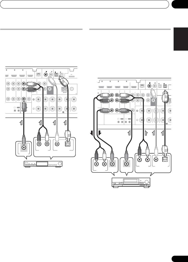
Connecting a satellite/cable
Connecting a HDD/DVD
receiver or other set-top box
recorder, VCR and other video
Satellite and cable receivers, and terrestrial
sources
digital TV tuners are all examples of so-called
This receiver has two sets of audio/video
‘set-top boxes’.
inputs and outputs suitable for connecting
Deutsch
analog or digital video devices, including
HDD/DVD recorders and VCRs.
ASSIGNABLE
ASSIGNABLE
(
DVD
)
(
DVR/BDR
)
Français
FRONT CENTER SURROUND
SURRO
R
Italiano
Nederlands
Español
• If the connection was made using a coaxial
cable, you’ll need to tell the receiver which
digital input you connected the set-top box
to (see The Input Setup menu on page 42).
• If the connection was made using a coaxial
cable, you’ll need to tell the receiver which
digital input you connected the recorder to
(see The Input Setup menu on page 42).
• In order to record, you must connect the
analog audio cables (the digital connection
is for playback only).
29
En
U
(
OUTPUT 5 V 100 mA MA
DVR/BDR
DVD
TV/SAT
VIDEO
CD
CD-R/TAPE
OUT IN
IN
IN
IN
OUT ININ
LR LR
X
OPTICAL
ADAPTER PO
(
CD
)
(
TV/SAT
)
PRE OUT
ANTENNA
SUBWOOFER
AM LOOP
FM UNBAL 75
R
LAN
COAXIAL
IR CONTROL
SPEAKERS
N
2 3 4
IN IN
OUT
(
10/100
)
IN
1
IN
2
IN
1
IN
2
IN
OUT
IN
OUT
A
RL
ANALOG
COAXIAL OPTICAL
AUDIO OUT
DIGITAL OUT
VIDEO OUT
VSX-1020/VSX-1025
Select one
STB
ASSIGNABLE
ASSIGNABL
E
(
DVD
)
(
DVR/BDR
)
B
R
Y
(
OUT
R/BDR
)
L
R
ZONE 2
DVR/BDR
DVD
TV/SAT
VIDEO
CD
CD-R/TAPE
OUT
OUT IN
IN
IN
IN
OUT ININ
FRONT CENTER SURROUND
R
LR
P
OPTICAL
(
CD
)
(
TV/SAT
)
AUDIO
PRE OUT
ANTENNA
SUBWOOFER
AM LOOP
D
EO
IR CONTROL
SPEAKERS
R
IN IN IN IN
1
2 3 4
OUT
LAN
COAXIAL
(
10/100
)
IN
1
IN
2
IN
1
IN
2
2
IN
OUT
IN
OUT
A
RL
ANALOG
COAXIAL OPTICAL
AUDIO OUT
DIGITAL OUT
RL
ANALOG
AUDIO IN
VIDEO IN
VIDEO OUT
VSX-1020/VSX-1025
Select one
HDD/DVD recorder, VCR, etc.
VSX-1020_SYXCN.book 29 ページ 2010年3月12日 金曜日 午前9時10分
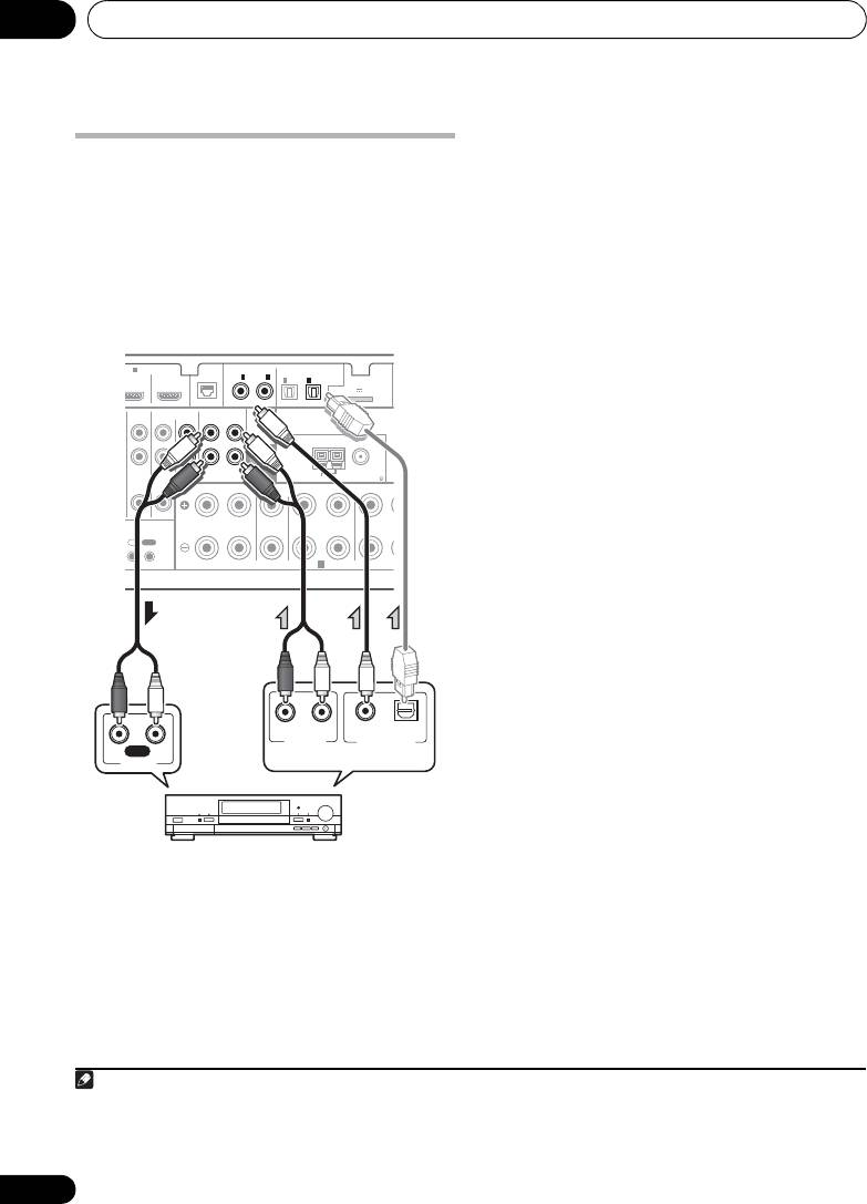
Connecting your equipment03
• If your turntable has line-level outputs (i.e.,
Connecting other audio
it has a built-in phono pre-amp), connect it
to the CD inputs instead.
components
• If you’re connecting a recorder, connect
This receiver has both digital and analog
the analog audio outputs to the analog
inputs, allowing you to connect audio
audio inputs on the recorder.
components for playback.
One of these inputs have corresponding outputs
About the WMA9 Pro decoder
for use with analog audio recorders.
This unit has an on-board Windows Media™
1
Audio 9 Professional
(WMA9 Pro) decoder, so
it is possible to playback WMA9 Pro-encoded
ASSIGNABLE
ASSIGNABLE
audio using HDMI, coaxial or optical digital
(
DVD
)
(
DVR/BDR
)
connection when connected to a WMA9 Pro-
compatible player. However, the connected
DVD player, set-top box, etc. must be able to
output WMA9 Pro format audio signals
FRONT CENTER SURROUND
SURROUN
R
through a coaxial or optical digital output.
• If the connection was made using an
optical cable, you’ll need to tell the receiver
which digital input you connected the
component to (see The Input Setup menu
on page 42).
30
En
D
IN
4
OUT
LAN
COAXIAL
OPTICAL
10/100
(
)
IN
1
IN
2
IN
1
IN
2
ADAPTER PORT
(
OUTPUT 5 V 100 mA MAX
)
CD
(
)
(
TV/SAT
)
PRE OUT
ANTENNA
TV/SAT
VIDEO
CD
CD-R/TAPE
SUBWOOFER
IN
IN
IN
OUT IN
AM LOOP
FM UNBAL 75
LR LR
CONTROL
IN
OUT
SPEAKERS
A
RL
ANALOG
COAXIAL OPTICAL
AUDIO OUT
DIGITAL OUT
RL
REC
AUDIO IN
VSX-1020/VSX-1025
Select one
CD-R, MD, DAT, etc.
Note
VSX-1020_SYXCN.book 30 ページ 2010年3月12日 金曜日 午前9時10分
1• Windows Media and the Windows logo are trademarks or registered trademarks of Microsoft Corporation in the United
States and/or other countries.
• With WMA9 Pro, sound problems may occur depending on your computer system. Note that WMA9 Pro 96 kHz
sources will be downsampled to 48 kHz.
Connecting your equipment 03
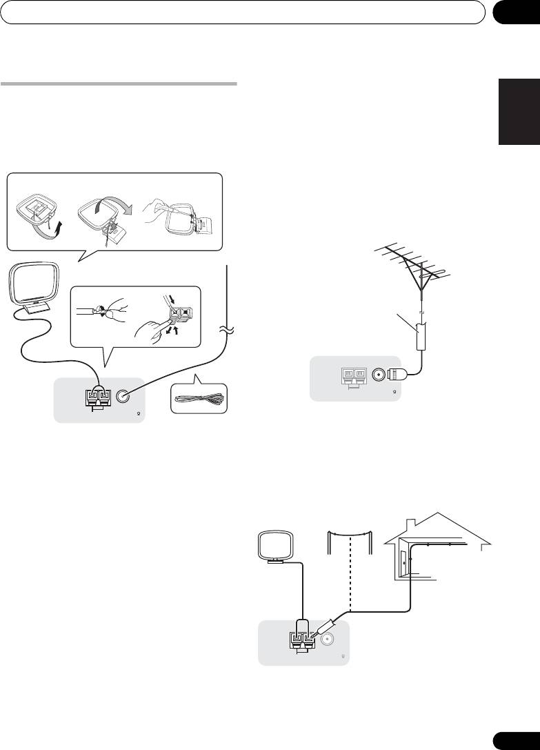
4 Place the AM antenna on a flat surface
English
Connecting AM/FM antennas
and in a direction giving the best reception.
Connect the AM loop antenna and the FM wire
5 Connect the FM wire antenna into the FM
antenna as shown below. To improve reception
antenna socket.
and sound quality, connect external antennas
For best results, extend the FM antenna fully
(see Connecting external antennas below).
and fix to a wall or door frame. Don’t drape
Deutsch
loosely or leave coiled up.
fig. a fig. b fig. c
Connecting external antennas
To improve FM reception connect an external
FM antenna to FM UNBAL 75 Ω.
Français
3
1
2
4
Italiano
5
ANTENNA
Nederlands
AM LOOP
FM UNBAL 75
To improve AM reception, connect a 5 m to 6 m
length of vinyl-coated wire to the AM LOOP
1 Pull off the protective shields of both AM
terminals without disconnecting the supplied
antenna wires.
AM loop antenna.
Español
2 Push open the tabs, then insert one wire
For the best possible reception, suspend
fully into each terminal, then release the tabs
horizontally outdoors.
to secure the AM antenna wires.
3 Fix the AM loop antenna to the attached
stand.
To fix the stand to the antenna, bend in the
direction indicated by the arrow (fig. a) then
clip the loop onto the stand (fig. b).
• If you plan to mount the AM antenna to a
wall or other surface, secure the stand with
screws (fig. c) before clipping the loop to
the stand. Make sure the reception is clear.
31
En
ANTENNA
AM LOOP
FM UNBAL 75
75 Ω coaxial cable
ANTENNA
AM LOOP
FM UNBAL 75
Outdoor
antenna
Indoor antenna
(vinyl-coated wire)
5 m to 6 m
VSX-1020_SYXCN.book 31 ページ 2010年3月12日 金曜日 午前9時10分
Connecting your equipment03
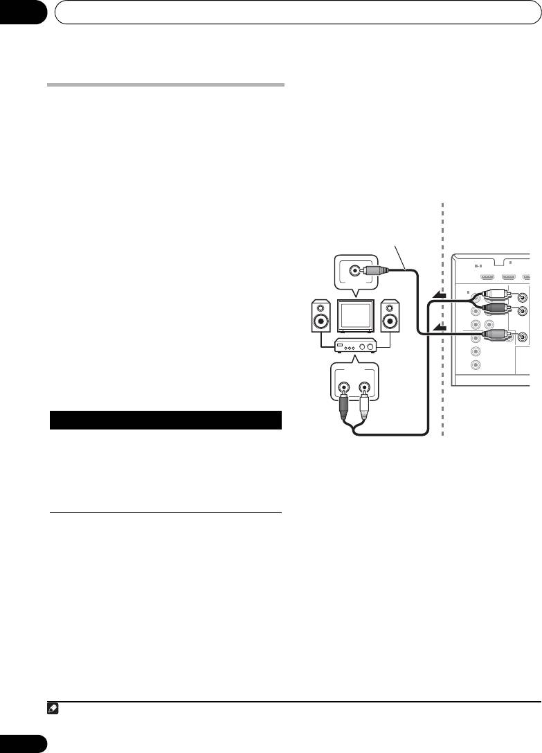
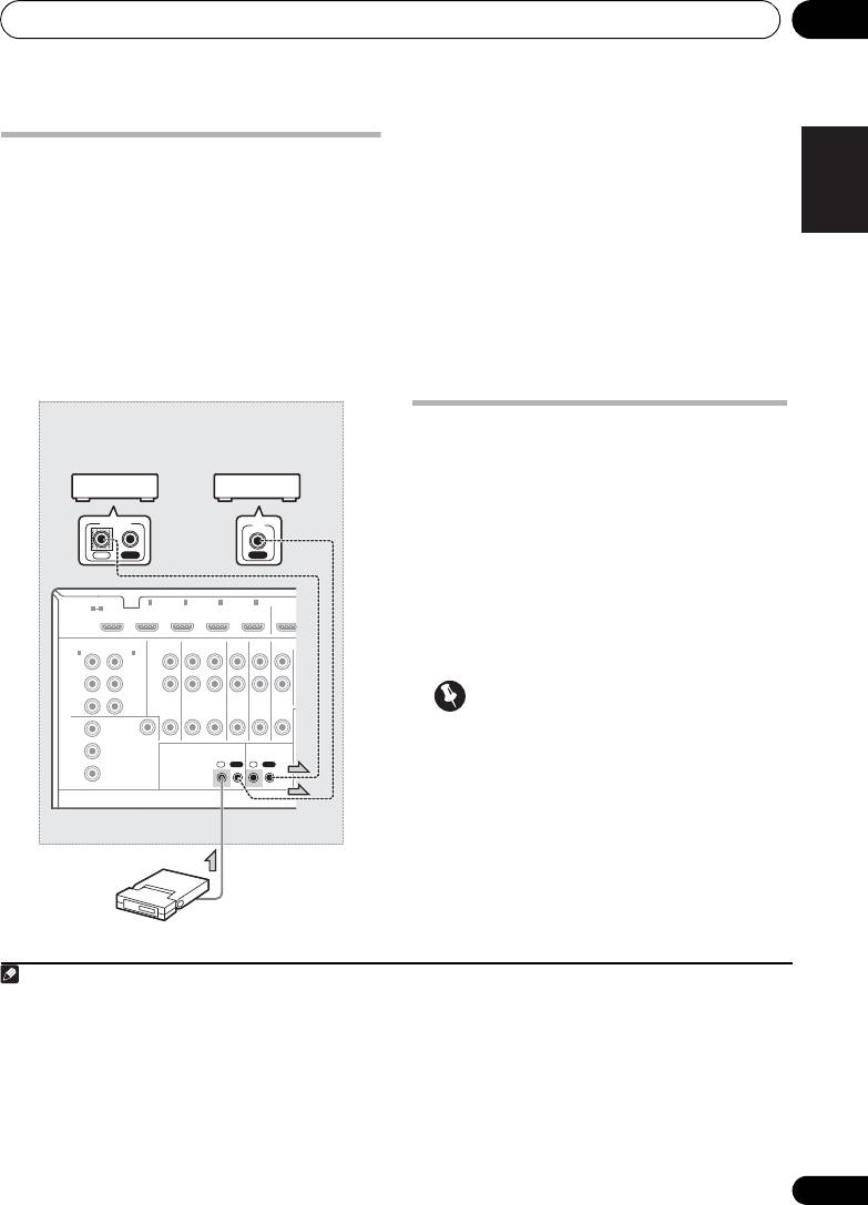
Basic MULTI-ZONE setup (ZONE 2)
MULTI-ZONE setup
1 Connect a separate amplifier to the
This receiver can power up to two independent
1
AUDIO ZONE 2 OUT
jacks and a TV monitor
systems in separate rooms after you have
to the
VIDEO ZONE 2 OUT
jack, both on this
made the proper MULTI-ZONE connections.
receiver.
Different sources can be playing in two zones
2 Connect a pair of speakers to the sub
at the same time or, depending on your needs,
zone amplifier.
the same source can also be used. The main
and sub zone have independent power (the
main zone power can be off while sub zone is
on) and the sub zone can be controlled by the
remote or front panel controls.
Making MULTI-ZONE connections
It is possible to make these connections if you
1
have a separate speakers and TV monitor
for
the sub zone (ZONE 2). You will also need a
separate amplifier if you are not using the
MULTI-ZONE setup using speaker terminals
(ZONE 2) on page 33 for the sub zone.
MULTI-ZONE listening options
The following table shows the signals that can
be output to ZONE 2:
32
En
Note
HDMI
BD IN IN IN
1
ASSIGNABLE
1 4
VIDEO IN
COMPONENT VIDEO
AUDIO
IN
1
ASSIGNABLE
IN
2
DVD
(
)
(
DVR
)
L
Y
Y
P
B
P
B
R
ZONE 2
P
R
P
R
OUT
MONITOR
Y
OUT
VIDEO
P
B
P
R
AUDIO IN
RL
Sub Zone Input functions available
a
ZONE 2 DVD, TV/SAT, DVR/BDR, VIDEO
,
b
a
VIDEO1/2
, INTERNET RADIO
, iPod/
a
USB
, CD, CD-R/TAPE, TUNER,
ADAPTER PORT
(Outputs analog audio and composite
video.)
a.VSX-1020/VSX-1025 only.
b.VSX-920 only.
1 VSX-920 model cannot connect the TV monitor for sub zone.
Sub zone
Main zone
VSX-1020/VSX-1025 only
VSX-1020/VSX-1025
VSX-1020_SYXCN.book 32 ページ 2010年3月12日 金曜日 午前9時10分
Connecting your equipment 03
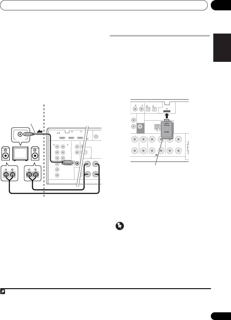
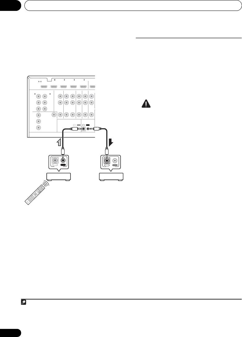
MULTI-ZONE setup using speaker
English
terminals (ZONE 2)
Connecting Optional
Bluetooth
You must select ZONE 2 in Speaker system
ADAPTER
setting on page 101 to use this setup.
When the Bluetooth ADAPTER (Pioneer Model
1 Connect a pair of speakers to the
No. AS-BT100) is connected to this receiver, a
surround back speaker terminals on this
product equipped with Bluetooth wireless
Deutsch
receiver.
technology (portable cell phone, digital music
player, etc.) can be used to listen to music
2
VSX-1020/VSX-1025 only:
Connect a TV
1
wirelessly.
monitor to the
VIDEO ZONE 2 OUT
jacks on
this receiver.
Français
Italiano
Nederlands
• Switch the receiver into standby and
connect
Bluetooth
ADAPTER to the
ADAPTER PORT
.
• For instructions on playing the contents of
Bluetooth wireless technology device, see
Español
Bluetooth® ADAPTER for Wireless
Enjoyment of Music on page 53.
Important
• Do not move the receiver with the
Bluetooth ADAPTER connected. Doing so
could cause damage or faulty contact.
33
En
AL
ABLE
SIRIU
ADAPTER PORT
IN
OUTPUT 5 V 500 mA MAX
)
OP
FM UNBAL 75
D
L RL
SURROUND BACK
(
Single
)
HDMI
BD IN IN IN
1
2
ASSIGNABLE
1 4
COMPONENT VIDEO
IN
1
ASSIGNABLE
AUDIO
IN
2
(
DVD
)
(
DVR/BDR
)
L
Y
Y
P
B
P
B
R
ZONE 2
DVR
P
R
P
R
OUT
OUT
MONITOR
Y
OUT
VIDEO
P
B
P
R
VIDEO IN
RL
Sub zone
Main zone
VSX-1020/VSX-1025 only
VSX-1020/VSX-1025
Note
1• The Bluetooth wireless technology enabled device must supports A2DP profiles.
• Pioneer does not guarantee proper connection and operation of this unit with all Bluetooth wireless technology
enabled devices.
COAXIAL
ASSIGNABLE
OPTICAL
IN
1
IN
2
ASSIGNABLE
IN
1
IN
2
ADAPTER PORT
(
OUTPUT 5 V 100 mA MAX
)
(
DVD
)
(
CD
)
(
TV/SAT
)
(
DVR/BDR
)
PRE OUT
ANTENNA
TAPE
SUBWOOFER
IN
AM LOOP
FM UNBAL 75
ONT CENTER SURROUND
SURROUND BACK
LR LR L
(
Single
)
FRO
SPEAKERS
A
VSX-1020/VSX-1025
Bluetooth
® ADAPTER
VSX-1020_SYXCN.book 33 ページ 2010年3月12日 金曜日 午前9時10分
Connecting your equipment03
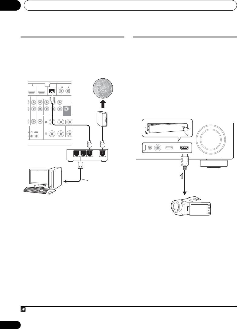
Connecting to the network
Connecting an HDMI-equipped
through LAN interface
component to the front panel
By connecting this receiver to the network via
input
the LAN terminal, you can listen to Internet
(VSX-1020/VSX-1025 only)
1
radio stations.
There is an HDMI input terminal on the front
panel. High quality pictures can be viewed via
the receiver simply by connecting an HDMI-
equipped video camera with a single HDMI
cable. HDMI-equipped components other than
video cameras can also be connected to this
terminal.
Connect the LAN terminal on this receiver to
the LAN terminal on your router (with or
without the built-in DHCP server function) with
a straight LAN cable (CAT 5 or higher).
Turn on the DHCP server function of your
router. In case your router does not have the
built-in DHCP server function, it is necessary to
set up the network manually. For details, see
Network Setup menu on page 104.
LAN terminal specifications
LAN terminal . . . . . . . . . . . . . . . . . . Ethernet jack
10BASE-T/100BASE-TX
34
En
Note
ASSIGNABLE
(
DVD
)
FRONT CENT
R
1 To listen to Internet radio stations, you must sign a contract with an ISP (Internet Service Provider) beforehand.
E
L
D
IN
4
OUT
LAN
COAXIAL
(
10/100
)
IN
1
IN
2
(
CD
)
PRE OUT
TV/SAT
VIDEO
CD
CD-R/TAPE
SUBWOOFER
IN
IN
IN
OUT IN
CONTROL
I
T
IN
OUT
LAN
321
WAN
Internet
Modem
VSX-1020/VSX-1025
Router
LAN cable
(sold separately)
to LAN port
PC
CONTROL ON
/
OFF
MASTER
VOLUME
VIDEO CAMERA
iPod
iPhone
MCACC
SETUP MIC
USB HDMI 5
Video camera, etc.
VSX-1020_SYXCN.book 34 ページ 2010年3月12日 金曜日 午前9時10分
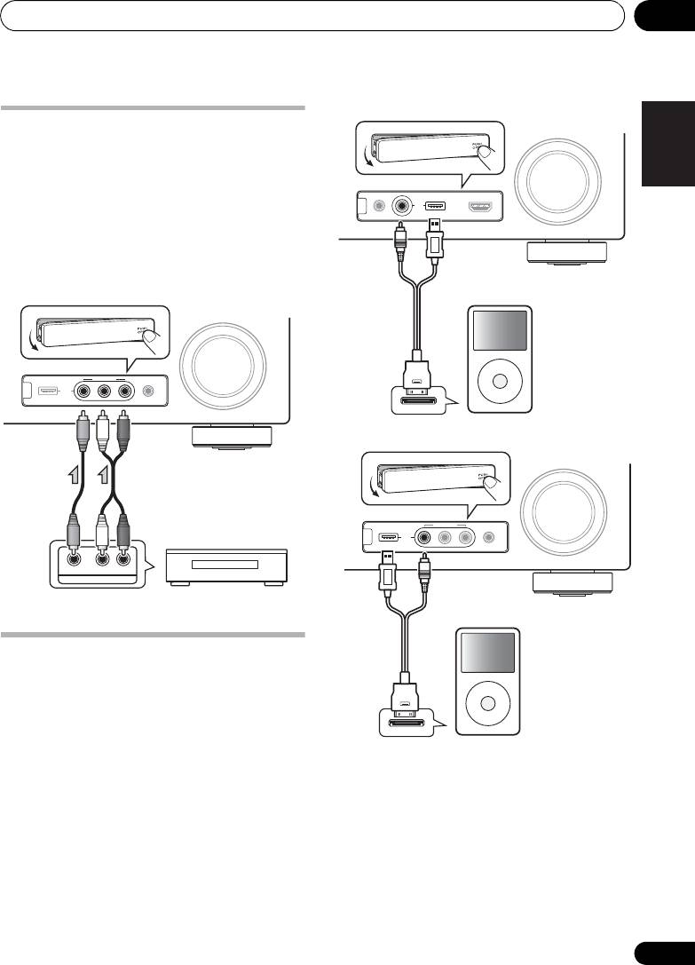
Connecting your equipment 03
VSX-1020/VSX-1025:
English
Connecting to the front panel
video terminal
(VSX-920 only)
Front video connections are accessed via the
INPUT SELECTOR dial (front panel) or INPUT
Deutsch
SELECT buttons (remote control). There are
standard audio/video jacks. Hook them up the
same way you made the rear panel
connections.
Français
CONTROL ON
/
OFF
MASTER
VOLUME
VIDEO INPUT
iPod
iPhone
USB
MCACC
AUDIOLRVIDEO
SETUP MIC
Italiano
VSX-920:
Nederlands
AUDIOVIDEO
OUTPUT
Español
Connecting an iPod
This receiver has a dedicated iPod terminal
that will allow you to control playback of audio
content from your iPod using the controls of
this receiver.
• Switch the receiver into standby then use
the supplied iPod cable to connect your iPod
to the iPod/iPhone/USB terminal on the front
panel of this receiver.
• It is also possible to connect using the
cable included with the iPod, but in this
case it is not possible to view pictures via
the receiver.
• For the cable connection, also refer to the
operating instructions for your iPod.
35
En
TV game, video camera, etc.
CONTROL ON
/
OFF
MASTER
VOLUME
VIDEO CAMERA
iPod
iPhone
MCACC
SETUP MIC
USB HDMI 5
MENU
iPod cable
(supplied)
iPod
CONTROL ON
/
OFF
MASTER
VOLUME
VIDEO INPUT
iPod
iPhone
USB
MCACC
AUDI OLRVIDEO
SETUP MIC
MENU
iPod cable
(supplied)
iPod
VSX-1020_SYXCN.book 35 ページ 2010年3月12日 金曜日 午前9時10分
Connecting your equipment03
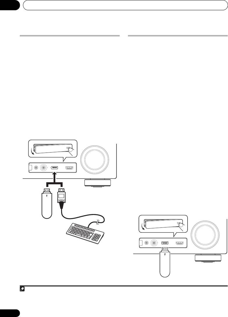
Connecting a USB device
Connecting a USB device for
It is possible to play audio and photo files by
Advanced MCACC output
connecting USB devices to this receiver. It is
When using Auto MCACC (
page 87
) or Acoustic
also possible to connect a USB keyboard (US-
Calibration EQ Professional (
page 93
) to
international layout) to the receiver to enter text
calibrate the reverb characteristics of your
in the following GUI screens.
listening room, the 3D graphs of the reverb
• Change the input name in the Input Setup
characteristics in your listening room (before and
menu (page 43).
after calibration) can be checked on a computer
• Add names to radio station presets
screen.
(page 51).
The various MCACC parameters can also be
• Enter Internet radio station URLs
(page 55)
.
checked on the computer. MCACC data and
parameters are transferred from this receiver
• Switch the receiver into standby then
to a USB device and by connecting the USB
connect your USB device to the iPod/iPhone/
device to a computer, the data is imported via
USB terminal on the front panel of this
the MCACC software in the computer.
1
receiver.
The MCACC software to output the results is
available from the support area of the Pioneer
website (http://www.pioneer.eu). Instructions
for using the software are also available here. If
you have any questions about the software,
please contact the Pioneer Service Center
specified on your warranty card.
See the documentation provided with the
Advanced MCACC PC Display Application
Software for more information.
• For the USB device connection and
operations, see Output MCACC data on
2
page 97.
36
En
Note
1 This receiver does not support a USB hub.
CONTROL ON
/
OFF
MASTER
VOLUME
VIDEO CAMERA
iPod
iPhone
MCACC
SETUP MIC
USB HDMI 5
VSX-1020/VSX-1025
USB mass
storage device
USB keyboard
CONTROL ON
/
OFF
MASTER
VOLUME
VIDEO CAMERA
iPod
iPhone
MCACC
SETUP MIC
USB HDMI 5
2 The various parameters and the reverb characteristics data used for display on the computer are not cleared when
the power is turned off (see Output MCACC data on page 97).
VSX-1020/VSX-1025
USB mass
storage device
VSX-1020_SYXCN.book 36 ページ 2010年3月12日 金曜日 午前9時10分
Connecting your equipment 03
2 Connect the
IR IN
jack of another
English
Connecting an IR receiver
component to the
IR OUT
jack on the rear of
this receiver to link it to the IR receiver.
If you keep your stereo components in a closed
Please see the manual supplied with your IR
cabinet or shelving unit, or you wish to use the
receiver for the type of cable necessary for the
sub zone remote control in another zone, you
connection.
can use an optional IR receiver (such as a Niles
Deutsch
or Xantech unit) to control your system instead
• If you want to link a Pioneer component to
of the remote sensor on the front panel of this
the IR receiver, see Operating other Pioneer
1
receiver.
components with this unit’s sensor below
to connect to the CONTROL jacks instead
1 Connect the IR receiver sensor to the
IR IN
of the IR OUT jack.
jack on the rear of this receiver.
Français
Operating other Pioneer
components with this unit’s
sensor
Many Pioneer components have
SR CONTROL
Italiano
jacks which can be used to link components
together so that you can use just the remote
sensor of one component. When you use a
remote control, the control signal is passed
along the chain to the appropriate
Nederlands
2
component.
Important
• Note that if you use this feature, make sure
that you also have at least one set of analog
Español
audio, video or HDMI jacks connected to
another component for grounding
purposes.
1 Decide which component you want to
use the remote sensor of.
When you want to control any component in
the chain, this is the remote sensor at which
you’ll point the corresponding remote control.
37
En
Note
CONTROL
IR
IN OUT
IN
HDMI
BD IN IN IN IN IN
1
2 3 4
OUT
ASSIGNABLE
1 4
COMPONENT VIDEO
ASSIGNABLE
AUDIO
IN
1
IN
2
(
DVD
)
(
DVR/BDR
)
L
Y
Y
PB
P
B
R
ZONE 2
DVR/BDR
DVD
TV/SAT
VIDEO
PR
PR
OUT
OUT IN IN
IN
IN
MONITOR
Y
OUT
VIDEO
P
B
IR CONTROL
IN
OUT
IN
OUT
PR
1 • Remote operation may not be possible if direct light from a strong fluorescent lamp is shining on the IR receiver
remote sensor window.
• Note that other manufacturers may not use the IR terminology. Refer to the manual that came with your component
to check for IR compatibility.
• If using two remote controls (at the same time), the IR receiver’s remote sensor takes priority over the remote sensor
on the front panel.
Closet or shelving unit
Pioneer
Non-Pioneer
component
component
VSX-1020/VSX-1025
IR receiver
VSX-1020_SYXCN.book 37 ページ 2010年3月12日 金曜日 午前9時10分
2 • If you want to control all your components using this receiver’s remote control, see Setting the remote to control
other components on page 77.
• If you have connected a remote control to the CONTROL IN jack (using a mini-plug cable), you won’t be able to con-
trol this unit using the remote sensor.
Connecting your equipment03
2 Connect the
CONTROL OUT
jack of that
component to the
CONTROL IN
jack of
Plugging in the receiver
another Pioneer component.
Only plug in after you have connected all your
Use a cable with a mono mini-plug on each
components to this receiver, including the
end for the connection.
speakers.
1 Plug the supplied power cord into the
AC
HDMI
BD IN IN IN IN IN
1
2 3 4
OUT
ASSIGNABLE
1 4
IN
socket on the back of the receiver.
1
2 Plug the other end into a power outlet.
COMPONENT VIDEO
ASSIGNABLE
AUDIO
IN
1
IN
2
(
DVD
)
(
DVR/BDR
)
L
Y
Y
PB
P
B
R
ZONE 2
DVR/BDR
DVD
TV/SAT
VIDEO
CAUTION
PR
PR
OUT
OUT IN IN
IN
IN
MONITOR
• Handle the power cord by the plug part. Do
Y
OUT
VIDEO
not pull out the plug by tugging the cord,
P
B
IR CONTROL
IN
OUT
IN
OUT
and never touch the power cord when your
PR
hands are wet, as this could cause a short
circuit or electric shock. Do not place the
unit, a piece of furniture, or other object on
the power cord or pinch the cord in any
other way. Never make a knot in the cord or
tie it with other cables. The power cords
IN OUT
IN OUT
CONTROL
CONTROL
should be routed so that they are not likely
to be stepped on. A damaged power cord
can cause a fire or give you an electric
shock. Check the power cord once in a
while. If you find it damaged, ask your
nearest Pioneer authorized independent
service company for a replacement.
Continue the chain in the same way for as
• Do not use any power cord other than the
many components as you have.
one supplied with this unit.
• Do not use the supplied power cord for any
purpose other than that described below.
• The receiver should be disconnected by
removing the mains plug from the wall
socket when not in regular use, e.g., when
on vacation.
38
En
VSX-1020/VSX-1025
Note
VSX-1020_SYXCN.book 38 ページ 2010年3月12日 金曜日 午前9時10分
1 After this receiver is connected to an AC outlet, a 2 second to 10 second HDMI initialization process begins. You
cannot carry out any operations during this process. The HDMI indicator in the front panel display blinks during this
process, and you can turn on this receiver once it has stopped blinking. When you set the Control to OFF, you can
skip this process. For details about the Control with HDMI function, see Control with HDMI function on page 63.
Оглавление
- Contents
- Flow of settings on the receiver
- Before you start
- Controls and displays
- Connecting your equipment
- Basic Setup
- Basic playback
- Listening to your system
- Control with HDMI function
- Using other functions
- Controlling the rest of your system
- The Advanced MCACC menu
- The System Setup and Other Setup menus
- Additional information
- Table des matières
- Organigramme des réglages sur le récepteur
- Avant de commencer
- Commandes et affichages
- Raccordement de votre équipement
- Configuration de base
- Lecture de base
- Écoute de sources à l’aide de votre système
- Fonction Control HDMI
- Utilisation d’autres fonctions
- Commander le reste de votre système
- Le menu MCACC avancé
- Configuration du système et autres réglages
- Informations complémentaires
- Содержание
- Порядок выполнения настроек на ресивере
- Перед началом работы
- Органы управления и индикаторы
- Подключение оборудования
- Основная настройка
- Основные операции воспроизведения
- Прослушивание системы
- Функция Управление по HDMI
- Использование других функций
- Управление остальными частями системы
- Меню Advanced MCACC
- Меню System Setup (Настройка системы) и Other Setup (Другие настройки)
- Дополнительная информация
