Pioneer PLASMA DISPLAY: Part Names and Function
Part Names and Function: Pioneer PLASMA DISPLAY
English
Part Names and Function
5
En
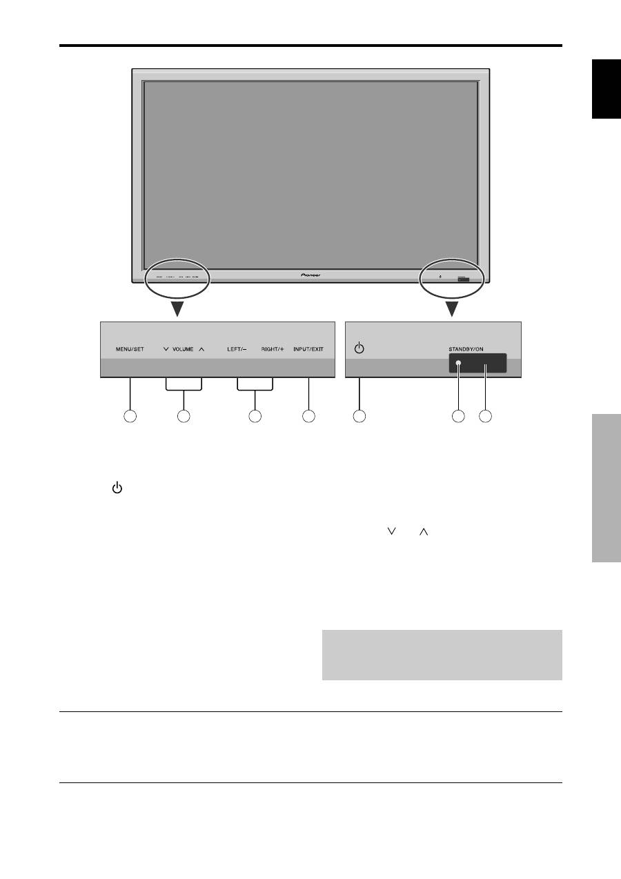
q
Power (
)
Turns the monitor’s power on and off.
w
Remote sensor window
Receives the signals from the remote control.
e
STANDBY/ON indicator
When the power is on ............................. Lights green.
When the power is in the standby mode ... Lights red.
r
INPUT/EXIT
Switches the input.
The available inputs depend on the setting of “BNC
INPUT”, “RGB SELECT”, “D-SUB SELECT” and
“DVI SET-UP”.
Functions as the EXIT buttons in the On-Screen
Display (OSD) mode.
Front View
4
5
6
7
1
3
2
t
LEFT/– and RIGHT/+
Functions as the CURSOR (
/
) buttons in the On-
Screen Display (OSD) mode.
y
VOLUME
and
Adjusts the volume. Functions as the CURSOR (
▲
/
▼
) buttons in the On-Screen Display (OSD) mode.
u
MENU/SET
Sets the On-Screen Display (OSD) mode and displays
the main menu.
WARNING
The Power on/off switch does not disconnect the plasma
display completely from the supply mains.
Part Names and Function
Note:
This plasma monitor has the capasity to display images when connected to European DVD players with a SCART
output signal, which is RGB with composite sync.
Your dealer can supply a special SCART cable, which will enable you to use the RGB with composite sync signal.
To obtain the special cable as well as for further information, please contact your dealer.
Please refer to page 19 for selection of the correct mode in the on-screen display.
English
Part Names and Function
6
En
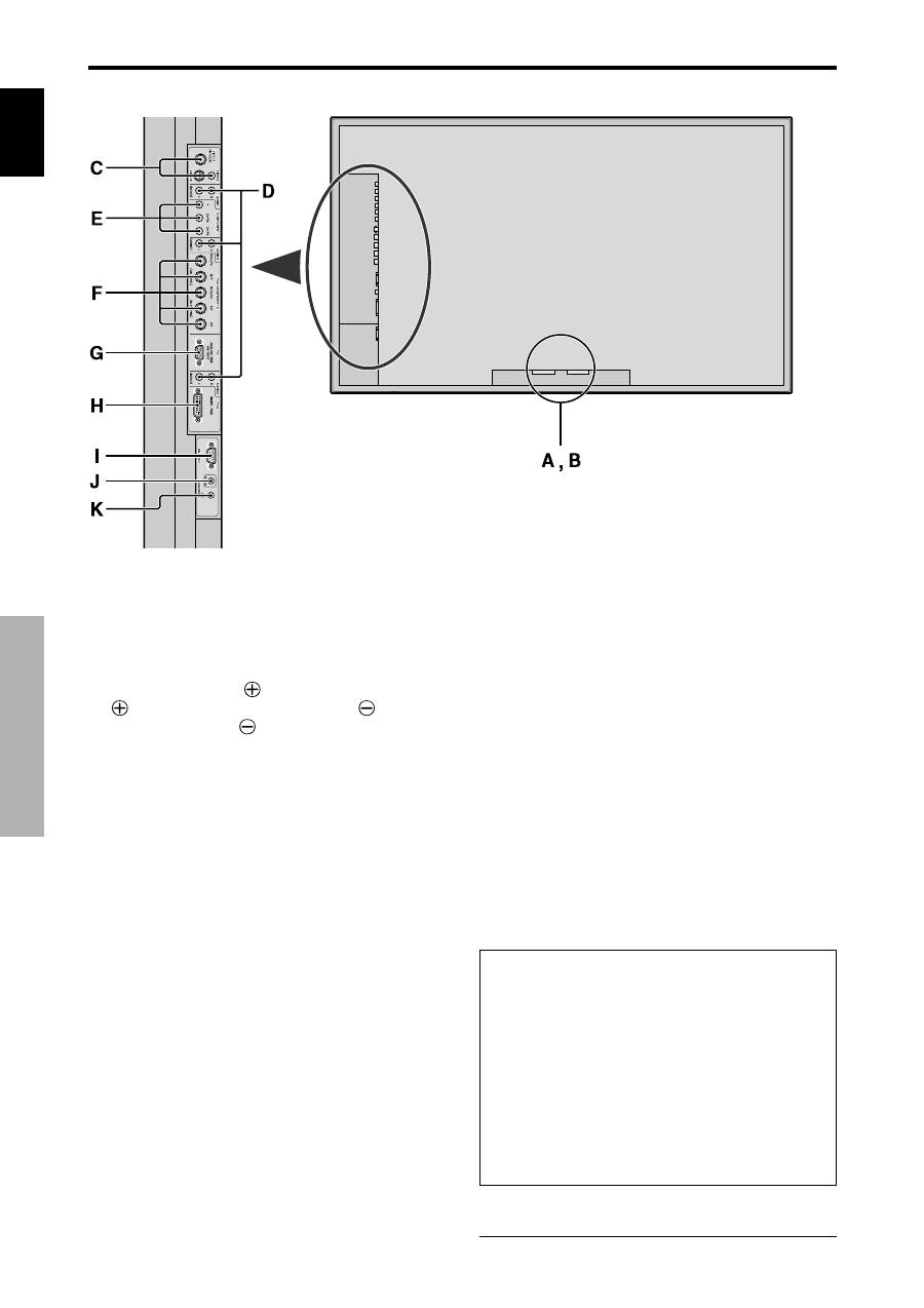
A
AC IN
Connect the included power cord here.
B
EXT SPEAKER L and R
Connect speakers (optional) here. Maintain the correct
polarity. Connect the
(positive) speaker wire to the
EXT SPEAKER terminal and the
(negative)
speaker wire to the
EXT SPEAKER terminal on
both LEFT and RIGHT channels.
Please refer to your speaker’s owner’s manual.
C
VIDEO1, 2, 3 (BNC, RCA, S-Video)
Connect VCR’s, DVD’s or Video Cameras, etc. here.
VIDEO1 can be used for Input or Output (see page
24).
D
AUDIO1, AUDIO2, AUDIO3
These are audio input terminals.
The input is selectable. Set which video image to allot
them from the SOUND menu screen.
E
COMPONENT1
Connect DVD’s, High Definition or Laser Discs, etc.
here.
F
PC2/COMPONENT2
PC2:
You can connect an analog RGB signal
and the syncronization signal.
COMPONENT2: You can connect DVDs, High
Definition sources, Laser Discs, etc.
here.
This input can be set for use with an
RGB or component source (see page
17).
G
PC1 (mini D-Sub 15pin)
Connect an analog RGB signal from a computer, etc.
here. This input can be used for Input or Output (see
page 24).
H
PC3
(DVI 24pin)
Connect a digital signal (TMDS) from a source with a
DVI output.
I
RS-232C
Never connect any component to this connector
without first consulting your Pioneer installation
technician.
This connector is used for plasma display setup
adjustments.
J
REMOTE IN
Connect the remote cable* to the remote control’s
remote jack to obtain wired remote control.
K
REMOTE OUT
Connect the remote cable* to the REMOTE IN jack of
the other display monitor to obtain wired remote
control.
Information
• For Y/CB/Cr, connect to the COMPONENT1 or PC2/
COMPONENT2 terminals.
• For SCART, this unit provides three ways to connect:
·
SCART1:
Connect R/G/B and composite sync. to
the PC2/COMPONENT2 terminals. (R, G, B and
HD connector)
·
SCART2:
Connect R/G/B to the COMPONENT2
terminals and composite sync. to the VIDEO1
terminal.
·
SCART3:
Connect R/G/B and composite sync. to
the PC1 terminal.
* The 1/8 Stereo Mini cable must be purchased separately.
Rear View/ Terminal Board
English
Part Names and Function
7
En
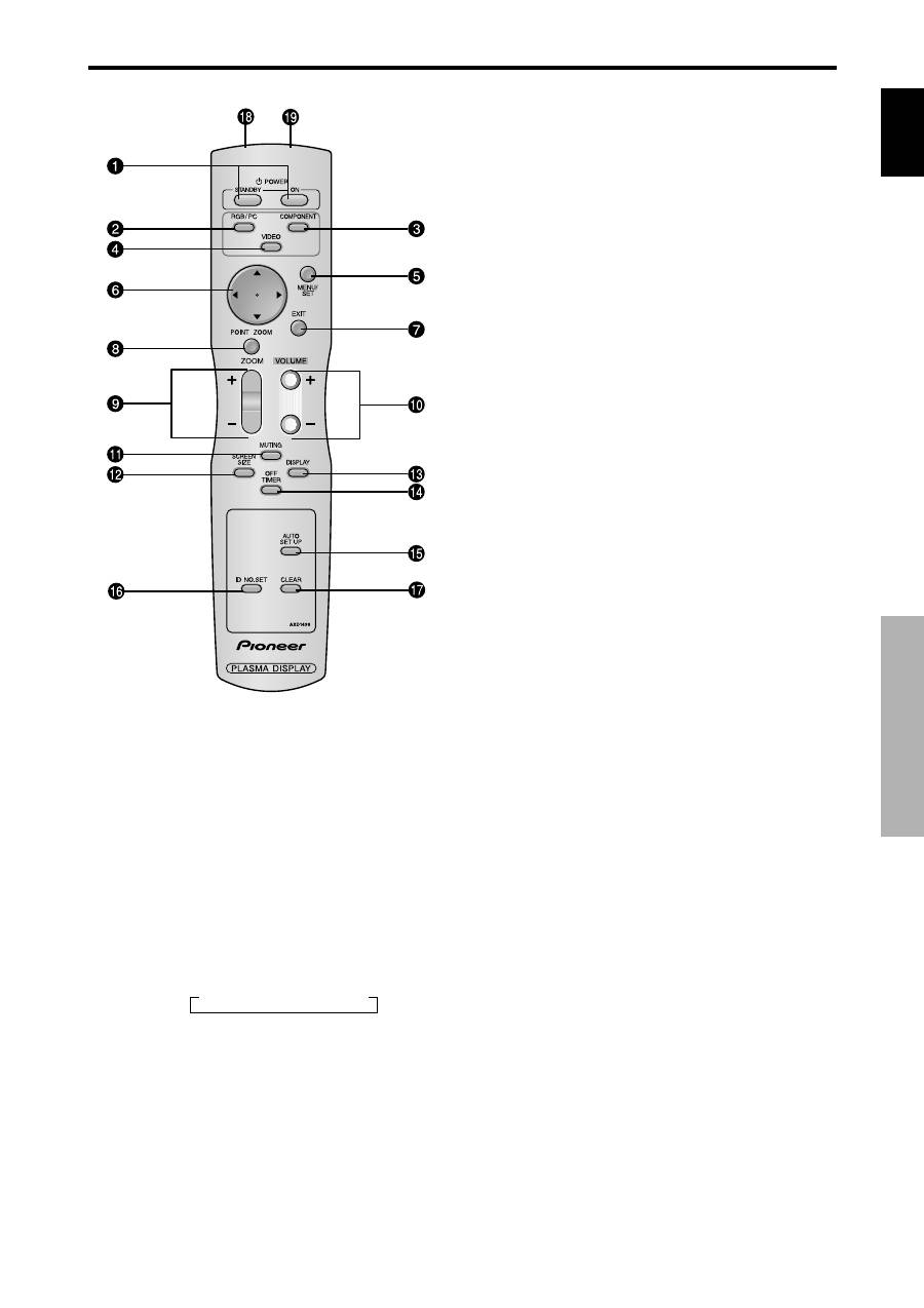
q
POWER ON/STANDBY
Switches the power on/standby.
(This does not operate when STANDBY/ON indicator
of the main unit is off.)
w
RGB/PC
Press this button to select RGB/PC as the source.
RGB/PC can also be selected using the INPUT/EXIT
button on the monitor.
e
COMPONENT
Press this button to select COMPONENT as the source.
COMPONENT can also be selected using the INPUT/
EXIT button on the monitor.
r
VIDEO
Press this button to select VIDEO as the source.
VIDEO can also be selected using the INPUT/EXIT
button on the monitor.
t
MENU/SET
Press this button to access the OSD controls.
Press this button during the display of the main menu
to go to the sub menu.
y
CURSOR (
▲
/
▼
/
/
)
Use these buttons to select items or settings and to
adjust settings.
u
EXIT
Press this button to exit the OSD controls in the main
menu. Press this button during the display of the sub
menu to return to the previous menu.
i
POINT ZOOM
Press this button to display the pointer.
o
ZOOM (+ /–)
Enlarges or reduces the image.
!0
VOLUME (+ /–)
Adjusts the sound volume.
!1
MUTING
Mutes the sound.
!2
SCREEN SIZE
Automatically detects the signal and sets the aspect ratio.
SCREEN SIZE button is not active for all signals.
!3
DISPLAY
Displays the source settings on the screen.
!4
OFF TIMER
Activates the off timer for the unit.
!5
AUTO SET UP
Press this button to adjust PHASE, CLOCK, Position,
and Contrast automatically, or to switch the screen size
to ZOOM mode automatically with the superimposed
caption displayed fully only when the picture contains
dark areas above and below the picture.
!6
ID NO. SET
Set the ID number in the remote control. The remote
control can then be used only for a display with the
same ID number. When several displays are used
together they can be controlled individually.
!7
CLEAR
Clears the number set by the ID NO. SET button.
!8
Remote control signal transmitter
Transmits the remote control signals.
!9
Remote Jack
Insert the plug of the remote cable (The 1/8 Stereo
Mini cable) here when using the supplied remote
control in the wired condition.
Remote Control
→
VIDEO1
→
VIDEO2
→
VIDEO3
Оглавление
- Important Information
- Contents
- Installation
- Part Names and Function
- Basic Operations
- WIDE Operations
- OSD
- Pin Assignments
- Table of Signals Supported
- Troubleshooting
- Specifications
- Recommandations importantes
- Table des matière
- Installation
- Noms des composants et leur fonction
- Fonctions de base
- Fonctionnement avec écran large (WIDE)
- Commandes OSD
- Fonctions des broches
- Dépannage
- Caractéristiques
- Wichtige Informationen
- Inhaltsverzeichnis
- Installation
- Bezeichnung und Funktion der Komponenten
- Allgemeine Bedienung
- BREIT-Bildbetrieb
- OSD-Bedienung
- Anschluss-Belegung
- Tabelle für unterstützte Signale
- Störungsbeseitigung
- Technische Daten
- Informazioni importanti
- Indice
- Installazione
- Nomi e funzioni delle componenti
- Funzionamento generale
- Funzioni di REG.AMPIEZZA.
- Comandi OSD
- Assegnazioni pin
- Tabella dei segnali supportati
- Soluzione dei problemi
- Specifiche
- Información importante
- Índice
- Instalación
- Nombres y funciones de las partes
- Operaciones básicas
- Funcionamiento WIDE (pantalla ancha)
- Controles OSD (en pantalla)
- Asignación de pines
- Tabla de las Señales Soportadas
- Solución de Problemas
- Especificaciones
- ажная информация
- $одержание
- Установка
- (аименования компонентов и их функции
- Основные манипуляции
- !анипуляции с функцией WIDE
- $редства управления OSD
- (азначение штырьков
- Устранение неисправностей
- Belangrijke informatie
- Inhoud
- Installatie
- Benaming van de onderdelen en hun functie
- BASISBEDIENING
- BEDIENING VAN HET BREEDBEELD
- BEDIENEN VAN HET ON-SCREEN DISPLAY
- Toewijzing van pinnen
- Tabel van ondersteunde signalen
- Verhelpen van storingen
- Technische gegevens
