Pioneer mvh-190ub: Connections/Installation
Connections/Installation: Pioneer mvh-190ub
14
En
Important
• When installing this unit in a vehicle
without an ACC (accessory) position
on the ignition switch, failure to
connect the red cable to the terminal
that detects operation of the ignition
key may result in battery drain.
• Use of this unit in conditions other
than the following could result in fire
or malfunction.
– Vehicles with a 12-volt battery and
negative grounding.
– When speaker output is used by 4
channels, use speakers over 50 W
(maximum input power) and
between 4 Ω to 8 Ω (impedance
value). Do not use 1 Ω to 3 Ω
speakers for this unit.
– When rear speaker output is used
by 2 Ω of subwoofer, use speakers
over 70 W (maximum input power).
* Please refer to connections for a
connection method.
• To prevent a short-circuit,
overheating or malfunction, be sure
to follow the directions below.
– Disconnect the negative terminal
of the battery before installation.
– Secure the wiring with cable
clamps or adhesive tape. Wrap
adhesive tape around wiring that
comes into contact with metal
parts to protect the wiring.
– Place all cables away from moving
parts, such as the shift lever and
seat rails.
– Place all cables away from hot
places, such as near the heater
outlet.
– Do not connect the yellow cable to
the battery by passing it through
the hole to the engine
compartment.
– Cover any disconnected cable
connectors with insulating tape.
– Do not shorten any cables.
– Never cut the insulation of the
power cable of this unit in order to
share the power with other devices.
The current capacity of the cable is
limited.
– Use a fuse of the rating prescribed.
– Never wire the negative speaker
cable directly to ground.
– Never band together negative
cables of multiple speakers.
• When this unit is on, control signals
are sent through the blue/white
cable. Connect this cable to the
system remote control of an external
power amp or the vehicle’s auto-
antenna relay control terminal (max.
300mA 12 V DC). If the vehicle is
equipped with a glass antenna,
Connections/Installation
Connections
ACC position
No ACC position
connect it to the antenna booster
power supply terminal.
• Never connect the blue/white cable
to the power terminal of an external
power amp. Also, never connect it to
the power terminal of the auto
antenna. Doing so may result in
battery drain or a malfunction.
• The black cable is ground. Ground
cables for this unit and other
equipment (especially, high-current
products such as power amps) must
be wired separately. If they are not,
an accidental detachment may result
in a fire or malfunction.
• The graphical symbol
placed
on the product means direct current.
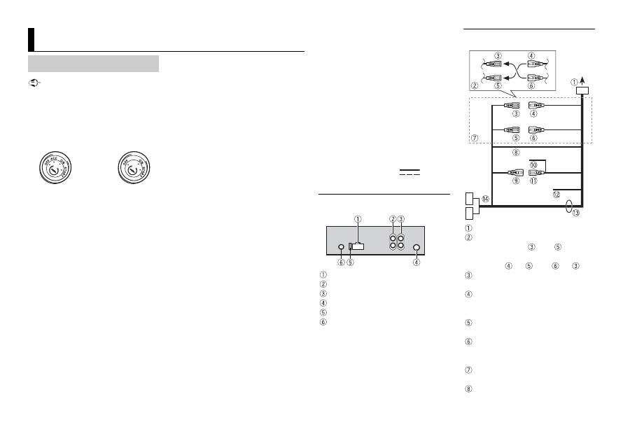
This unit
Power cord input
Rear output or subwoofer output
Front output (Only for MVH-190UI)
Antenna input
Fuse (10 A)
Wired remote input (Only for MVH-
190UI)
Hard-wired remote control adapter
can be connected (sold separately).
Power cord
To power cord input
Depending on the kind of vehicle,
the function of
and
may be
different. In this case, be sure to
connect
to
and
to
.
Yellow
Back-up (or accessory)
Yellow
Connect to the constant 12 V
supply terminal.
Red
Accessory (or back-up)
Red
Connect to terminal controlled by
the ignition switch (12 V DC).
Connect leads of the same colour
to each other.
Black (chassis ground)
15
En
En
g
lis
h
Blue/white
The pin position of the ISO
connector will differ depending on
the type of vehicle. Connect
and
when Pin 5 is an antenna
control type. In another type of
vehicle, never connect
and
.
Blue/white
Connect to the system control
terminal of the power amp (max.
300 mA 12 V DC).
Blue/white
Connect to the auto-antenna relay
control terminal (max. 300 mA 12 V
DC).
Yellow/black (Only for MVH-190UI)
If you use equipment with a Mute
function, wire this lead to the
Audio Mute lead on that
equipment. If not, keep the Audio
Mute lead free of any connections.
Speaker leads
White: Front left
White/black: Front left
Gray: Front right
Gray/black: Front right
Green: Rear left
or subwoofer
Green/black: Rear left
or
subwoofer
Violet: Rear right
or subwoofer
Violet/black: Rear right
or
subwoofer
ISO connector
In some vehicles, the ISO connector
may be divided into two. In this
case, be sure to connect to both
connectors.
NOTES
• Change the initial menu of this unit.
Refer to [SP-P/O MODE] (page 5). The
subwoofer output of this unit is
monaural.
• When using a subwoofer of 2 Ω, be
sure to connect the subwoofer to the
violet and violet/black leads of this
unit. Do not connect anything to the
green and green/black leads.
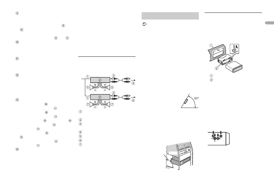
Power amp (sold separately)
Perform these connections when
using the optional amplifier.
System remote control
Connect to blue/white cable.
Power amp (sold separately)
Connect with RCA cables (sold
separately)
To front output*
Front speaker*
To rear output or subwoofer output
Rear speaker or subwoofer
* Only for MVH-190UI
Important
• Check all connections and systems
before final installation.
• Do not use unauthorized parts as
this may cause malfunctions.
• Consult your dealer if installation
requires drilling of holes or other
modifications to the vehicle.
• Do not install this unit where:
– it may interfere with operation of
the vehicle.
– it may cause injury to a passenger
as a result of a sudden stop.
• The semiconductor laser will be
damaged if it overheats. Install this
unit away from hot places such as
near the heater outlet.
• Optimum
performance is
obtained when the
unit is installed at an
angle of less than 60°.
• When installing, to ensure proper
heat dispersal when using this unit,
make sure you leave ample space
behind the rear panel and wrap any
loose cables so they are not blocking
the vents.
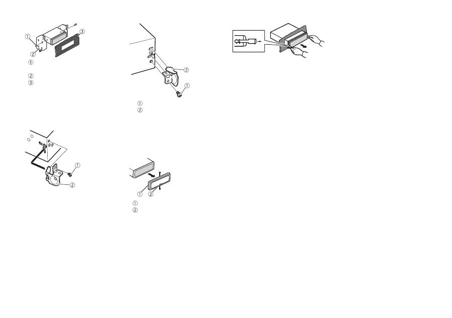
DIN mount installation
1
Insert the supplied mounting
sleeve into the dashboard.
2
Secure the mounting sleeve by
using a screwdriver to bend the
metal tabs (90°) into place.
Dashboard
Mounting sleeve
• Make sure that the unit is
installed securely in place. An
unstable installation may cause
skipping or other malfunctions.
When not using the supplied
mounting sleeve
1
Line up the holes on the
mounting bracket with the holes
on the sides of the unit to attach
the bracket.
2
Screw in one screw on each side to
hold the unit in place.
Installation
Leave ample
space
5 cm
5 cm
16
En
Tapping screw (5 mm × 9 mm,
not supplied with product)
Mounting bracket
Dashboard or console
Using the included bracket
Check to make sure that the included
bracket matches your particular
model of vehicle and then attach it to
the unit as shown below.
Removing the unit (installed
with the supplied mounting
sleeve)
1
Remove the trim ring.
Trim ring
Notched tab
• Releasing the front panel allows
easier access to the trim ring.
• When reattaching the trim ring,
point the side with the notched
tab down.
2
Insert the supplied extraction
keys into both sides of the unit
until they click into place.
3
Pull the unit out of the dashboard.
Screw
Bracket
Оглавление
- Table of Contents
- Getting Started
- Radio
- USB/iPod/AUX
- App Mode
- Using Pioneer ARC APP
- Settings
- Connections/Installation
- Additional Information
- Table des matières
- Mise en route
- Radio
- USB/iPod/AUX
- Mode d’application
- Utilisation de Pioneer ARC APP
- Réglages
- Raccordements/Installation
- Informations complémentaires
- Sommario
- Operazioni preliminari
- Radio
- USB/iPod/AUX
- Modalità app
- Spotify®
- Utilizzare Pioneer ARC APP
- Impostazioni
- Connessioni/Installazione
- Informazioni aggiuntive
- Índice
- Procedimientos iniciales
- Radio
- USB/iPod/AUX
- Modo app
- Spotify®
- Uso de Pioneer ARC APP
- Ajustes
- Conexiones/instalación
- Información complementaria
- Inhaltsverzeichnis
- Erste Schritte
- Radio
- USB/iPod/AUX
- App-Modus
- Spotify®
- Verwenden von Pioneer ARC APP
- Einstellungen
- Anschlüsse/Einbau
- Zusätzliche Informationen
- Inhoud
- Aan de slag
- Radio
- USB/iPod/AUX
- App-modus
- Pioneer ARC APP gebruiken
- Instellingen
- Verbindingen/installatie
- Aanvullende informatie
- Содержание
- Начало работы
- Радио
- USB/iPod/AUX
- Режим приложения
- Spotify®
- Использование Pioneer ARC APP
- Настройки
- Подключения/Установка
- Дополнительная информация


