Pioneer DJM-5000: Operations
Operations: Pioneer DJM-5000
En
11
DRB1492-B
English
Operations
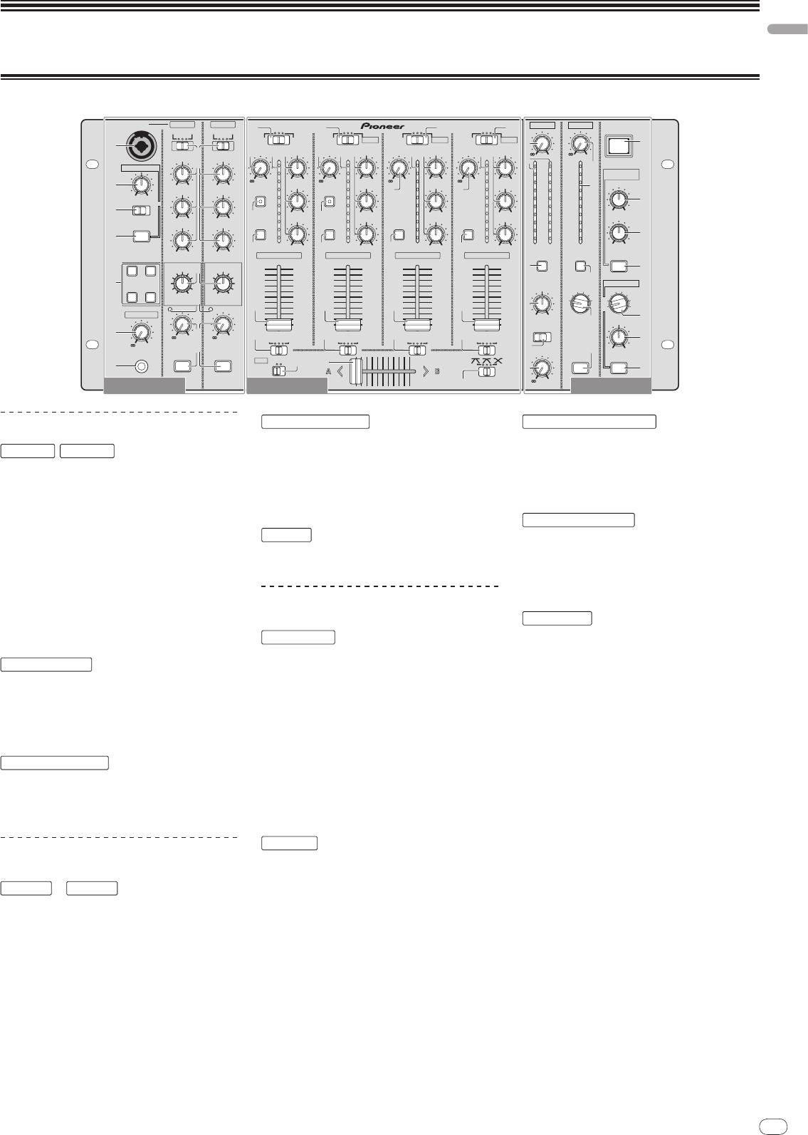
Control Panel
11
MIC 1 MIC 1
MIC 2
MASTER
ZONE
MASTER ZONE
MASTER ZONE
1
DIGITAL1
1
DIGITAL2
LINE
1
LINE
1
LEVEL
LEVEL
BOTH
BOTH
CD
MIC 3
CD
USB 1/2
CD
USB 3/4
CD
USB 5/6
1
1
POWER
i
OUTPUT
2
OUTPUT
2
TRIM
5
HI
2
TRIM
6
HI
TRIM
65
HI
TRIM
5
665
HI
-
0
-
0
HI
HI
TALK OVER
3
14
14
14
14
2
14
14
7
9
9
9
9
9
9
SOUND
-
+9
5
-
26
+6
26
+6
5
-
26
+6
MAXIMIZER
-
+9
5
-
-
+9
-
+9
5
-
26
+6
9
5
5
-
12 +12
-
12 +12
CLARITY
MID
MID
FADER
START
2
MID
FADER
MID
START
2
2
MID
2
MID
8
2
2
2
2
MIN MAX
0
0
0
0
0
0
NORMAL
ADVANCED
c
–2
–2
–2
–2
–2
–2
a
–4
3
-
26
+6
–4
–4
3
-
26
+6
-
26
+6
–4
-
26
+6
–4
–4
MINMAX
-
12 +12
-
12 +12
–7
LOW
–7
LOW
–7
LOW
–7
LOW
DYNAMICS
–7
–7
ON/OFF
LOW
LOW
CUE
–10
CUE
–10
CUE
–10
CUE
–10
–10
–10
b
–15
–15
–15
–15
d
–15
–15
dB
-
26
+6
dB
4
4
-
26
+6
dB
4
-
26
+6
dB
4
-
26
+6
LR
dB
dB
MINMAX
-
12 +12
-
12 +12
CH -1
CH -2
CH -3
CH -4
CUE
CUE
ON/OFF
EFFECT
EFFECT
3
e
4
REVERB
ECHO+VERB
9
5
MIC EFFECT
ZONE ASSIGN
SEND/RETURN
PITCHOCTAVER
BALANCE
34
4
MIC1
LOWHI
LOWHI
2
MASTER
3
MIC2
6
1
MIC
2
MIC1+2
LEVEL
LEVEL
7
7
7
7
4
1
MASTER
HEAD PHONES
L
R
f
LEVEL
a
LEVEL
STEREOMONO
c
-
0
7
-
0
8
ABTHRU
8
ABTHRU
8
ABTHRU
8
ABTHRU
g
-
0
5
8
BOOTH MONITOR
b
MINMAX
PHONES
MIC1 ON
MIC2 ON
MIDI
OFFON
CROSS
ZONE ON
ON/OFF
d
b
9
FADER
6
h
-
0
MC Section DJ Section PA Section
PROFESSIONAL MIXER
a
DJM-
5000
MC Section
MIC 1
,
MIC 2
1 MIC 1 (page 13)
2 OUTPUT (page 13)
3 HI, MID, LOW (page 13)
4 EFFECT (page 13)
5 MIC EFFECT (page 13)
6 Peak Level Indicator (page 13)
7 LEVEL (page 13)
8 MIC1 ON, MIC2 ON (page 13)
TALK OVER
9 Talk-Over Level (page 13)
a NORMAL/
ADVANCED (page 13)
b ON/
OFF (page 13)
HEAD PHONES
c LEVEL (page 12)
d PHONES (page 12)
DJ Section
CH-1
—
CH-4
1 Input Selector Switch (page 12)
2 TRIM (page 12)
3 FADER START (page 12)
4 CUE (page 12)
5 Channel Level Indicator (page 12)
6 HI, MID, LOW (page 12)
7 Channel Fader (page 12)
CROSS FADER
8 Crossfader Assign Switch (page 12)
9 Crossfader (page 12)
a [CROSS FADER] (Crossfader Curve
Selector Switch) (page 12)
MIDI
b MIDI (page 12)
PA Section
MASTER
1 LEVEL (page 12)
2 Master Level Indicator (page 12)
Displays the level of audio signals that have
passed through [LEVEL] in the [MASTER]
channel.
3 CUE (page 12)
4 BALANCE (page 14)
5 MONO/
STEREO (page 14)
6 BOOTH MONITOR (page 14)
ZONE
7 LEVEL (page 14)
8 Zone Level Indicator (page 14)
Displays the level of audio signals that have
passed through [LEVEL] in the [ZONE] channel.
9 CUE (page 12)
a Output Channel Selector Switch (page 14)
b ZONE ON (page 14)
SOUND MAXIMIZER
c CLARITY (page 14)
d DYNAMICS (page 14)
e ON/
OFF (page 14)
SEND/ RETURN
f Output Channel Selector Switch (page 14)
g LEVEL (page 14)
h ON/
OFF (page 14)
POWER
i POWER (page 12)
12
En
DRB1492-B
Operating the DJ section
Outputting sound
1 Press [POWER]
Turn on the power of this unit.
2 Set the input selector switch
Select the input source of each channel from the components connected to this
unit.
! To output sound of the computer connected to the [USB] terminal, switch the
input selector switch for [CH-2], [CH-3], and [CH-4] to [USB].
3 Rotate [TRIM]
Adjusts the level of audio signals input in each channel.
! The channel level indicator lights when the sound is being properly input to
the channel.
4 Set the channel fader to the inner position
Adjusts the level of audio signals output in each channel.
5 Adjust the crossfader assign switch
Switches the output destination of each channel.
— [A]: Assigns to [A] (left) of the crossfader.
— [B]: Assigns to [B] (right) of the crossfader.
— [THRU]: Assigns to the [MASTER] channel (the crossfader is not passed
through).
6 Adjust the crossfader curve switch ([CROSS FADER])
Switches the crossfader curve characteristics.
— [ ]: Makes a sharply increasing curve (if the crossfader is moved away
from the [A] side, audio signals are immediately output from the [B]
side).
— [ ]: Makes a curve shaped between the two curves above and below.
— [
]: Makes a gradually increasing curve (if the crossfader is moved
away from the [A] side, the sound on the [B] side gradually increases,
while the sound on the [A] gradually decreases).
7 Set the crossfader
Outputs audio signals assigned by the crossfader assign switch corresponding to
the curve characteristics selected by [CROSS FADER] (Crossfader Curve Selector
Switch).
! You do not need to follow this step when the crossfader assign switch is set to
[THRU].
8 Rotate [LEVEL] for the [MASTER] channel
The sound is output from [MASTER1] and [MASTER2]. The master level indicator
lights.
Adjusting the sound quality
Rotate [HI], [MID] or [LOW] in each channel
Refer to Specifications on page 17 for the range of sound that can be adjusted by
each control.
Monitoring sound with headphones
1 Connect headphones to the [PHONES] jack
2 Press [CUE] for the channel to be monitored
The button lights up brightly in orange.
3 Turn the [LEVEL] dial for [HEAD PHONES]
Sound is output from the headphones in the channel selected by [CUE].
! Sound output from the headphones varies according to the combination of
channels selected by [CUE]. See the table below.
12
CH-1
‒
Headphone Output
CH-4
MASTER ZONE
L channel
R channel
ON
OFF
OFF
CH (L)
CH (R)
OFF
ON
OFF
MASTER (L)
MASTER (R)
OFF
OFF
ON
ZONE (L)
ZONE (R)
ON
ON
OFF
CH (MONO)
MASTER (MONO)
ON
OFF
ON
CH (MONO)
ZONE (MONO)
OFF
ON
ON
MASTER (L)+ZONE (L)
MASTER (R)+ZONE (R)
MASTER (MONO)
ON
ON
ON
CH (MONO)
+ZONE (MONO)
Using the fader to play a Pioneer DJ player
(fader start)
If you connect a Pioneer DJ player using a control cable (supplied with a DJ
player), you can start playback of control other operations of the DJ player with
the fader of this unit.
The fader start feature is available only when a Pioneer DJ player is connected to
[CH-1] or [CH-2].
Connect a Pioneer DJ player to this unit in advance (page 6).
Start playback using the channel fader
1 Set the crossfader assign switch to [THRU]
2 Press [FADER START]
Turn on the fader start function. The button lights up brightly in orange.
3 Set the channel fader to the outermost position
4 Set the cue on the DJ player
The DJ player pauses playback at the cue point.
5 Set the channel fader to the inner position
Playback starts on the DJ player.
! If you set the channel fader back to the original position, the player instanta-
neously returns to the cue point already set and pauses playback (back cue).
Start playback using the crossfader
1 Set the crossfader assign switch to [A] or [B]
2 Press [FADER START]
Turn on the fader start function. The button lights up brightly in orange.
3 Set the crossfader
Set to the farmost end in the opposite direction to the channel to be fader started.
4 Set the cue on the DJ player
The DJ player pauses playback at the cue point.
5 Set the crossfader
Playback starts on the DJ player.
! If you set the crossfader back to the original position, the player instanta-
neously returns to the cue point already set and pauses playback (back cue).
Operating the DJ software
The DJM-5000 also outputs the operating data for the buttons and dials in MIDI
format. If you connect a computer with a built-in MIDI-compatible DJ software
via a USB cable, you can operate the DJ software on this unit.
Install the DJ software on your computer in advance. Also, adjust audio and MIDI
settings for the DJ software.
1 Connect the USB port on this unit to your computer
For details about connections, see Connecting a computer on page 7.
2 Start the DJ software
3 Set [MIDI] to [ON]
Transmission of the MIDI messages begin.
! You can send MIDI messages altogether according to the position of buttons,
faders, or control knobs (snapshot).
! Adjust faders and control knobs to transmit messages based on the corre-
sponding position. For details about the messages generated by this unit, see
List of MIDI Messages on page 10.
4 Set [MIDI] to [OFF]
The MIDI messages are not transmitted even if you operate this unit.
! Monitoring is canceled if you press [CUE] again. The button lights up dimly in
orange.
English
En
13
DRB1492-B
Using the talk-over feature
Operating the MC section
1 Rotate the talk-over level
Set the attenuation level of sound besides the one in the microphone channel.
Using a microphone
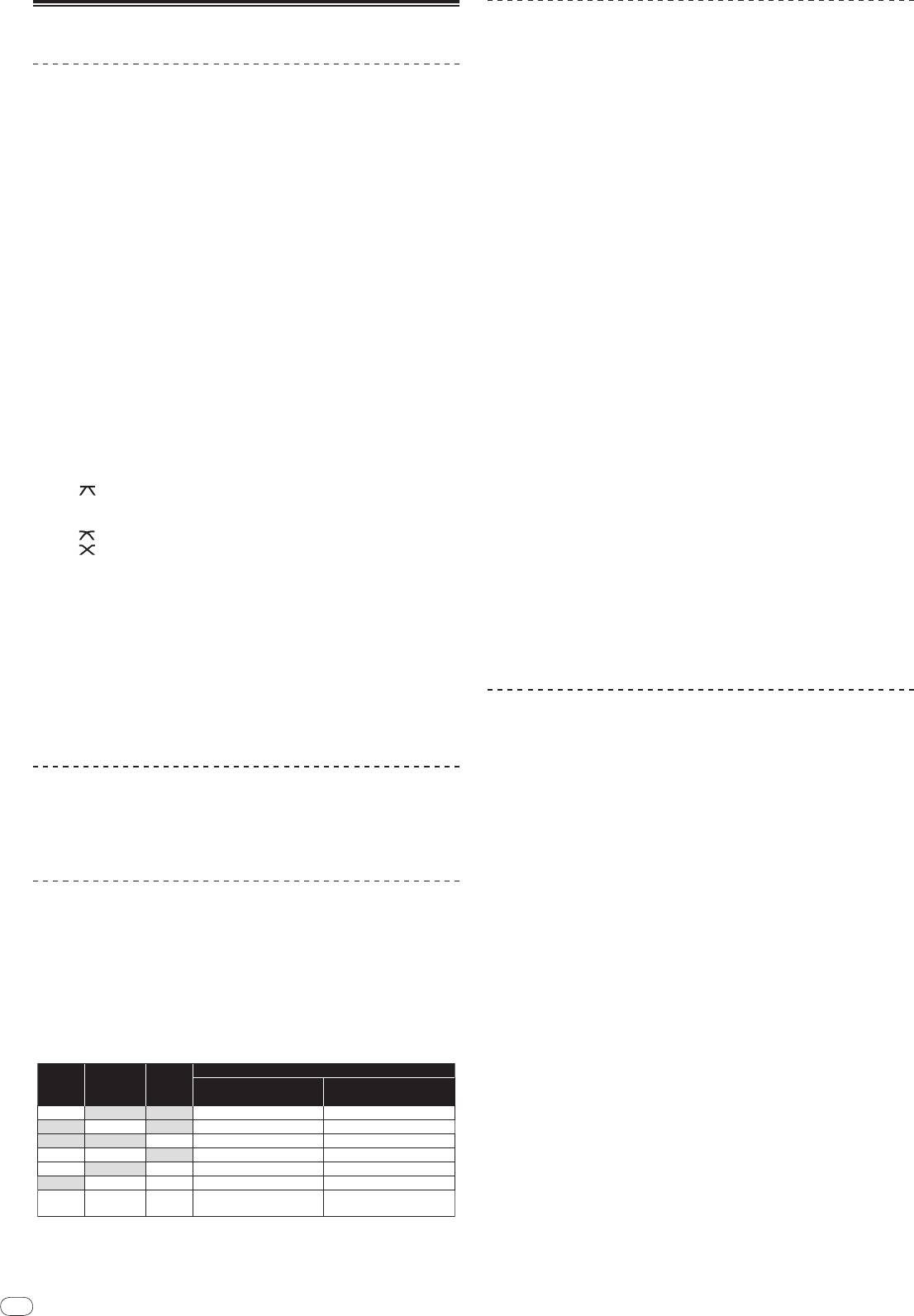
2 Switch between [NORMAL]/
[ADVANCED]
The attenuation mode for the talk-over function switches.
1 Switch [OUTPUT]
! Normal talk over:
Select the output destination of the sound output from the [MIC1] or [MIC2]
The sound output from channels other than the microphone channel is
channel.
attenuated by the amount set for the talk over level.
2 Rotate [LEVEL] for the microphone channel
Adjusts the level of audio signals output from the microphone channel.
! Pay attention that rotating to the extreme right position outputs a very loud
sound.
3 Press [MIC1 ON] for the [MIC1] channel or [MIC2 ON] for the
[MIC2] channel
Turn on the microphone channel. The button lights up in green.
4 Input audio signals to the microphone
Sound is output to the output destination selected in step 1.
! The peak level indicator lights in different colors corresponding to the level of
audio being input.
— Green: Permissible level
— Orange: Appropriate level
— Red: Excessive level (lower the level of audio by rotating [LEVEL] to the
left)
Adjusting the sound quality
Rotate [HI], [MID] or [LOW] for the [MIC1] or [MIC2] channel
Refer to Specifications on page 17 for the range of sound that can be adjusted by
each control.
Using the microphone effect feature
1 Press [MIC EFFECT (REVERB, ECHO+VERB, OCTAVER or PITCH)]
Turn on the microphone effect function. The button flashes in blue.
! The effect varies depending on the button.
2 Rotate [EFFECT]
Adds an effect to the sound output from the microphone channel.
! The effect varies according to the rotation direction and position of [EFFECT].
Effect Name Descriptions
1
REVERB
Adds a reverberation effect to the original sound.
1
ECHO+VERB
Adds reverberation and echo effects to the original sound.
1
OCTAVER
Adds sound with 1 octave up and down to the original sound.
Changes the musical interval within the range of 1 octave up and
PITCH
down. Rotate it to the right and left to change the interval 1 octave up
and down respectively.
1 The more you rotate it to the right, the louder the effect sound.
! When you turn off the microphone effect function, press the flashing
[MIC EFFECT (REVERB, ECHO+VERB, OCTAVER, PITCH)] once again. The but-
ton lights up in blue.
13
dB
NORMAL
ADVANCED
Frequency
! Advanced talk over:
Only the voice band of the sound output from channels other than the
microphone channel is attenuated by the amount set for the talk over
level.
dB
NORMAL
ADVANCED
Frequency
3 Press [ON/
OFF] for [TALK OVER]
Turn on the talk-over function. The button lights up in red.
! When audio signals are input in the microphone channel, the sound, besides
the one in the microphone channel, is attenuated according to the attenua-
tion mode setting and the position of the control.
14
En
DRB1492-B
Operating the PA section
Outputting sound from the ZONE terminal
You can output sound from the [ZONE] terminal besides the sound output from
the master channel.
1 Set the output channel selector switch for the [ZONE] channel
Select the channel output from the [ZONE] terminal.
! Sound output varies according to the position of the switch.
Switch
1 2 3 4 MASTER MIC
Position
Audio
1
1
1
1
Microphone
Microphone
CH-1
CH-2
CH-3
CH-4
2
3
Output
Channel
Channel
1 Audio is output regardless of the position of faders and control knobs.
2 Audio is output regardless of the position of [LEVEL] for the [MASTER] channel.
3 Audio is output only from the microphone channel, for which [OUTPUT] is set to [BOTH]
or [ZONE].
2 Press [ZONE ON] for the [ZONE] channel
Turn on the [ZONE] channel. The button lights up in green.
3 Rotate [LEVEL] for the [ZONE] channel
Sound is output at the [ZONE] terminal. The zone level indicator lights up.
! To turn the [ZONE] channel off, press [ZONE ON] again. The button turns off.
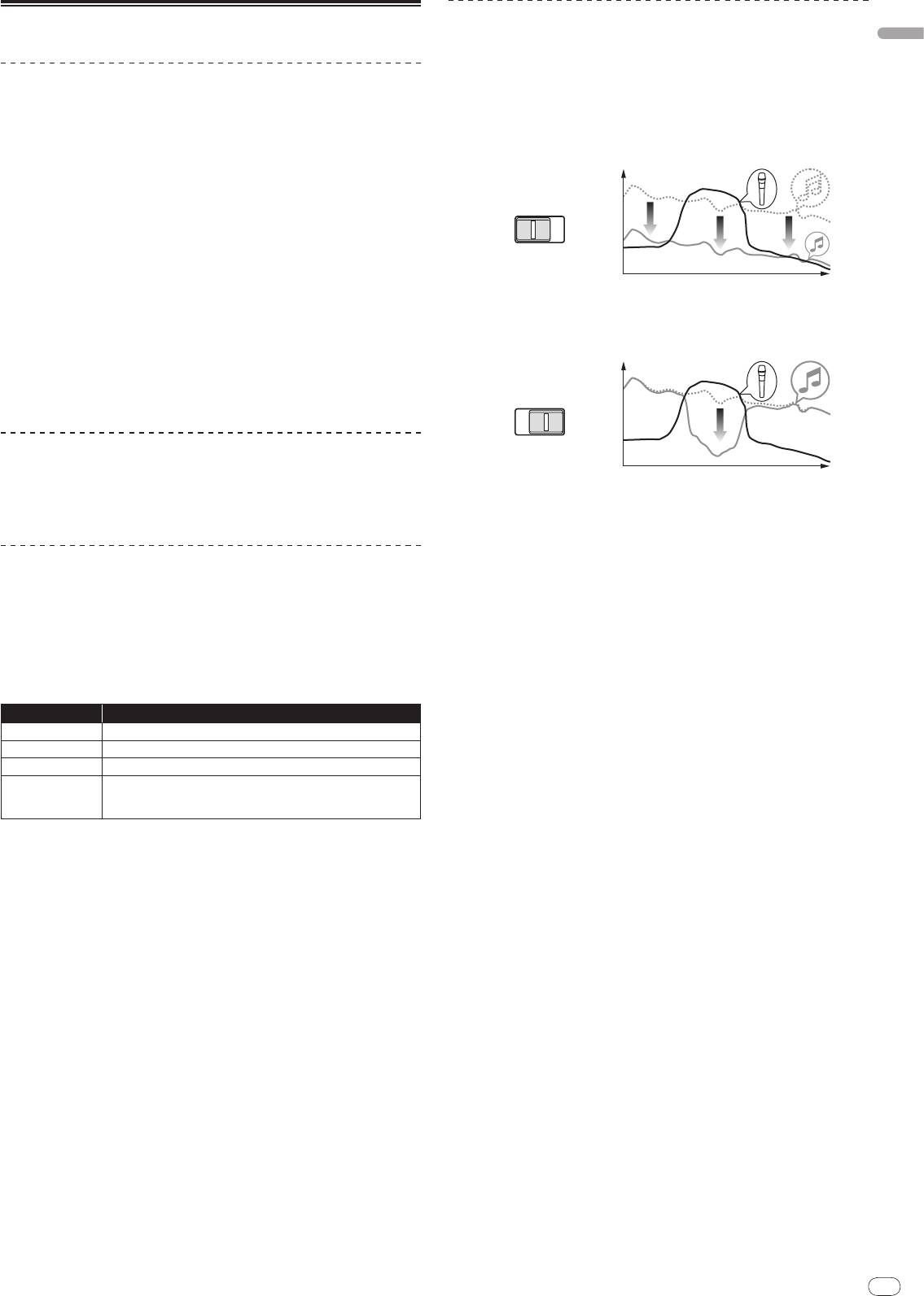
Using the sound maximizer feature
1 Press [ON/
OFF] for [SOUND MAXIMIZER]
Turn on the sound maximizer function. The button lights up in blue.
2 Rotate [CLARITY] or [DYNAMICS]
The effect of the sound maximizer varies according to the rotation direction and
position of the control.
! The output audio level increases according to the sound maximizer effect
when the dial is turned clockwise. Pay attention to the output audio level
when using the sound maximizer function.
14
dB
Frequency
DYNAMICS
CLARITY
MINMAX
MINMAX
! To stop the sound output at the [SEND] terminal, press the flashing [ON/
OFF].
The button lights up.
Switching between monaural and stereo audio
You can switch between monaural and stereo audio for the sound output at the
[MASTER1], [MASTER2], [BOOTH], [REC OUT] or [PHONES] terminal.
Switch between [MONO]/
[STEREO]
! [MONO]: Outputs monaural audio.
! [STEREO]: Outputs stereo audio.
Adjusting the L/
R balance of audio
The left/
right balance of the sound output from the [MASTER1], [MASTER2],
[BOOTH], [REC OUT] and [PHONES] terminals can be adjusted.
1 Set [MONO]/
[STEREO] to [STEREO]
2 Rotate [BALANCE]
The L/
R balance of audio varies according to the rotation direction and position
of the [BALANCE] control.
! Rotating to the rightmost position outputs only the right sound of stereo
audio. Rotating to the leftmost position outputs only the left sound of stereo
audio.
Audio is output from the [BOOTH] terminal
The master channel audio, except the microphone channel audio, is output from
the [BOOTH] terminal regardless of the position of [LEVEL] in the [MASTER]
channel.
Rotate [BOOTH MONITOR]
Adjusts the level of audio signals output at the [BOOTH] terminal.
! The range of sound that can be adjusted varies according to the control.
— CLARITY: Adjusts the attack and outline of sound mainly in the mid and
high range (high hat, snare, etc.).
— DYNAMICS: Adjusts modulation and rhythm mainly in the low range.
! When you turn off the sound maximizer function, press [ON/
OFF] again. The
light of the button turns off.
Using the external effector
1 Connect the external effector
[ON/
OFF] of [SEND/
RETURN] lights up in red. When the external effector is not
connected, [ON/
OFF] does not light up.
! For details about connections, see Connections on page 5.
2 Set the output channel selector switch for the [SEND/
RETURN]
channel
Select the channel output from the [SEND] terminal.
! Sound output varies according to the position of the switch.
Switch
1 2 3 4 MIC 1 MIC 2 MIC1+2 MASTER
Position
Audio
1
CH-1 CH-2 CH-3 CH-4 MIC 1 MIC 2
MIC1+2
Master Channel
Output
1 The microphone sound output from the master channel is output from the [SEND] chan-
nel.
3 Press [ON/
OFF] for [SEND/
RETURN]
Sound is output at the [SEND] terminal. The button flashes in red.
4 Turn the [LEVEL] dial for [SEND/
RETURN]
Adjusts the level of audio signals input at the [RETURN] terminal.
Оглавление
- Contents
- Before start
- Connections
- Operations
- Additional information
- Sommaire
- Informations
- Raccordements
- Opérations
- Informations supplémentaires
- Inhalt
- Vor der
- Anschlüsse
- Bedienungen
- Zusätzliche Informationen
- Indice
- Prima di cominciare
- Collegamenti
- Operazioni
- Informazioni aggiuntive
- Inhoud
- Alvorens te
- Aansluitingen
- Bediening
- Aanvullende informatie
- Contenido
- Antes de empezar a
- Conexiones
- Operaciones
- Información adicional
- Содержание
- До начала
- Подключения
- Операции
- Дополнительная информация


