Pioneer DJM-5000: Connections
Connections: Pioneer DJM-5000
En
5
DRB1492-B
English
Connections
Be sure to turn off the power and unplug the power cord from the power outlet whenever making or changing connections.
Refer to the operating instructions for the component to be connected.
Connect the power cord after all the connections between devices have been completed.
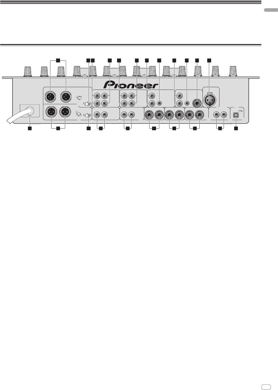
Rear Panel
5
1
3 3 4 4
4 4 5 5
6 72
DJM-
5000
MIC 2
R
L
ZONE
LINE
CD
LINE
CD CD
CD
L
CH-4
L
CH-3 CH-2 CH-1
L
L
3 COLD
1 GND
CONTROL
CONTROL
MIC 3
2 HOT
-
12dB
-
6dB
0dB
ZONE AT T.
RR
R
R
MASTER1
R
L
MASTER2
R
L
REC OUT
R
BOOTH
(TRS)
L
R
SEND
L
(
MONO
)
R
RETURN
L
(
MONO
)
DIGITAL IN USB
1 GND
21
-
12dB
-
6dB
0dB
R
L
3 COLD
2 HOT
MASTER AT T.
16 141517 13 12 11 10
9 8
1 ZONE (page 6)
a RETURN (page 6)
An output terminal for the ZONE channel.
Connect to the output terminal of an external effector. When the [L] channel
only is connected, the [L] channel input is simultaneously input to the [R]
2 ZONE ATT
channel.
Use to switch the attenuation level of audio signals output at the [ZONE]
terminal. Select from 0 dB, -6 dB and -12 dB.
b SEND (page 6)
Connect to the input terminal of an external effector. When the [L] channel
3 LINE (page 6)
only is connected, a monaural audio signal is output.
Connect to a cassette deck or a line level output component.
c BOOTH (page 6)
4 CD (page 6)
Output terminals for a booth monitor, compatible with balanced or unbal-
Connect to a DJ player or a line level output component.
anced output for a TRS connector.
5 CONTROL (page 6)
d REC OUT (page 6)
This is a control terminal for a DJ player. Use the fader of this unit to control
This is an output terminal for recording.
a DJ player.
e MASTER2 (page 6)
6 MIC3 (page 6)
Connect to a power amplifier, etc.
Connect to a microphone.
f MASTER ATT
7 MIC2 (page 6)
Use to switch the attenuation level of audio signals output at the [MASTER1]
Connect to a microphone.
or [MASTER2] terminal. Select from 0 dB, -6 dB and -12 dB.
8 USB (page 7)
g MASTER1 (page 6)
Connect to a computer.
Connect to a power amplifier, etc.
9 DIGITAL IN (page 6)
h Power cable
Connect to a digital audio output component.
Connect to an AC outlet. Plug in the power cord after all connections have
been made.
6
En
DRB1492-B
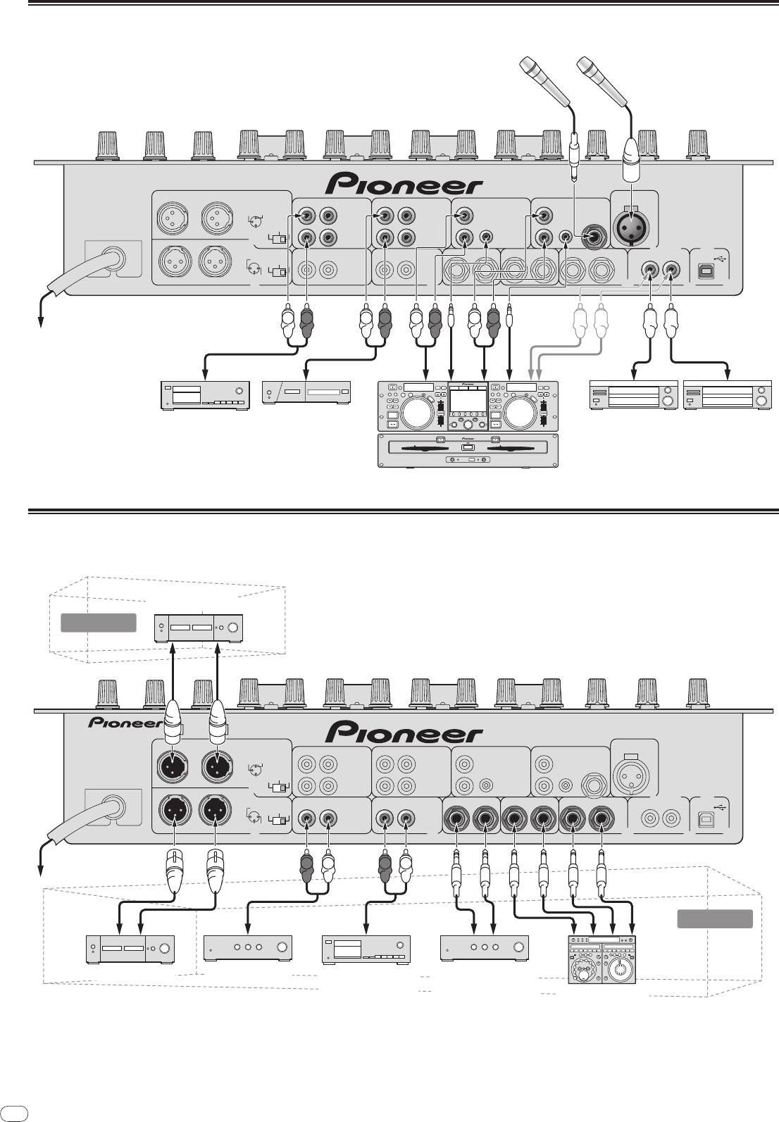
Connecting input terminals
6
Microphone
DJM-
5000
MIC 2
R
L
ZONE
LINE
CD
LINE
CD CD
CD
L
CH-4
L
CH-3 CH-2 CH-1
L
L
3 COLD
1 GND
CONTROL
CONTROL
MIC 3
2 HOT
-
12dB
-
6dB
0dB
ZONE AT T.
RR
R
R
MASTER1
)
R
L
MASTER2
BOOTH
(
(
)
DIGITAL IN USB
1 GND
R
L
REC OUT
R
(TRS)
L
R
SEND
L
MONO
R
RETURN
L
MONO
21
-
12dB
-
6dB
0dB
R
L
3 COLD
2 HOT
MASTER AT T.
To an AC outlet
L
L
RR
L
L
RR
Cassette deck, CD player, etc.
Digital audio output device
(a line level output device)
Pioneer DJ player
1
1 Connect a control cable to use the fader start feature (page 12).
Connecting output terminals
2 A sound is output separately from the one in the master channel (MASTER/
ZONE split-out).
2
Power amplifier
Subroom
DJM-
5000
MIC 2
R
L
ZONE
LINE
CD
LINE
CD CD
CD
L
CH-4
L
CH-3 CH-2 CH-1
L
L
3 COLD
1 GND
CONTROL
CONTROL
MIC 3
2 HOT
-
12dB
-
6dB
0dB
ZONE AT T.
RR
R
R
MASTER1
R
L
MASTER2
R
L
REC OUT
R
BOOTH
(TRS)
L
R
SEND
L
(
MONO
)
R
RETURN
L
(
MONO
)
DIGITAL IN USB
1 GND
21
-
12dB
-
6dB
0dB
R
L
3 COLD
2 HOT
MASTER AT T.
To an AC outlet
R LR L
Main room
Power amplifierPower amplifier
Cassette deck, etc.
Power amplifier
(an analog input
(for a booth monitor)
External effector
recording device)
English
En
7
DRB1492-B
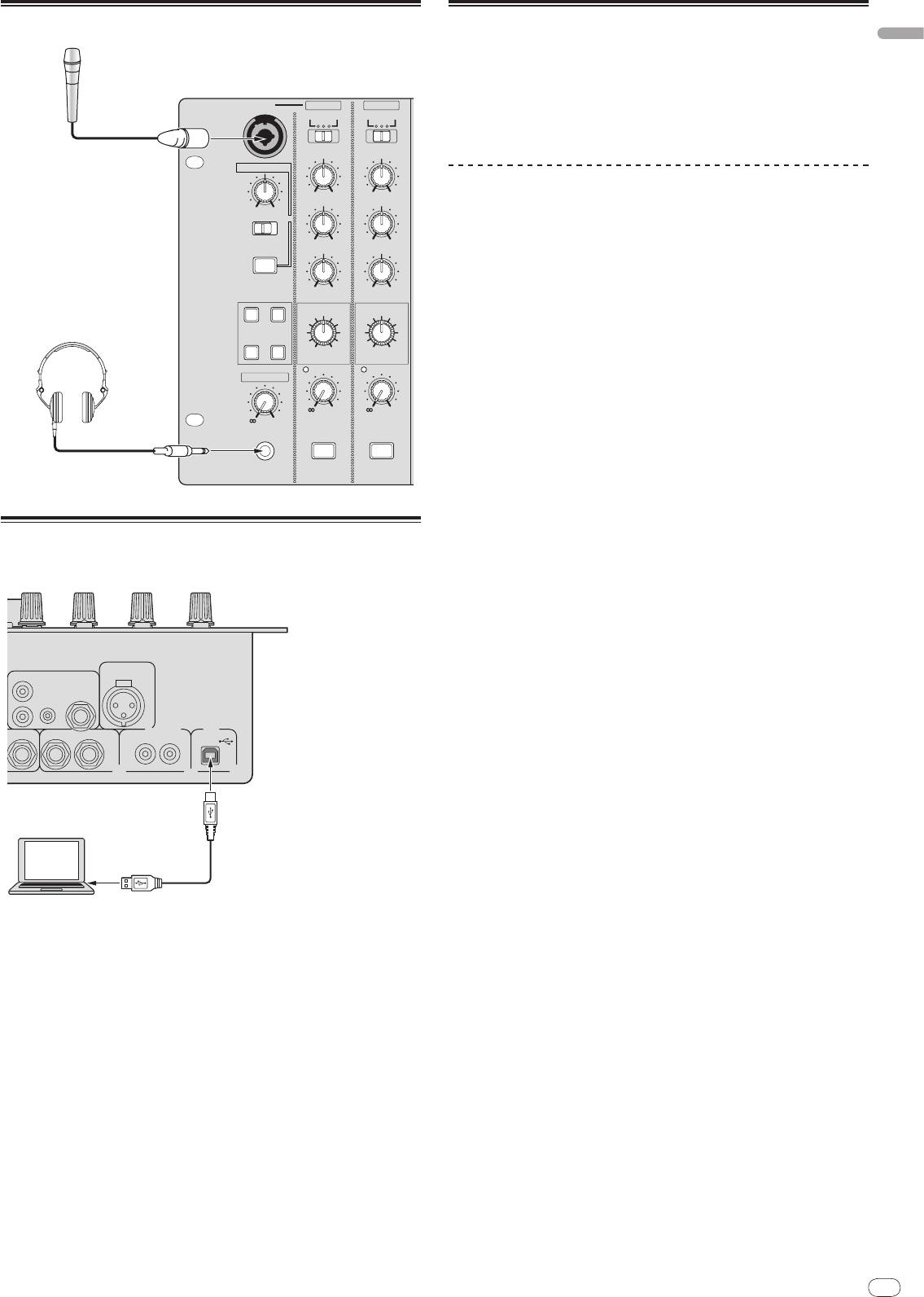
Connecting to the control panel
7
Microphone
MIC 1 MIC 1
MIC 2
MASTER ZONE
MASTER ZONE
BOTH
BOTH
OUTPUT
OUTPUT
HI
HI
TALK OVER
-
12 +12
-
12 +12
MID
MID
MINMAX
NORMAL
ADVANCED
-
12 +12
-
12 +12
ON/OFF
LOW
LOW
-
12 +12
-
12 +12
EFFECT
EFFECT
REVERB
ECHO+VERB
Headphones
MIC EFFECT
PITCHOCTAVER
LOWHI
LOWHI
LEVEL
LEVEL
HEAD PHONES
LEVEL
-
0
-
0
-
0
PHONES
MIC1 ON
MIC2 ON
Connecting a computer
CD
L
CH-1
CONTROL
R
N
DJM-
5000
MIC 2
MIC 3
D
L
(
MONO
)
R
RETURN
(
)
DIGITAL IN USB
L
MONO
21
Computer
About the USB audio driver software
The driver software is an audio driver exclusively used to output audio signals
from a computer. If you would like to connect this unit to a Windows- or Mac-
installed computer, we recommend you install the driver software in your com-
puter first.
! You can find the latest information on the driver software on our website
(shown below).
http://www.prodjnet.com/support/
Software Use Agreement
This software usage agreement (hereafter referred to as “the agreement”) deter-
mines matters related to use of the DJ function software (hereafter referred to
as “the software”) between the customer and Pioneer Corporation (hereafter
referred to as “Pioneer”).
Be sure to read the following articles carefully before installing and using the
software. Use of the software implies that the customer has consented to the
agreement. If you do not consent to the agreement, do not install or use the
software.
[Usage agreement]
On the condition of complying with the contents of this agreement, the customer
has permission to install and use this software on a single personal computer.
[Restrictions]
The customer shall not create, distribute or send reproductions of this software
over networks or from one computer to another. In addition, the customer shall
not modify, sell, lend, transfer or resell the software, nor distribute, create, etc.,
secondary works of the software. Furthermore, the customer shall not reverse
compile, reverse engineer, reverse assemble or otherwise change the software
into formats perceptible by humans.
[Copyrights, etc.]
Copyrights and all other intellectual property rights related to this software are
the property of Pioneer and its affiliates. This software is protected by copyright
laws and the provisions of international treaties.
[Repudiation of guarantee and technical support]
This software and all associated documentation, etc., is provided on an “as is”
basis. Pioneer does not guarantee the customer nor third parties regarding
merchantability, compatibility with specific purposes, violation of rights of oth-
ers or any other matters, nor does it guarantee technical support related to this
software or associated documentation. Note that repudiation of guarantee may
not be not recognized in some countries and regions by mandatory provisions, in
which case this repudiation of guarantee may not apply. The customer’s rights
may differ in some countries and regions.
[Limitation of liability]
Pioneer and other suppliers of this software shall accept no responsibility
whatsoever for damages incurred through use of or inability to use this software
or any associated documentation (including but not limited to loss of profits,
business interruptions, damages resulting from loss or impairment of informa-
tion, etc.), even if Pioneer has been notified of the possibility of such damages.
Limitation of liability related to incidental or direct damages may not be recog-
nized in some countries and regions by mandatory provisions, in which case this
limitation of liability may not apply. Note that, regardless of the case, the respon-
sibility of Pioneer and its subsidiaries regarding this software shall not exceed
the sum paid by the customer to Pioneer or its subsidiaries. This repudiation of
limitation of liability is a fundamental element of the arrangement between the
customer and Pioneer.
Connect with the supplied USB cable.
[Governing law]
This agreement complies with the laws and ordinances of Japan and shall be
interpreted accordingly. This agreement stipulates all articles of the arrangement
between the customer and Pioneer, and shall be applied with priority over any
prior and existing agreements related to this matter (regardless of whether oral
or in writing). The Tokyo District Court shall be the court of exclusive jurisdiction
in first instance for any disputes arising regarding this agreement.

8
En
DRB1492-B
Installation Procedure (Macintosh)
Cautions on Installation
Carefully read “Cautions on Installation” before installing the driver software.
! Before installing the driver software, be sure to turn off the power of this unit
! To install or uninstall the driver software, you need to be authorized by the
and disconnect the USB cable from both this unit and your computer.
administrator of your computer. Have the name and password of the adminis-
! If you connect this unit to your computer without installing the driver soft-
trator of your computer ready in advance.
ware first, an error may occur on your computer depending on the system
environment.
1 Insert the supplied CD-ROM into the CD drive of your
! If you have discontinued the installation process in progress, step through
computer
the installation process again from the beginning according to the following
The CD-ROM folder appears.
procedure.
! Double-click the CD icon on the desktop when folders are not displayed after
! Carefully read the provisions of the Software Use Agreement before installing
a CD-ROM has been loaded.
the driver software for exclusive use with this unit.
! Before installing the driver software, terminate all other programs running on
2 Double-click [DJM-5000_M_X.X.X.dmg]
your computer.
The [DJM-5000AudioDriver] menu screen appears.
! The driver software is compatible with the following OSs.
— Mac OS X (10.3.9 and later)
3 Double-click [DJM-5000AudioDriver.pkg]
®
— Windows Vista
Home Basic/
HomePremium/
Ultimate/
Business
The driver installation screen appears.
®
— Windows
XP Home Edition/
Professional (SP2 or later)
®
4 Check the details on the screen and click [Continue Anyway]
The driver software is not compatible with 64-bit OS (Windows
XP
®
Professional x64 edition and Windows Vista
64-bit).
5 When the Software Use Agreement screen appears, select
! The CD-ROM with the driver software includes an installer running in the fol-
[English], carefully read the Software Use Agreement and click
lowing 12 languages.
[Continue Anyway]
English, French, German, Italian, Dutch, Spanish, Portuguese, Russian,
You can select one from multiple languages depending on the system environ-
Simplified Chinese, Traditional Chinese, Korean, and Japanese
ment of your computer.
If the language of your OS is one other than the ones listed above, select
[English] following the instructions on the screen.
6 If you consent to the provisions of the Software End User
License Agreement, click [Agree]
If you do not consent to the provisions of the Software Use Agreement, click [I
Installing the driver software
disagree] and stop installation.
7 Proceed with installation according to the instructions on the
Installation Procedure (Windows)
screen
! To stop installation in progress, click [Cancel].
Carefully read “Cautions on Installation” before installing the driver software.
! When the installation of the driver software is completed, you need to reboot
! To install or uninstall the driver software, you need to be authorized by the
your computer.
administrator of your computer. Log in as the administrator of your computer
before proceeding with the installation.
1 Insert the supplied CD-ROM into the CD drive of your
Connecting the DJM-5000 and computer
computer
The CD-ROM folder appears.
1 Connect this unit to your computer via a USB cable
! If the CD-ROM folder is not displayed after a CD-ROM is loaded, open the CD
This unit functions as an audio device conforming to the ASIO standards.
drive from [Computer (or My Computer)] in the [START] menu.
! When using applications supporting ASIO, [USB 1/
2], [USB 3/
4] and
[USB 5/
6] can be used as inputs.
2 Double-click [DJM-5000_X.XXX.exe]
! When using applications supporting DirectX, only [USB 5/
6] can be used as
The driver installation screen appears.
the input.
3 When the language selection screen appears, select [English]
! The computer’s recommended operating environment depends on the DJ
application. Be sure to check the recommended operating environment for
and click [OK]
the DJ application you are using.
You can select one from multiple languages depending on the system environ-
ment of your computer.
2 Press [POWER]
Turn on the power of this unit.
4 Carefully read the Software Use Agreement and if you consent to
! The message [Installing device driver software] may appear when the DJM-
the provisions, put a check mark in [I agree.] and click [OK]
5000 is connected to the computer for the first time or when it is reconnected
If you do not consent to the provisions of the Software Use Agreement, click
to the computer’s USB port. Wait until the [Your devices are ready for use]
[Cancel] and stop installation.
message appears.
! When installing on Windows XP
5 Proceed with installation according to the instructions on the
— [Can Windows connect to Windows Update to search for software?]
screen
may appear while the installation is in progress. Select [No, not this
If [Windows Security] appears on the screen while the installation is in progress,
time] and click [Next] to continue with the installation.
click [Install this driver software anyway] and continue with the installation.
— [What do you want the wizard to do?] may appear while the instal-
! When installing on Windows XP
lation is in progress. Select [Install the software automatically
If [Hardware Installation] appears on the screen while the installation is in
(Recommended)] and click [Next] to continue with the installation.
progress, click [Continue Anyway] and continue with the installation.
— If [Windows Security] appears on the screen while the installation is in
! When the installation program is completed, a completion message appears.
progress, click [Install this driver software anyway] and continue with
! When the installation of the driver software is completed, you need to reboot
the installation.
your computer.
8

English
En
9
DRB1492-B
Adjusting the buffer size (Windows)
About USB-MIDI channel setting
Use this procedure to adjust the computer’s buffer size when using an ASIO
Turn off the power of this unit in advance.
audio driver.
1 Set [MIDI] to [ON]
Click Windows [START] menu >[View All
Programs]>[Pioneer]>[DJM-5000]>[DJM-5000 ASIO Settings
2 Press and hold [FADER START] for [CH-1] and [CH-2]
Utility]
simultaneously and press [POWER]
A sufficiently large buffer size decreases the chance of sound dropout (sound
When the MASTER [CUE] and ZONE [CUE] buttons light orange, the MIDI channel
interruption) but increases audio signal transmission delay (latency).
setting mode is set. Press and hold in [FADER START] for [CH-1] and [CH-2] until
! When an application program (DJ software, etc.) with this unit set as a fixed
the buttons light orange.
device is running, terminate the program before adjusting the buffer size.
! The current MIDI channel setting is displayed in the master level indicator.
[L] shows the position of 10, while [R] the position of 1.
! The MIDI channel is initially set to [1].
Checking the version of the driver software
Example: to show 16
Procedure for checking (Windows)
Click Windows [START] menu >[View All
Programs]>[Pioneer]>[DJM-5000]>[DJM-5000 Version Display
Utility]
The [Version] screen appears.
Procedure for checking (Macintosh)
Click [Apple]>[About This Mac]>[More Info]>[Extensions]>[DJM-
5000 USBAudio]
The [Version] screen appears.
Checking the latest information on the driver
software
For the latest information on the driver software for exclusive use with this unit,
visit our website shown below.
http://www.prodjnet.com/support/
9
14
9
5
2
0
–2
–4
–7
–10
–15
dB
LR
3 Press [CUE] in the [MASTER] channel
The MIDI channel changes by one channel each time you press it.
Select a MIDI channel to change the setting.
4 Press and hold [CUE] for the [ZONE] channel
Save the changes made for the MIDI channel.
While settings are being saved, [ON/
OFF] flashes for the [SOUND MAXIMIZER]
channel. Lights up when the saving is completed.
! Do not turn off the power while saving MIDI channel settings.
5 Press [POWER]
Turn off the power of this unit.
6 Press [POWER]
Turn on the power of this unit again.
Start in the normal mode. The MIDI channel setting is changed.
10
En
DRB1492-B
MIDI
List of MIDI Messages
SW
Category SW Name
Messages
Notes
Type
MSB
MIDI
SEND/
RETURN
SW
Category SW Name
Messages
SW Bn 30 dd 127
Notes
CH-1
Type
MSB
SEND/
RETURN
SW Bn 31 dd 127
HI
VR Bn 2 dd 0-127
CH-2
MID
VR Bn 3 dd 0-127
SEND/
RETURN
SW Bn 32 dd 127
CH-3
LOW
VR Bn 4 dd 0-127
SEND/
RETURN
FADER START
BTN Bn 58 dd OFF=0, ON=127
SW Bn 33 dd 127
CH-1
CH-4
CUE
BTN Bn 46 dd OFF=0, ON=127
SEND/
SEND/
RETURN
SW Bn 34 dd 127
Channel fader VR Bn 11 dd 0-127
RETURN
MIC 1
Crossfader
SEND/
RETURN
SW Bn 41 dd A=0, THRU=64, B=127
SW Bn 35 dd 127
Assign Switch
MIC 2
HI
VR Bn 7 dd 0-127
SEND/
RETURN
SW Bn 36 dd 127
MIC 1+2
MID
VR Bn 8 dd 0-127
SEND/
RETURN
LOW
VR Bn 9 dd 0-127
SW Bn 37 dd 127
MASTER
FADER START
BTN Bn 59 dd OFF=0, ON=127
CH-2
LEVEL
VR Bn 66 dd 0-127
CUE
BTN Bn 47 dd OFF=0, ON=127
ON/
OFF VR Bn 40 dd OFF=0, ON=127
Channel fader VR Bn 12 dd 0-127
LEVEL
VR Bn 67 dd 0-127
Crossfader
SW Bn 42 dd A=0, THRU=64, B=127
NORMAL/
NORMAL=0,
Assign Switch
TALK OVER
SW Bn 68 dd
ADVANCED
ADVANCED=127
HI
VR Bn OE dd 0-127
ON/
OFF BTN Bn 69 dd OFF=0, ON=127
MID
VR Bn OF dd 0-127
REVERB
BTN Bn 6A dd OFF=0, ON=127
LOW
VR Bn 15 dd 0-127
ECHO+VERB
BTN Bn 6B dd OFF=0, ON=127
CH-3
CUE
BTN Bn 48 dd OFF=0, ON=127
MIC EFFECT
OCTAVER
BTN Bn 6C dd OFF=0, ON=127
Channel fader VR Bn 13 dd 0-127
PITCH
BTN Bn 6D dd OFF=0, ON=127
Crossfader
SW Bn 43 dd A=0, THRU=64, B=127
HEAD
Assign Switch
LEVEL
VR Bn 1A dd 0-127
PHONES
HI
VR Bn 51 dd 0-127
HI
VR Bn 1E dd 0-127
MID
VR Bn 5C dd 0-127
MID
VR Bn 6E dd 0-127
LOW
VR Bn 52 dd 0-127
MIC 1
LOW
VR Bn 1F dd 0-127
CH-4
CUE
BTN Bn 49 dd OFF=0, ON=127
EFFECT
VR Bn 70 dd 0-127
Channel fader VR Bn 14 dd 0-127
MIC1 ON
BTN Bn 71 dd OFF=0, ON=127
Crossfader
SW Bn 44 dd A=0, THRU=64, B=127
HI
VR Bn 72 dd 0-127
Assign Switch
MID
VR Bn 73 dd 0-127
Crossfader VR Bn 0B dd 0-127
CROSS FADER
MIC 2
LOW
VR Bn 74 dd 0-127
Left=0, Middle=64,
CROSS FADER
SW Bn 5F dd
Right=127
EFFECT
VR Bn 75 dd 0-127
LEVEL
VR Bn 18 dd 0-127
MIC2 ON
BTN Bn 76 dd OFF=0, ON=127
CUE
BTN Bn 4A dd OFF=0, ON=127
! MIDI ON/
OFF controls whether to transmit MIDI messages.
! “n” in the MIDI message “Bn” is a value of the MIDI channel set by the user, ranging
MASTER
BALANCE
VR Bn 17 dd 0-127
from 0x00 to 0x0F (1 to 16 on the setting screen)
MONO/
STEREO SW Bn 60 dd MONO=0, STEREO=127
BOOTH MONITOR
VR Bn 19 dd 0-127
LEVEL
VR Bn 61 dd 0-127
CUE
BTN Bn 62 dd OFF=0, ON=127
ZONE ASSIGN
SW Bn 20 dd 127
CH-1
ZONE ASSIGN
SW Bn 21 dd 127
CH-2
ZONE ASSIGN
ZONE
SW Bn 22 dd 127
CH-3
ZONE ASSIGN
SW Bn 23 dd 127
CH-4
ZONE ASSIGN
SW Bn 24 dd 127
MASTER
ZONE ASSIGN OFF
SW Bn 25 dd 127
ON/
OFF BTN Bn 63 dd OFF=0, ON=127
CLARITY
VR Bn 64 dd 0-127
SOUND
DYNAMICS
VR Bn 65 dd 0-127
MAXIMIZER
ON/
OFF BTN Bn 4E dd OFF=0, ON=127
10
Оглавление
- Contents
- Before start
- Connections
- Operations
- Additional information
- Sommaire
- Informations
- Raccordements
- Opérations
- Informations supplémentaires
- Inhalt
- Vor der
- Anschlüsse
- Bedienungen
- Zusätzliche Informationen
- Indice
- Prima di cominciare
- Collegamenti
- Operazioni
- Informazioni aggiuntive
- Inhoud
- Alvorens te
- Aansluitingen
- Bediening
- Aanvullende informatie
- Contenido
- Antes de empezar a
- Conexiones
- Operaciones
- Información adicional
- Содержание
- До начала
- Подключения
- Операции
- Дополнительная информация


