Pioneer VSX-820-S Silver: Connecting your equipment
Connecting your equipment: Pioneer VSX-820-S Silver
Connecting your equipment03
Chapter 3:
Connecting your equipment
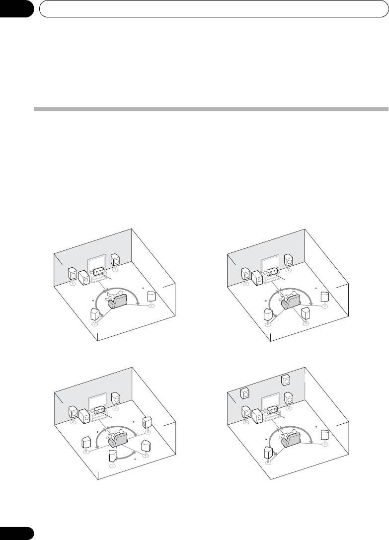
Placing the speakers
By connecting the left and right front speakers (L/R), the center speaker (C), the left and right
surround speakers (SL/SR), and the subwoofer (SW), a 5.1 ch surround system can be enjoyed.
Further, by using an external amplifier, you can connect the left and right surround back speakers
(
SBL
/
SBR
) and the left and right front height speaker (
FHL
/
FHR
) to boost your system up to a 7.1 ch
surround system.
• You can also connect one surround back speaker (SB) and enjoy a 6.1 ch surround system.
To achieve the best possible surround sound, install your speakers as shown below.
R
R
L
L
C
C
SW
120
SW
120
120
120
SR
SR
SB
SL
SL
FHR
R
FHL
R
L
L
C
C
SR
90
SW
SW
120
90
120
SBR
SR
SL
60
SBL
SL
a. This layout is available only when the additional amplifier is connected to the unit and the surround back
or front height speakers are connected to the amplifier. For details, see Connect the surround back or front height
speakers on page 19.
16
En
5.1 channel surround system:
6.1 channel surround
a
(Surround back) system:
7.1 channel surround
7.1 channel surround
a
a
(Surround back) system:
(Front height) system:
VSX-820_SYXCN_En.book 16 ページ 2010年4月12日 月曜日 午後6時52分
Connecting your equipment 03
17
En
English
Deutsch
Français
Italiano
Nederlands
Español
VSX-820_SYXCN_En.book 17 ページ 2010年4月12日 月曜日 午後6時52分
Hints on the speaker placement
• If the surround speakers cannot be set
directly to the side of the listening position
Where you put your speakers in the room has a
with a 7.1-channel system, the surround
big effect on the quality of the sound. The
effect can be enhanced by turning off the
following guidelines should help you to get the
Up Mix function (see Setting the Up Mix
best sound from your system.
function on page 38).
• The subwoofer can be placed on the floor.
• Try not to place the surround speakers
Ideally, the other speakers should be at
farther away from the listening position
about ear-level when you’re listening to
than the front and center speakers. Doing
them. Putting the speakers on the floor
so can weaken the surround sound effect.
(except the subwoofer), or mounting them
very high on a wall is not recommended.
• Place the left and right front height
speakers at least one meter directly above
• For the best stereo effect, place the front
the left and right front speakers.
speakers 2 m to 3 m apart, at equal
distance from the TV.
• If you’re going to place speakers around
CAUTION
your CRT TV, use shielded speakers or
• Make sure that all speakers are securely
place the speakers at a sufficient distance
installed. This not only improves sound
from your CRT TV.
quality, but also reduces the risk of
• If you’re using a center speaker, place the
damage or injury resulting from speakers
front speakers at a wider angle. If not, place
being knocked over or falling in the event
them at a narrower angle.
of external shocks such as earthquakes.
• Place the center speaker above or below
the TV so that the sound of the center
Important
channel is localized at the TV screen. Also,
make sure the center speaker does not
• To connect the surround back or front
cross the line formed by the leading edge
height speakers, an additional amplifier is
of the front left and right speakers.
required. Connect the additional amplifier
to the PRE OUT SURR BACK/FRONT
• It is best to angle the speakers towards the
HEIGHT outputs of this unit and connect
listening position. The angle depends on
the surround back or front height speakers
the size of the room. Use less of an angle
to the additional amplifier (see Connect
for bigger rooms.
the surround back or front height speakers
• Surround and surround back speakers
on page 19).
should be positioned 60 cm to 90 cm
The Pre Out setting must be set if the above
higher than your ears and titled slight
connections are performed. Select
downward. Make sure the speakers don’t
SURR.BACK if the surround back speaker
face each other. For DVD-Audio, the
is connected and HEIGHT if the front
speakers should be more directly behind
height speaker is connected (If neither the
the listener than for home theater
surround back speaker nor the front height
playback.
speaker is connected, either setting will
suffice) (see The Pre Out Setting on
page 47).
Connecting your equipment03
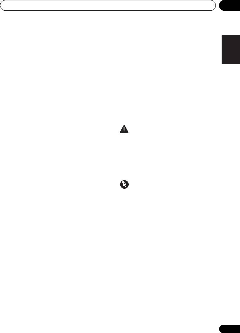
Connecting the speakers
The receiver will work with just two stereo
You can use the speakers connected to the B
speakers (the front speakers in the diagram)
speaker terminals to listen to stereo playback
but using at least three speakers is
in another room. See Switching the speaker
recommended, and a complete setup is best
system on page 20 for the listening options
for surround sound.
with this setup.
Make sure you connect the speaker on the
You can use speakers with a normal
right to the right (R) terminal and the speaker
impedance between 6 Ω and 16 Ω.
on the left to the left (L) terminal. Also make
However, note that only the front speakers are
sure the positive and negative (+/–) terminals
set to a value between 12 Ω and 16 Ω if you
on the receiver match those on the speakers.
select SPAB in Switching the speaker system
on page 20.
Be sure to complete all connections before
connecting this unit to the AC power source.
18
En
SUBWOOFER
SPEAKERS
A
PRE OUT
FRONT
RL
CD-R/TAPE
DVR/VCR
SURR BACK /
ADAPTER PORT
AC IN
FRONT
(
OUTPUT 5 V 100 mA MAX
)
HEIGHT
L
(
Single
)
VIDEO
OUT
DVR/VCR
TV/SAT
OUT IN
IN
R
PRE OUT
CD
CD-R/TAPE
DVR/VCR
L
SPEAKERS
B
E
IN
IN
MONITOR OUT
DVD IN BD IN
ANTENNA
P
R
P
B
Y
MONITOR
R
FM
OUT
110-127 V 220-240 V
UNBAL
RL
TV/SAT
DVD BD
75
L
IN
2
VOLTAGE SELECTOR
(
DVD
)
IN
IN
AM
R
LOOP
IN
1
(
BD
)
E
ASSIGNABLE
AUDIO
COMPONENT VIDEO
1
2
C
L
RSLSR
RL
SURROUND
CENTER
LR
SW
Center speaker
Front speakers
Surround speakers
Speaker system B
Powered subwoofer
VSX-820_SYXCN_En.book 18 ページ 2010年4月12日 月曜日 午後6時52分
Connecting your equipment 03
19
En
English
Deutsch
Français
Italiano
Nederlands
Español
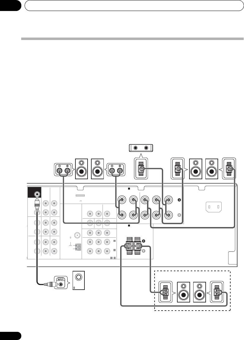
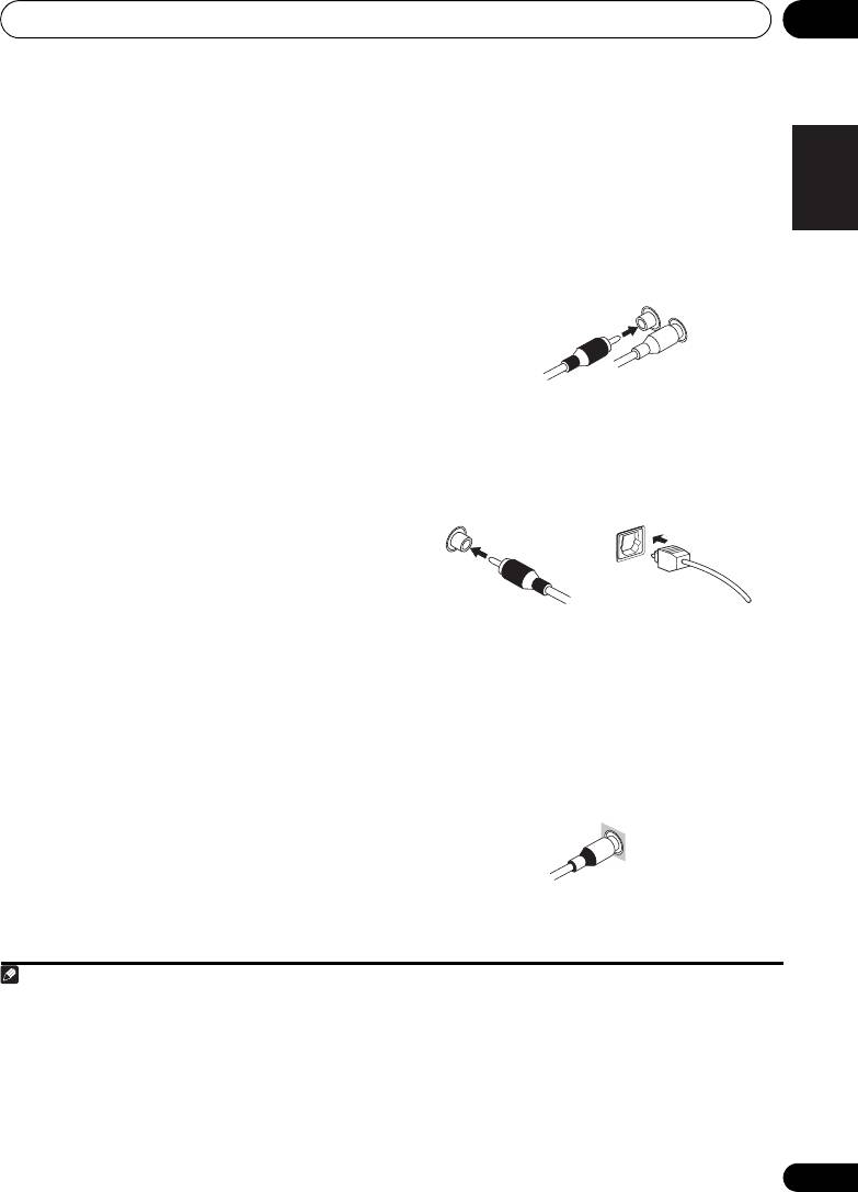
Bare wire connections
Connect the surround back or front
A-Speaker terminals:
height speakers
1 Twist exposed wire strands together.
Connect the PRE OUT outputs of the unit and
additional amplifier to add a surround back or
2 Loosen terminal and insert exposed wire.
front height speaker.
3 Tighten terminal.
• If the surround back speaker or the front
height speaker is connected, set the Pre
Out setting (see The Pre Out Setting on
123
page 47).
B-Speaker terminals:
1 Twist exposed wire strands together.
2 Push open the tabs and insert exposed
wire.
3 Release the tabs.
CAUTION
• These speaker terminals carry
HAZARDOUS LIVE voltage. To prevent
the risk of electric shock when connecting
or disconnecting the speaker cables,
disconnect the power cord before touching
any uninsulated parts.
• Make sure that all the bare speaker wire is
• You can use the additional amplifier on the
twisted together and inserted fully into the
surround back channel pre-outs for a
speaker terminal. If any of the bare speaker
single speaker as well. In this case plug the
wire touches the back panel it may cause
amplifier into the left (L (Single)) terminal
the power to cut off as a safety measure.
only.
10 mm
12 3
10 mm
IN BD
SUBWOOFER
PRE OUT
CD-R/TAPE
DVR/VCR
SURR BACK /
ADAPTER
FRONT
(
OUTPUT 5 V 1
DVD
HEIGHT
L
(
Single
)
OUT
R
TV/SAT
PRE OUT
CD
CD-R/TAPE
DVR/VCR
L
COAXIAL
ASSIGNABLE
IN
IN
M
DVR/VCR
IN
1
ANTENNA
R
(
CD
)
FM
UNBAL
OPTICAL
TV/SAT
DVD BD
75
IN
2
L
OUT
IN
IN
AM
IN
1
(
CD-R/TAPE
)
R
LOOP
ASSIGNABLE
HDMI
1 2
AUDIO
SBL/FHL SBR/FHR
ANALOG
INPUT
LR
Surround back or
front height speakers
Surround back or
front height
channel amplifier
VSX-820_SYXCN_En.book 19 ページ 2010年4月12日 月曜日 午後6時52分
Connecting your equipment03
Switching the speaker system
Three speaker system settings are possible
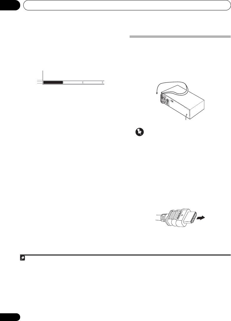
Making cable connections
using the SPEAKERS button.
Make sure not to bend the cables over the top
• Use the SPEAKERS button on the front
of this unit (as shown in the illustration). If this
1
panel to select a speaker system setting.
happens, the magnetic field produced by the
transformers in this unit may cause a
humming noise from the speakers.
Press repeatedly to choose a speaker system
option:
• SPA – Sound is output from the speakers
connected to the A speaker terminals and
PRE OUT SURR BACK/FRONT HEIGHT
(multichannel playback is possible).
• SPB – Sound is output from the two
Important
speakers connected to speaker system B
• Before making or changing connections,
(only stereo playback is possible).
switch off the power and disconnect the
• SPAB – Sound is output from speaker
power cord from the AC outlet.
system A, the two speakers in speaker
• Before unplugging the power cord, switch
system B, and the subwoofer.
the power into standby.
Multichannel sources are downmixed only
when the STEREO or ALC mode is selected
HDMI cables
for stereo output from speaker systems A
Both video and sound signals can be transmitted
2
and B.
simultaneously with one cable.
If connecting the
• SP – No sound is output from the
player and the TV via this receiver, for both
speakers.
3
connections, use HDMI cables.
Be careful to connect the terminal in the
proper direction.
20
En
Note
1 The subwoofer output depends on the settings you made in Speaker Setting on page 43. However, if SPB is selected above,
no sound is heard from the subwoofer (the LFE channel is not downmixed).
2 You can use speakers with a normal impedance between 6 Ω and 16 Ω. However, be aware that only the front speakers are set
to a value between 12 Ω and 16 Ω when you select SPAB.
SPEAKERS DIMMER DISPLAY
3 • Set the HDMI parameter in Setting the Audio options on page 38 to THRU (THROUGH) and set the input signal in Choosing
the input signal on page 41 to HDMI, if you want to hear HDMI audio output from your TV (no sound will be heard from this
receiver).
• If the video signal does not appear on your TV, try adjusting the resolution settings on your component or display. Note that
some components (such as video game units) have resolutions that may not be displayed. In this case, use a (analog)
composite connection.
• When the video signal from the HDMI is 480i, 480p, 576i or 576p, Multi Ch PCM sound and HD sound cannot be received.
HDMI cable
VSX-820_SYXCN_En.book 20 ページ 2010年4月12日 月曜日 午後6時52分
Connecting your equipment 03
21
En
English
Deutsch
Français
Italiano
Nederlands
Español
About HDMI
Analog audio cables
The HDMI connection transfers
Use stereo RCA phono cables to connect
uncompressed digital video, as well as almost
analog audio components. These cables are
every kind of digital audio that the connected
typically red and white, and you should
component is compatible with, including DVD-
connect the red plugs to R (right) terminals
Video, DVD-Audio, SACD, Dolby Digital Plus,
and white plugs to L (left) terminals.
Dolby TrueHD, DTS-HD Master Audio (see
below for limitations), Video CD/Super VCD
and CD.
This receiver incorporates High-Definition
®
Multimedia Interface (HDMI
) technology.
This receiver supports the functions described
1
below through HDMI connections.
Digital audio cables
• Digital transfer of uncompressed video
Commercially available coaxial digital audio
(contents protected by HDCP (1080p/24,
cables or optical cables should be used to
1080p/60, etc.))
4
connect digital components to this receiver.
2
• 3D signal transfer
2
• Deep Color signal transfer
2
• x.v.Color signal transfer
• Input of multi-channel linear PCM digital
audio signals (192 kHz or less) for up to 8
channels
3
Video cables
•
Input of the following digital audio formats:
– Dolby Digital, Dolby Digital Plus, DTS,
Standard RCA video cables
High bitrate audio (Dolby TrueHD, DTS-HD
These cables are the most common type of
Master Audio), DVD-Audio, CD, SACD
video connection and are used to connect to
(DSD signal), Video CD, Super VCD
the composite video terminals. The yellow
HDMI, the HDMI Logo and High-Definition
plugs distinguish them from cables for audio.
Multimedia Interface are trademarks or
registered trademarks of HDMI Licensing, LLC in
the United States and other countries.
“x.v.Color” and x.v.Color logo are trademarks of
Sony Corporation.
Note
®
®
1 • Use a High Speed HDMI
cable. If HDMI cable other than a High Speed HDMI
cable is used, it may not work properly.
• When an HDMI cable with a built-in equalizer is connected, it may not operate properly.
2 Signal transfer is only possible when connected to a compatible component.
3 • HDMI format digital audio transmissions require a longer time to be recognized. Due to this, interruption in the audio may
occur when switching between audio formats or beginning playback.
• Turning on/off the device connected to this unit's HDMI OUT terminal during playback, or disconnecting/connecting the
HDMI cable during playback, may cause noise or interrupted audio.
4 • When connecting optical cables, be careful when inserting the plug not to damage the shutter protecting the optical socket.
• When storing optical cable, coil loosely. The cable may be damaged if bent around sharp corners.
• You can also use a standard RCA video cable for coaxial digital connections.
Analog audio cables
Right (red)
Left (white)
Coaxial digital audio cable Optical cable
Standard RCA video cable
VSX-820_SYXCN_En.book 21 ページ 2010年4月12日 月曜日 午後6時52分
Connecting your equipment03
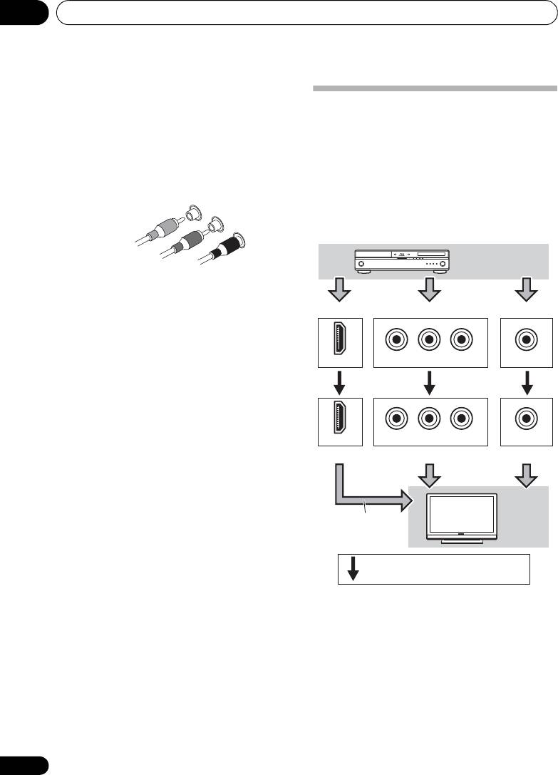
Component video cables
Use component video cables to get the best
About video outputs connection
possible color reproduction of your video
This receiver is not loaded with a video
source. The color signal of the TV is divided into
converter. When you use component video
the luminance (Y) signal and the color (P
B and
cables or HDMI cables for connecting to the
P
R) signals and then output. In this way,
input device, the same cables should be used
interference between the signals is avoided.
for connecting to the TV.
The signals input from the analog (composite
and component) video inputs of this unit will
not be output from the HDMI OUT.
22
En
Component video cables
Green (Y)
Blue (P
B)
Red (P
R)
P
R
P
B
Y
HDMI IN
COMPONENT VIDEO IN
VIDEO IN
P
R
P
B
Y
HDMI OUT
COMPONENT VIDEO MONITOR OUT
MONITOR OUT
Playback
component
Terminal for connection with source device
Terminal for connection with TV monitor
The OSD will not
appear.
TV
Video signals can be output.
VSX-820_SYXCN_En.book 22 ページ 2010年4月12日 月曜日 午後6時52分
Connecting your equipment 03
23
En
English
Deutsch
Français
Italiano
Nederlands
Español
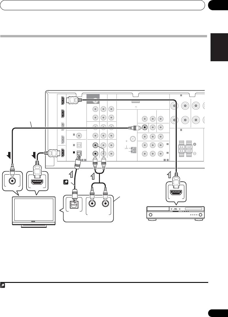
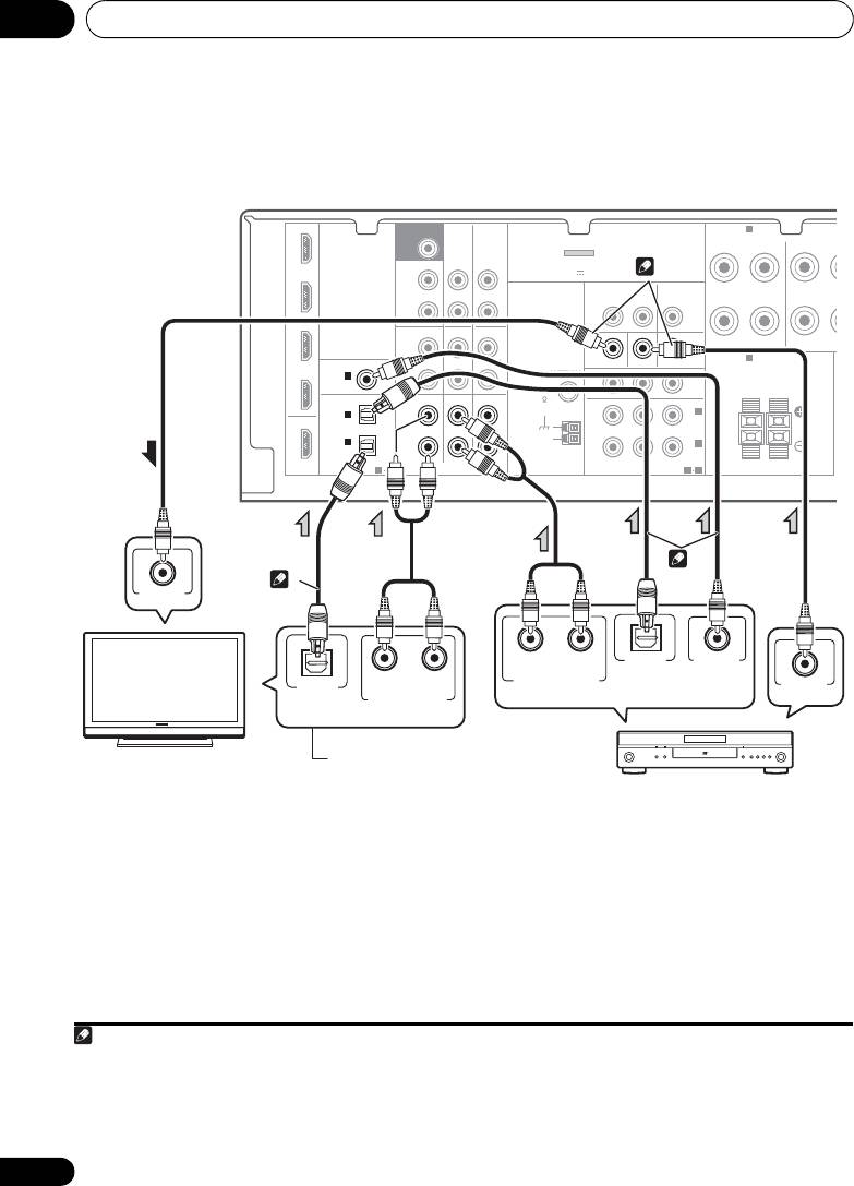
Connecting a TV and playback components
Connecting using HDMI
If you have an HDMI or DVI (with HDCP) equipped component (Blu-ray disc player, etc.), you can
connect it to this receiver using a commercially available HDMI cable.
• If the receiver is connected to a TV using an HDMI cable, the OSD will not be displayed. Be
12
sure to use a standard RCA analog video cable to connect.
Note
IN BD
SUBWOOFER
SPEAKERS
A
PRE OUT
FRONT
RL
SURROU
CD-R/TAPE
DVR/VCR
SURR BACK /
ADAPTER PORT
FRONT
(
OUTPUT 5 V 100 mA MAX
)
DVD
HEIGHT
L
(
VIDEO
Single
)
OUT
DVR/VCR
TV/SAT
OUT IN
IN
R
TV/SAT
PRE OUT
CD
CD-R/TAPE
DVR/VCR
L
SPEAKERS
B
COAXIAL
ASSIGNABLE
IN
IN
MONITOR OUT
DVD IN BD IN
DVR/VCR
IN
1
ANTENNA
P
R
P
B
Y
MONITOR
R
(
CD
)
FM
OUT
UNBAL
RL
OPTICAL
TV/SAT
DVD BD
75
IN
2
L
IN
2
OUT
(
DVD
)
IN
IN
AM
IN
1
(
R
LOOP
IN
1
CD-R/TAPE
)
(
BD
)
ASSIGNABLE
ASSIGNABLE
HDMI
1 2
AUDIO
COMPONENT VIDEO
1
2
1 If you wish to see the OSD screen (for setup, etc.), switch the TV input to analog. (With HDMI input, the OSD will not be
displayed.)
2 If the connection was made using an optical cable, you’ll need to tell the receiver which digital input you connected the TV to
(see Choosing the input signal on page 41).
N
R
MONITOR
OUT
VIDEO IN
HDMI IN
HDMI OUT
RL
OPTICAL
DIGITAL AUDIO OUT
ANALOG AUDIO OUT
This connection is
necessary in order to
see the OSD of the
unit on the TV.
This connection is
2
required in order to
listen to the sound of
the TV over the receiver.
Select one
HDMI/DVI-compatible
Blu-ray disc player
HDMI/DVI-compatible TV
VSX-820_SYXCN_En.book 23 ページ 2010年4月12日 月曜日 午後6時52分
Connecting your equipment03
Connecting your component with no HDMI terminal
This diagram shows connections of a TV and DVD player (or other playback component) with no
123
HDMI terminal to the receiver.
24
En
Note
IN BD
SUBWOOFER
SPEAKERS
A
PRE OUT
FRONT
SURROU
RL
CD-R/TAPE
DVR/VCR
SURR BACK /
ADAPTER PORT
FRONT
(
OUTPUT 5 V 100 mA MAX
)
DVD
HEIGHT
L
(
VIDEO
Single
)
OUT
DVR/VCR
TV/SAT
OUT IN
IN
R
TV/SAT
PRE OUT
CD
CD-R/TAPE
DVR/VCR
L
SPEAKERS
B
COAXIAL
ASSIGNABLE
IN
IN
MONITOR OUT
DVD IN BD IN
DVR/VCR
IN
1
ANTENNA
P
R
P
B
Y
R
MONITOR
MONITOR
(
CD
)
FM
OUT
OUT
UNBAL
RL
OPTICAL
TV/SAT
DVD BD
75
IN
2
L
IN
2
OUT
(
DVD
)
IN
IN
AM
IN
1
LOOP
IN
1
(
CD-R/TAPE
)
R
BD
(
)
ASSIGNABLE
ASSIGNABLE
HDMI
1 2
AUDIO
COMPONENT VIDEO
1
2
1 If the connection was made using an optical cable, you’ll need to tell the receiver which digital input you connected the TV to
(see Choosing the input signal on page 41).
2 If the connection was made using an optical or a coaxial cable, you’ll need to tell the receiver which digital input you connected
the DVD player to (see Choosing the input signal on page 41).
3 If both TV and player has a component video jacks, you can connect these too. See Using the component video jacks on page 26
for more on this.
N
R
VIDEO IN
RL
OPTICAL
COAXIAL
DIGITAL AUDIO OUT
RL
ANALOG AUDIO OUT
OPTICAL
VIDEO OUT
DIGITAL AUDIO OUT
ANALOG AUDIO OUT
3
2
1
Select one
Select one
This connection is
TV
required in order to
listen to the sound of
the TV over the receiver.
DVD player
VSX-820_SYXCN_En.book 24 ページ 2010年4月12日 月曜日 午後6時52分
Connecting your equipment 03
25
En
English
Deutsch
Français
Italiano
Nederlands
Español
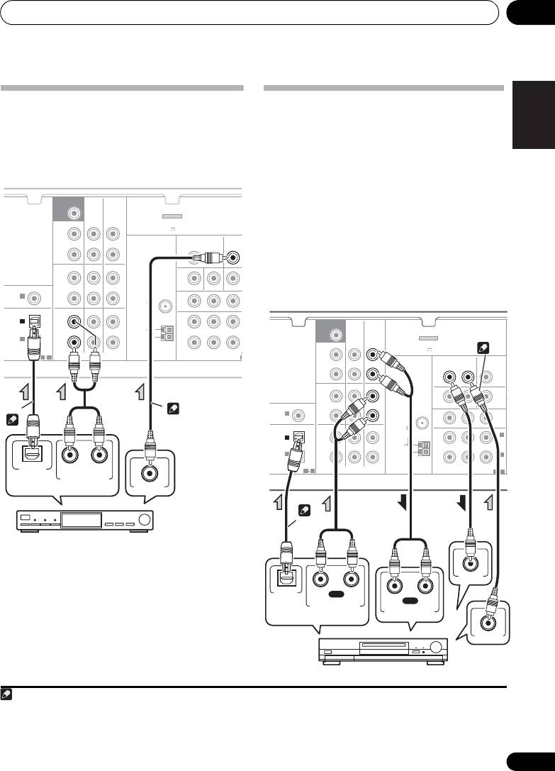
Connecting a satellite receiver
Connecting an HDD/DVD
or other digital set-top box
recorder, VCR and other video
Satellite and cable receivers, and terrestrial
sources
digital TV tuners are all examples of so-called
This receiver has audio/video inputs and
12
‘set-top boxes’.
outputs suitable for connecting analog or
digital video recorders, including HDD/DVD
recorders and VCRs.
• Only the signals that are input to the
VIDEO IN terminal can be output from the
VIDEO OUT terminal.
• Audio signals that are input through the
digital terminal will not be output from the
analog terminal.
Note
CD-R/TAPE
DVR/VCR
SURR BACK /
ADAPTER PORT
FRONT
(
OUTPUT 5 V 100 mA MAX
)
HEIGHT
L
(
)
VIDEO
Single
OUT
DVR/VCR
TV/SAT
OUT IN
IN
R
PRE OUT
CD
CD-R/TAPE
DVR/VCR
L
COAXIAL
ASSIGNABLE
IN
IN
MONITOR OUT
DVD IN BD IN
IN
1
P
R
P
B
Y
M
R
(
CD
)
OPTICAL
TV/SAT
DVD BD
L
IN
IN
IN
1
(
R
CD-R/TAPE
)
ASSIGNABLE
ASSIGN
1 2
AUDIO
COMPONENT VIDEO
1 If the connection was made using an optical cable, you’ll need to tell the receiver which digital input you connected the set-
top box or video component to (see Choosing the input signal on page 41).
2 If the set-top box or video component also has an HDMI or a component video output, you can connect this too. See Connecting
using HDMI on page 23 or Using the component video jacks on page 26 for more on this.
A
SUBWOOFER
PRE OUT
ANTENNA
FM
UNBAL
75
IN
2
AM
LOOP
OPTICAL
RL
DIGITAL AUDIO OUT
ANALOG AUDIO OUT
VIDEO OUT
2
1
Select one
STB
SUBWOOFER
PRE OUT
CD-R/TAPE
DVR/VCR
SURR BACK /
ADAPTER PORT
FRONT
(
OUTPUT 5 V 100 mA MAX
)
HEIGHT
L
(
)
VIDEO
Single
OUT
DVR/VCR
TV/SAT
OUT IN
IN
R
PRE OUT
CD
CD-R/TAPE
DVR/VCR
L
COAXIAL
ASSIGNABLE
IN
IN
MONITOR OUT
DVD IN BD IN
IN
1
ANTENNA
P
R
P
B
Y
R
MONITOR
MONITOR
(
CD
)
FM
OUT
OUT
UNBAL
OPTICAL
TV/SAT
DVD BD
75
IN
2
L
IN
2
(
DVD
)
IN
IN
AM
IN
1
LOOP
IN
1
(
CD-R/TAPE
)
R
(
BD
)
ASSIGNABLE
ASSIGNABLE
1 2
AUDIO
COMPONENT VIDEO
1 2
VIDEO IN
OPTICAL
RL
PLAY
DIGITAL
RL
REC
AUDIO OUT
ANALOG AUDIO OUT
ANALOG AUDIO IN
VIDEO OUT
2
1
Select one
DVR, VCR, LD player, etc.
VSX-820_SYXCN_En.book 25 ページ 2010年4月12日 月曜日 午後6時52分
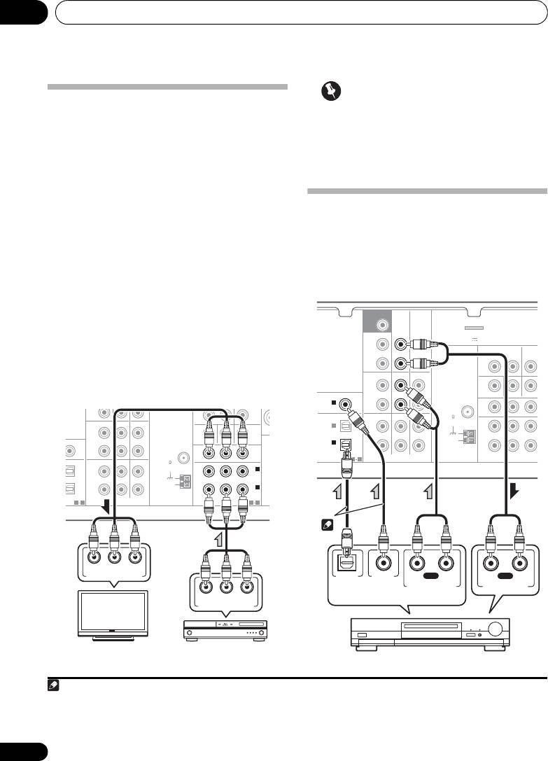
Connecting your equipment03
Important
Using the component video jacks
• If you connect any source component to
Component video should deliver superior
the receiver using a component video
picture quality when compared to composite
input, you must also have your TV
video. A further advantage (if your source and TV
connected to this receiver’s COMPONENT
are both compatible) is progressive-scan video,
VIDEO OUT jacks.
which delivers a very stable, flicker-free picture.
See the manuals that came with your TV and
source component to check whether they are
Connecting other audio
compatible with progressive-scan video.
components
• If necessary, assign the component video
The number and kind of connections depends
inputs to the input source you’ve connected.
1
on the kind of component you’re connecting.
This only needs to be done if you didn’t connect
Follow the steps below to connect a CD-R, MD,
according to the following defaults:
2
DAT, tape recorder or other audio component.
• COMPONENT VIDEO IN 1 – BD
• COMPONENT VIDEO IN 2 – DVD
See The Input Assign menu on page 46 for
• For the audio connection, refer to
Connecting your component with no HDMI
terminal
on page 24.
R
PRE OUT
CD
CD-R/TAPE
DVR/VCR
L
IN
IN
MONITOR OUT
DVD IN BD IN
P
R
P
B
Y
MONITOR
R
OUT
TV/SAT
DVD BD
L
IN
IN
R
COMPONENT VIDEO
26
En
S
SIGNABLE
S
SP
IN
2
(
DVD
)
IN
1
(
BD
)
SIGNABLE
ASSIGNABLE
1 2
AUDIO
E
ANTENNA
FM
UNBAL
75
AM
LOOP
1 2
P
R
B
YP
COMPONENT VIDEO IN
P
R
B
YP
COMPONENT VIDEO OUT
TV
BD player
Note
SURR BACK /
FRONT
HEIGHT
L
(
Single
)
OUT
R
CD
DVR/VCR
L
IN
IN
MONITOR OUT
DVD IN BD IN
P
R
P
B
Y
R
TV/SAT
DVD BD
L
IN
IN
R
1 Note that you must connect digital components to analog audio jacks if you want to record to/from digital components (like
an MD) to/from analog components.
2 If the connection was made using an optical or a coaxial cable, you’ll need to tell the receiver which digital input you connected
the component to (see Choosing the input signal on page 41).
M
TV/SA
COMPONENT VIDEO
T
CD-R/TAPE
DVR/VCR
ADAPTER PORT
(
OUTPUT 5 V 100 mA MAX
)
VIDEO
DVR/VCR
OUT IN
IN
PRE OUT
CD-R/TAPE
COAXIAL
ASSIGNABLE
IN
1
(
CD
)
OPTICAL
IN
1
(
CD-R/TAPE
)
ASSIGNABLE
ASSIG
1 2
AUDIO
N
SUBWOOFER
PRE OUT
ANTENNA
FM
UNBAL
75
IN
2
AM
LOOP
OPTICAL
COAXIAL
R
PLAY
L
R
REC
L
DIGITAL AUDIO OUT
ANALOG AUDIO OUT
ANALOG AUDIO IN
2
Select one
CD-R, MD, DAT, Tape recorder, etc.
VSX-820_SYXCN_En.book 26 ページ 2010年4月12日 月曜日 午後6時52分26
Connecting your equipment 03
27
En
English
Deutsch
Français
Italiano
Nederlands
Español
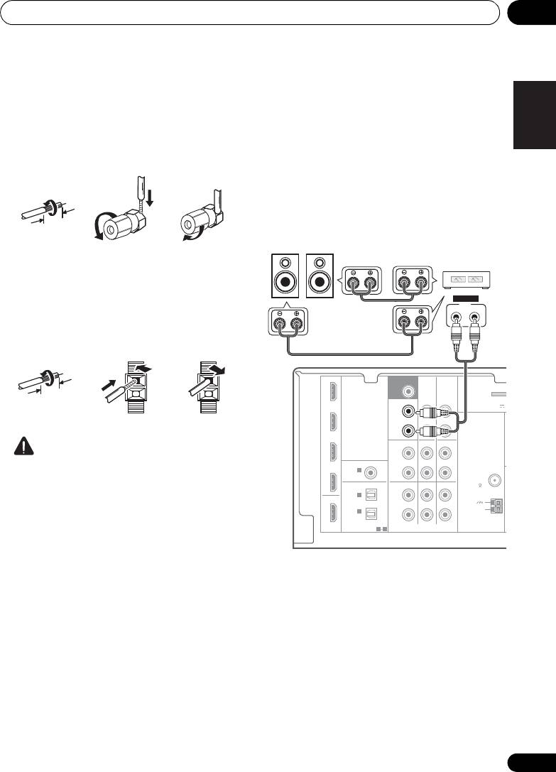
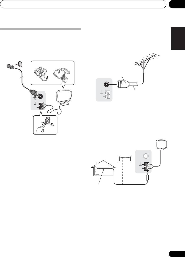
Using external antennas
Connecting antennas
To improve FM reception
Connect the AM loop antenna and the FM wire
Use a PAL connector (not supplied) to connect
antenna as shown below. To improve reception
an external FM antenna.
and sound quality, connect external antennas
(see Using external antennas below).
fig. a fig. b
2
4
ANTENNA
AM
LOOP
3
To improve AM reception
Connect a 5 m to 6 m length of vinyl-coated
wire to the AM antenna terminal without
disconnecting the supplied AM loop antenna.
1
For the best possible reception, suspend
horizontally outdoors.
1 Push open the tabs, then insert one wire
fully into each terminal, then release the tabs
to secure the AM antenna wires.
2 Fix the AM loop antenna to the attached
stand.
To fix the stand to the antenna, bend in the
direction indicated by the arrow (fig. a) then
clip the loop onto the stand (fig. b).
3 Place the AM antenna on a flat surface
and in a direction giving the best reception.
4 Connect the FM wire antenna into the FM
antenna socket.
For best results, extend the FM antenna fully
and fix to a wall or door frame. Don’t drape
loosely or leave coiled up.
ANTENNA
FM
UNBAL
75
Ω
AM
LOOP
One-touch
PAL connector
75 Ω coaxial cable
ANTENNA
FM
UNBAL
75
Ω
AM
LOOP
Outdoor
antenna
Indoor antenna
5 m to 6 m
(vinyl-coated wire)
VSX-820_SYXCN_En.book 27 ページ 2010年4月12日 月曜日 午後6時52分27
Connecting your equipment03
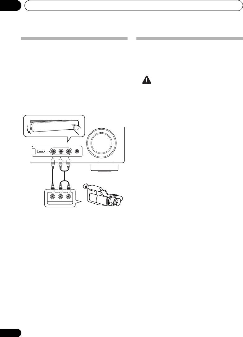
Connecting to the front panel
Plugging in the receiver
Only plug in after you have connected all your
video terminal
components to this receiver, including the
Front video connections are accessed via the
speakers.
front panel using the INPUT SELECTOR or
VIDEO button on the remote control. There are
standard audio/video jacks. Hook them up the
CAUTION
same way you made the rear panel
• Handle the power cord by the plug part. Do
connections.
not pull out the plug by tugging the cord,
•Push down on the PUSH OPEN tab to
and never touch the power cord when your
access the front video connections.
hands are wet, as this could cause a short
circuit or electric shock. Do not place the
unit, a piece of furniture, or other object on
the power cord or pinch the cord in any
other way. Never make a knot in the cord or
tie it with other cables. The power cords
should be routed so that they are not likely
to be stepped on. A damaged power cord
can cause a fire or give you an electric
shock. Check the power cord once in a
while. If you find it damaged, ask your
nearest Pioneer authorized independent
service company for a replacement.
• Do not use any power cord other than the
one supplied with this unit.
• Do not use the supplied power cord for any
purpose other than that described below.
• The receiver should be disconnected by
removing the mains plug from the wall
socket when not in regular use, e.g., when
on vacation.
1 Plug the supplied power cord into the AC
IN socket on the back of the receiver.
2 Plug the other end into a power outlet.
28
En
MASTER
VOLUME
VIDEO INPUT
iPod
iPhone
USB
MCACC
AUDIOLRVIDEO
SETUP MIC
CONTROL ON
/
OFF
LVIDEO
R
AUDIO/VIDEO OUTPUT
This receiver
Video camera
(etc.)
VSX-820_SYXCN_En.book 28 ページ 2010年4月12日 月曜日 午後6時52分
Оглавление
- Contents
- Flow of settings on the receiver
- Before you start
- Controls and displays
- Connecting your equipment
- Basic Setup
- Listening to your system
- The System Setup menu
- Using the tuner
- Making recordings
- Controlling the rest of your system
- Other connections
- Additional information
- Table des matières
- Organigramme des réglages sur le récepteur
- Avant de commencer
- Commandes et affichages
- Raccordement de votre équipement
- Configuration de base
- Écoute de sources à l’aide de votre système
- Menu de configuration du système
- Utilisation du tuner
- Enregistrement
- Commander le reste de votre système
- Autres raccordements
- Informations complémentaires
- Содержание
- Порядок выполнения настроек на ресивере
- Перед началом работы
- Органы управления и индикаторы
- Подключение оборудования
- Основная настройка
- Прослушивание системы
- Меню System Setup (Настройка системы)
- Использование тюнера
- Выполнение записи на внешний источник
- Управление остальными частями системы
- Другие подключения
- Дополнительная информация


