Pioneer DJM-250-W: Operation
Operation: Pioneer DJM-250-W
English
Operation
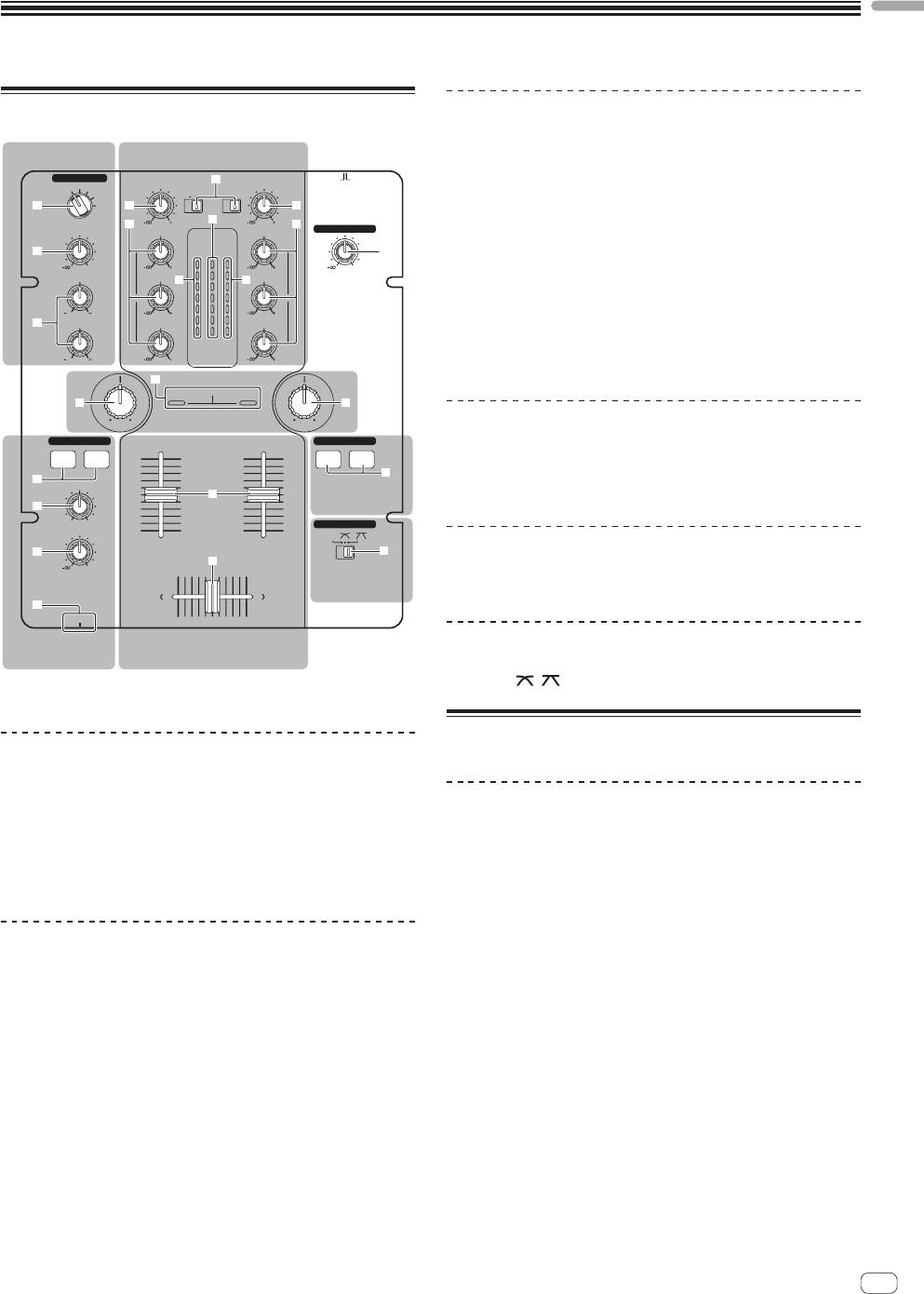
Control panel
Mixer section
Two sets of audio signals can be adjusted separately for basic DJ mixing
MIC/AUX section Mixer section
(page 10).
MIC/AUX
ONOFF
MIC
OFF
9
AUX 1
TRIM
PHONO
PHONO
TRIM
CD
/LINE
CD
/LINE
2 CHANNEL DJ MIXER
9 CD, PHONO/LINE input selector switch
AUX 2
2 a
AUX 3
DJM-250
a
c
a TRIM control
b
9
9
b
LEVEL
HI
HI
MASTER LEVEL
MASTER
3
CH-1 CH-2
1
b EQ (HI, MID, LOW) control
0
9
OVER
OVER
9
0
HI
MID
+4
+4
d d
MID
c Master level indicator
+2
+2
EQ EQ
0
0
-
6
-
6
1212
9
9
d Channel level indicator
-
12
-
12
4
LOW
LOW
LOW
-
18
-
18
dB
dB
e Channel fader
1212
9
LEVEL
9
f Crossfader
g
SOUND COLOR FILTER
hh
LPFHPF LPF HPF
Filter section
Filter section
HEADPHONES
FADER START
CH-1 CH-2
CH-1 CH-2
g SOUND COLOR FILTER indicator
i
5
MIXING
e
Fader start
h SOUND COLOR FILTER control
6
section
MASTERCUE
CROSS FADER
LEVEL
THRU
CH
-
1 CH
-
2
7
j
Fader start section
0
f
Crossfader
section
i CH-1, CH-2 buttons (fader start section)
8
PHONES
Headphones
Mixer section
Crossfader section
section
j THRU, , (crossfader curve selector switch)
1 MASTER LEVEL control (page 10)
About the power switch of this unit
MIC/AUX section
This section handles the sound of microphones or external devices
(computers, portable audio sets, TVs, synthesizers, etc.) (page 12).
To turn the power on
2 MIC, OFF, AUX 1, AUX 2, AUX 3 input selector switch
Set the [ON/OFF] switch on this unit’s rear panel to [ON].
3 LEVEL control (MIC/AUX section)
This turns this unit’s power on (page 5).
4 HI, LOW controls
Headphones section
The sound being input to this unit can be checked over headphones
(page 12).
5 CH-1, CH-2 buttons (headphones section)
6 MIXING control
7 LEVEL control (headphones section)
8 PHONES jack
En
9
5 Move the crossfader f.
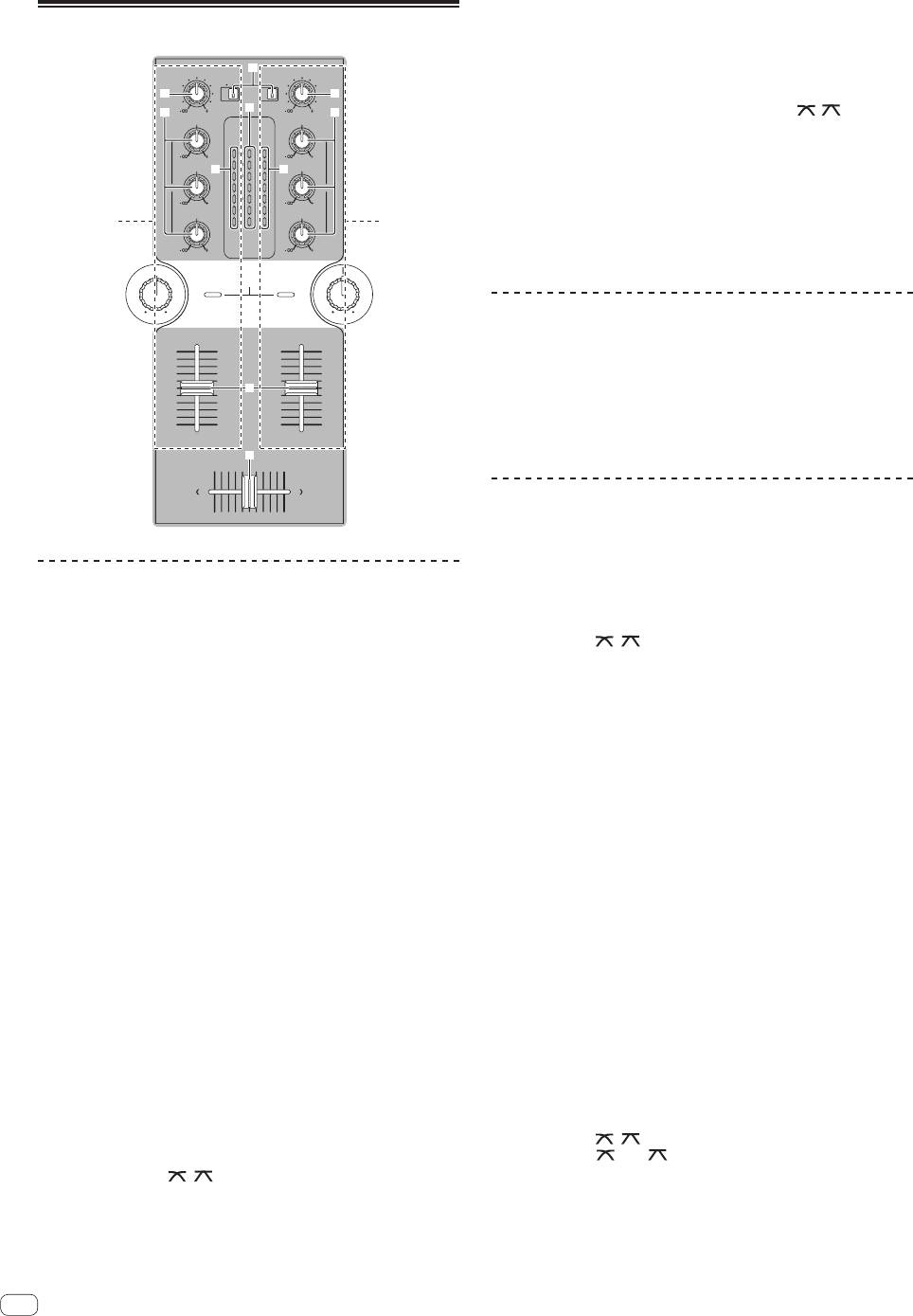
Basic operations (mixer section)
Switch the channel whose sound is output from the speakers.
— Left edge: The [CH-1] sound is output.
— Center position: The sound of [CH-1] and [CH-2] is mixed and
TRIM
9
PHONO
PHONO
TRIM
CD
/LINE
CD
/LINE
output.
a
a
— Right edge: The [CH-2] sound is output.
9
c
b
9
b
! This operation is not necessary when the [THRU,
, ] (cross-
HI
HI
MASTER
fader curve selector) switch is set to [THRU].
CH-1 CH-2
9
OVER
OVER
9
MID
+4
+4
6 Turn the [MASTER LEVEL] control 1 clockwise.
d d
MID
+2
+2
Sound is output from the speakers.
EQ EQ
0
0
-
6
-
6
The master level indicator c on the control panel lights.
9
9
-
12
-
12
LOW
LOW
Adjust [MASTER LEVEL] so that the orange indicator lights at the point
1 2
-
18
-
18
dB
dB
in the track where the volume is loudest (the climax, etc.).
9
LEVEL
9
Be careful that the red indicator does not light, or the sound could be
distorted.
SOUND COLOR FILTER
LPFHPF LPFHPF
Adjusting the sound quality
Turn the [CH-1] 1 or [CH-2] 2 EQ (HI, MID, LOW) control
b.
e
Refer to Specifications on page 14 for the range of sound that can be
adjusted by each control.
! The sound for that range can be turned completely off by turning the
CH
-
1 CH
-
2
control all the way counterclockwise (isolator function).
f
Mixing using the faders
Prepare the unit in advance so that the sound of [CH-1] 1 is being out-
put from the speakers. For instructions on preparation, see Outputting
sound on page 10.
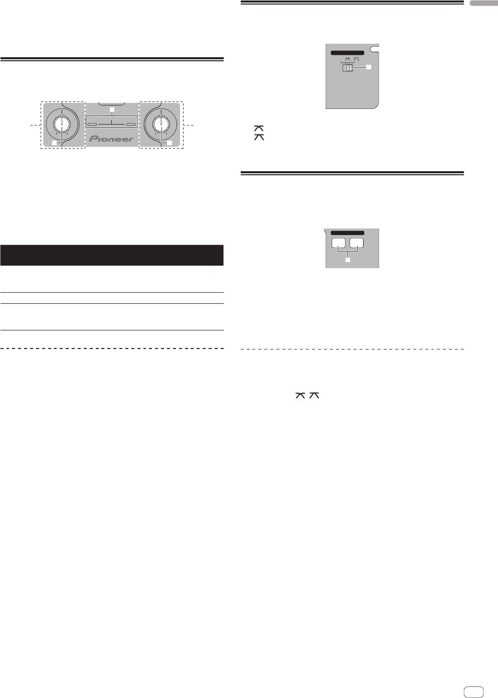
Outputting sound
Mixing using the channel faders
Check that this unit is properly connected to the DJ player, etc., before
outputting sound. For instructions on connections, see Connecting the
input/output terminals on page 6.
1 Set [THRU,
, ] (the crossfader curve selector
switch) j to [THRU].
Set the volume of the powered speakers connected to the [MASTER 1]
and [MASTER 2] terminals to a suitable level. Note that sound will be
2 Switch the [CH-2] 2 [CD, PHONO/LINE] input selector
output at a high volume if the volume is set too high.
switch 9.
For instructions on monitoring the sound, see Monitoring the sound over
headphones (headphones section) on page 12.
3 Turn the [CH-2] 2 [TRIM] control a clockwise.
4 Press the [CH-2] button 5 in the headphones section.
To output the sound of channel 1 [CH-1] 1
The sound of [CH-2] is monitored from the headphones.
To output the sound of channel 2 ([CH-2]) 2, perform the procedure
5 Turn the [MIXING] control 6.
below replacing [CH-1] with [CH-2].
Adjust the monitor volume balance of the sound output from the
[MASTER 1] or [MASTER 2] terminals (the [CH-1] sound) and the [CH-2]
1 Switch the [CH-1] 1 [CD, PHONO/LINE] input selector
sound.
switch 9.
Select the input source for [CH-1] from among the devices connected to
6 Operate the DJ player connected to the [CH-2]
this unit.
terminals.
— [CD]: Selects the DJ player connected to the [CD] terminals.
While checking the sound over the headphones, adjust the tempo of
— [PHONO/LINE]: Selects the device connected to the
[CH-2] track to match the tempo of [CH-1] track.
[PHONO/LINE] terminals.
7 While moving the [CH-2] 2 channel fader to the back,
2 Turn the [CH-1] 1 [TRIM] control a clockwise.
move the [CH-1] 1 channel fader to the front.
Adjusts the audio level input to the [CH-1] terminal.
While checking the sound output from the speakers, operate the chan-
The [CH-1] channel level indicator d lights when audio signals are being
nel faders to substitute the sound of [CH-1] with the sound of [CH-2].
properly input to [CH-1].
Mixing is completed once only the [CH-2] sound is being output from the
Adjust the [TRIM] control so that the orange indicator lights where the
speakers.
track’s volume is highest (at the climax, etc.)
Be careful that the red indicator does not light, or the sound could be
distorted.
Mixing using the crossfader
3 Move the [CH-1] 1 channel fader e away from you.
1 Set [THRU,
, ] (the crossfader curve selector
The level of the sound output from the [CH-1] terminals is adjusted.
switch) j to [ ] or [ ].
4 Switch [THRU, , ] (the crossfader curve selector
2 Operate [CH-2] 2.
switch) j.
Operate as described in steps 2 to 6 under Mixing using the channel
This switches the crossfader’s curve characteristics. For details, see
faders on page 10.
Selecting the crossfader’s curve characteristics (crossfader section) on
page 11.
10
En
3 Move the crossfader f gradually towards the right.
English
While checking the sound output from the speakers, operate the cross-
Selecting the crossfader’s curve
fader to substitute the sound of [CH-1] with the sound of [CH-2].
characteristics (crossfader section)
Mixing is completed once only the [CH-2] sound is being output from the
speakers.
CROSS FADER
THRU
j
Using the filter function (filter
section)
g
SOUND COLOR FILTER
— [THRU]: Choose this when you do not want to use the crossfader.
1 2
— [
]: Set here for a curve that rises gradually.
LPFHPF LPF HPF
— [ ]: Set here for a curve that rises steeply. (When the crossfader
hh
moves away from either the left or right edge, the sound is immedi-
ately output from the opposite side.)
Each channel is equipped with a SOUND COLOR FILTER function by
which filter effects can be achieved simply by turning a large control.
The treble or bass sound can be removed by turning the
[SOUND COLOR FILTER] control h.
Starting playback of a Pioneer DJ
Turn the [CH-1] 1 or [CH-2] 2 [SOUND COLOR FILTER]
player using the fader (fader start
control h.
section)
The effect is applied to the sound and the indicator’s color changes.
The effect type and indicator color differs according to the direction in
FADER START
which the [FILTER] control is turned, as shown on the table below.
CH-1 CH-2
Direction of
Description of effect Indicator
rotation
i
Applies the effect of the
Left
treble sound fading out.
Red (flashing)
If you connect a Pioneer DJ player using a control cable (supplied with
(LPF: low pass filter)
a DJ player), you can start playback of control other operations of the DJ
player with the fader of this unit.
Center — Orange (lit)
The fader start function can only be used when connected to a Pioneer
Applies the effect of the bass
DJ player.
Right
sound fading out.
Green (flashing)
Connect this unit and Pioneer DJ player beforehand. For instructions on
(HPF: high pass filter)
connections, see Connecting the input/output terminals on page 6.
Mixing using the SOUND COLOR FILTER
To start playback using the channel
control
faders
Prepare the unit in advance so that the sound of [CH-1] 1 is being out-
put from the speakers. For instructions on preparation, see Outputting
1 Set [THRU, , ] (the crossfader curve selector
sound on page 10.
switch) j to [THRU].
For instructions on monitoring the sound, see Monitoring the sound over
headphones (headphones section) on page 12.
2 Press the [CH-1] or [CH-2] button i in the fader start
section.
1 Operate the crossfader and [CH-2] 2.
Turn the fader start function on.
Operate as described in steps 2 to 6 under Mixing using the channel
faders on page 10.
3 Move the channel fader e to the very front.
2 Turn the [CH-2] 2 [SOUND COLOR FILTER] control h
4 Set the cue on the DJ player.
fully clockwise.
The DJ player pauses playback at the cue point.
3 Move the [CH-2] 2 channel fader e away from you.
5 Move the channel fader e away from you.
Playback starts on the DJ player.
4 While turning the [CH-1] 1 [SOUND COLOR FILTER]
! If you set the channel fader back to the original position, the player
control h counterclockwise from the center, turn the
instantaneously returns to the cue point already set and pauses
playback (back cue).
[CH-2] 2 [SOUND COLOR FILTER] control h towards the
center.
While checking the sound output from the speakers, operate the
[SOUND COLOR FILTER] controls h and replace the [CH-1] and [CH-2]
sound.
Move the [CH-1] 1 channel fader e towards the front. Mixing is com-
pleted once only the sound of [CH-2] is output from the speakers.
En
11
To start playback using the crossfader
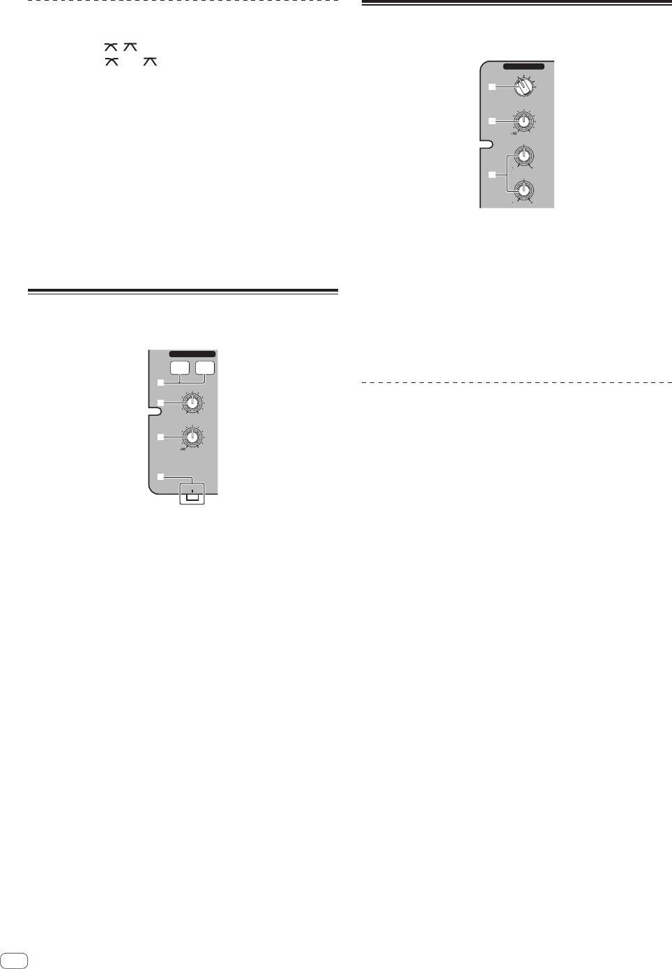
Using a microphone or external
device (MIC/AUX section)
1 Set [THRU, , ] (the crossfader curve selector
switch) j to [ ] or [ ].
MIC/AUX
MIC
OFF
AUX 1
AUX 2
2 Press the [CH-1] or [CH-2] button i in the fader start
2
AUX 3
section.
LEVEL
Turn the fader start function on.
3
0
3 Move the crossfader f.
HI
Move the crossfader to the opposite edge from the channel for which
you want to use the fader start function.
1212
4
LOW
4 Set the cue on the DJ player.
The DJ player pauses playback at the cue point.
1212
5 Move the crossfader f.
Playback starts on the DJ player.
1 Switch the [MIC, OFF, AUX 1, AUX 2, AUX 3] input
! If you set the crossfader back to the original position, the player
selector switch 2.
instantaneously returns to the cue point already set and pauses
— [MIC]: The microphone connected to the [MIC] terminal is
playback (back cue).
selected.
— [AUX1–3]: Selects the external device connected to the [AUX1–3]
terminals.
Monitoring the sound over
2 Turn the [LEVEL] control 3 in the MIC/AUX section
headphones (headphones section)
clockwise.
The sound of the microphone or external device is output from the
HEADPHONES
speakers.
CH-1 CH-2
5
MIXING
6
Adjusting the sound quality
MASTERCUE
LEVEL
Turn the [HI] or [LOW] control 4 in the MIC/AUX section.
7
Refer to Specifications on page 14 for the range of sound that can be
0
adjusted by each control.
8
PHONES
1 Connect headphones to the [PHONES] terminal.
For instructions on connections, see Connecting the input/output termi-
nals on page 6.
2 Press the [CH-1] or [CH-2] button 5 in the
headphones section.
Select the channel you want to monitor.
— [CH-1]: The sound of [CH-1] is monitored.
— [CH-2]: The sound of [CH-2] is monitored.
! This operation is not necessary to monitor the [MASTER 1] or
[MASTER 2] (master channel) sound.
3 Turn the [MIXING] control 6.
— When turned counterclockwise: The volume of [CH-1] and [CH-2]
becomes relatively louder.
— Center position: The volume of the [CH-1] and [CH-2] sound is
the same level as the [MASTER 1] and [MASTER 2] sound.
— When turned clockwise: The volume of [MASTER 1] and
[MASTER 2] become relatively louder.
4 Turn the [LEVEL] control 7 in the headphones section
clockwise.
Sound is output from the headphones.
! When the [CH-1] or [CH-2] button in the headphones section is
pressed again, monitoring is canceled.
! [MASTER 1] and [MASTER 2] monitoring cannot be canceled.
12
En
Оглавление
- Contents
- Before start
- Connections
- Operation
- Additional information
- Sommaire
- Informations préliminaires
- Raccordements
- Fonctionnement
- Informations supplémentaires
- Inhalt
- Vor der Inbetriebnahme
- Anschlüsse
- Bedienung
- Zusätzliche Informationen
- Indice
- Prima di cominciare
- Collegamenti
- Impiego
- Informazioni aggiuntive
- Inhoud
- Alvorens te beginnen
- Aansluitingen
- Bediening
- Aanvullende informatie
- Contenido
- Antes de empezar a usar la unidad
- Conexiones
- Operación
- Información adicional
- Содержание
- До начала
- Подключения
- Управление
- Дополнительная информация


