Pioneer DJM-2000: Operations
Operations: Pioneer DJM-2000
English
Operations
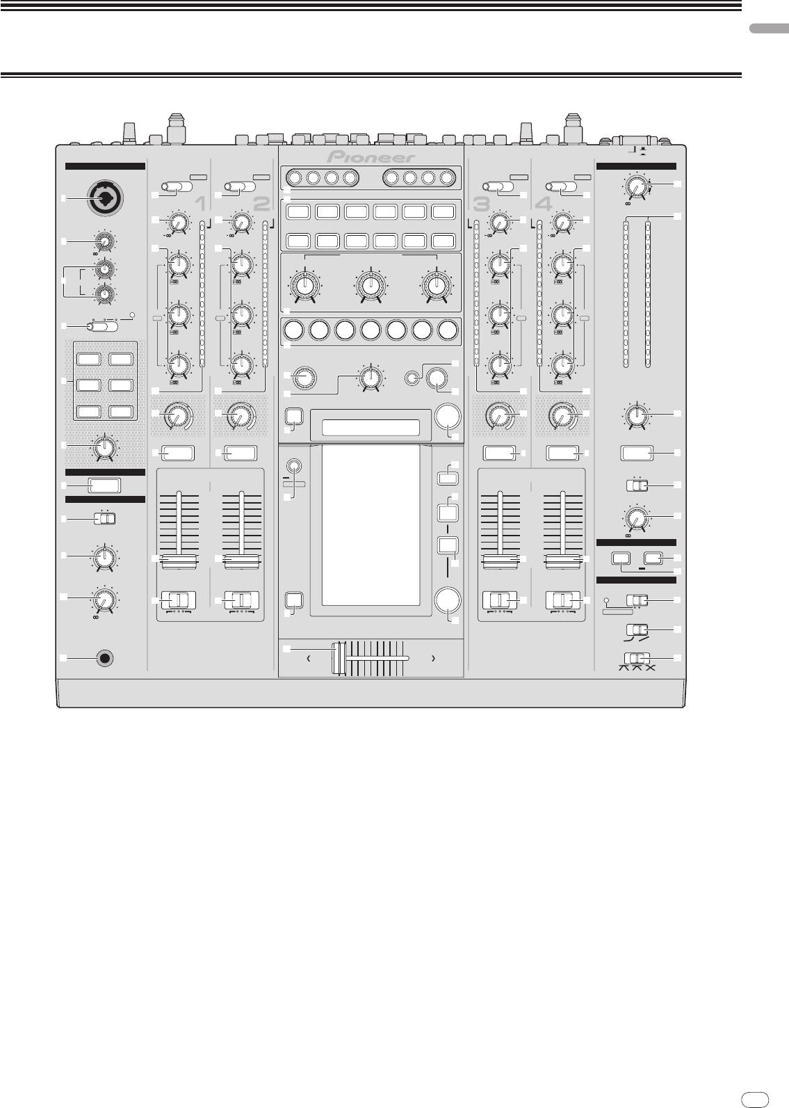
Control Panel
En
11
DRB1497-B
11
POWER
OFF
ON
MIC
MASTER
CD
CD
CD
CD
/DIGITAL PHONO
USB 1/2
/DIGITAL LINE
USB 3/4
1 2 3 4
CH
SELECT
MIC
A B M
/DIGITAL LINE
USB 5/6
/DIGITAL PHONO
USB 7/8
y
j
1
c
c
c
c
k
TRIM
TRIM
TRIM
TRIM
-
0
MULT I TAP
REV
OVER
OVER
DELAY
DELAY
ROLL
ROLL
TRANS
GATE
OVER
OVER
d
d
d
d
z
EFFECT SELECT
OVER
MIC
+
9
10
+
9
10
10
+
9
SLIP
SEND/
10
+
9
10
2
LEVEL
ECHO
REVERB
FILTER
PHASER
HI
7
HI
7
ROLL
RETURN
7
HI
7
HI
e e ee
7
-
0
4
4
EFFECT FREQUENCY
4
4
4
2
2
LOW
MID
HI
2
2
2
HI
1
1
1
1
1
3
EQ
-12
+12
-26/
+
6
0
-26/
+
6
0
0
-26/
+
6
0
-26/
+
6
0
LOW
MID
- 1
MID
- 1
- 1
MID
- 1
MID
- 1
-12
+12
- 2
- 2
MIN MAX
MIN MAX
MIN MAX
- 2
- 2
- 2
TALK
OFF ON OVER
EQ/
- 3
EQ/
- 3
l
- 3
EQ/
- 3
EQ/
- 3
ISO
ISO
ISO
ISO
- 5
- 5
- 5
- 5
- 5
4
-26/
+
6
- 7
-26/
+
6
- 7
1/8
1/4 1/2 3/4 1/1 2/1 4/1
- 7
-26/
+
6
- 7
-26/
+
6
- 7
- 10
- 10
- 10
- 10
- 10
INST FX
LOW
LOW
m
LOW
LOW
- 15
- 15
- 15
- 15
- 15
NOISE JET
- 24
- 24
TIME
LEVEL/DEPTH
AUTO
- 24
- 24
- 24
/TAP
p
dB
dB
dB
dB
LR
dB
n
5
-26/
+
6
-26/
TA P
ZIP HPF
+
6
-26/
+
6
-26/
+
6
f
f
o
MIN
MAX
q
f
f
FILTER
FILTER
ON/OFF
FILTER
FILTER
BALANCE
CRUSH LPF
g
g
CUE
g
g
A
PARAMETER
MINMAX
MINMAX
7
MINMAX
MINMAX
L
R
r
6
7
CUE
CUE
LIVE
7
SAMPLER
CUE
7
CUE
7
CUE
7
MIN
MAX
t
LINK
MONO
STEREO
UTILITY
MIDI
7
CUE
WAKE UP
B
10
HEADPHONES
s
u
10
9
9
BOOTH MONITOR
MONO SPLIT STEREO
8
8
7
MIX
7
8
C
6
6
5
5
MIXING
4
4
0
3
REMIX
3
MIDI
2
2
ON/OFF
START/STOP
9
1
1
h
0
h
h
0
h
D
v
SNAPSHOT
CUE
MASTER
E
LEVEL
CURVE SETTING
ON/OFF
CH EQ
a
i
i
CUE
i
i
F
ISOLATOR
EQ
-
0
AB
THRU
AB
THRU
7
AB
THRU
AB
THRU
w
CH FADER
CROSS FA DER ASSIGN
CROSS FADER ASSIGN
G
PHONES
x
PROFESSIONAL MIXER
CROSS FADER
b
AB
DJM-
2000
H
1 Microphone input jack (page 13)
h Channel Fader (page 12)
2 MIC LEVEL (page 13)
i CROSS FADER ASSIGN (A, THRU, B) (page 12)
3 EQ (HI, LOW) (page 13)
j CH SELECT (page 16)
4 OFF, ON, TALK OVER (page 13)
k EFFECT SELECT (page 16)
5 INST FX (page 15)
l EFFECT FREQUENCY (HI, MID, LOW) (page 16)
6 PARAMETER (page 15)
m Beat buttons (page 16)
7 CUE (page 12)
n TIME (page 16)
8 MONO SPLIT, STEREO (page 12)
o LEVEL/
DEPTH (page 16)
9 MIXING (page 12)
p AUTO/TAP (page 16)
a LEVEL (page 12)
q TAP (page 16)
b PHONES (page 12)
r ON/
OFF (BEAT EFFECT) (page 16)
c CD/DIGITAL, PHONO, LINE, USB */* (page 12)
s LIVE SAMPLER (UTILITY, WAKE UP) (page 15, page 24)
d TRIM (page 12)
t MIDI (page 16)
e EQ/ISO (HI, MID, LOW) (page 12)
u MIX (page 14)
f Channel Level Indicator (page 12)
v REMIX (page 14)
g FILTER (page 15)
w ON/
OFF (TOUCH PANEL EFFECT) (page 14)

12
En
DRB1497-B
x Crossfader (page 12)
Basic Operation
y MASTER (page 12)
z Master Level Indicator (page 12)
Outputting sound
A BALANCE (page 13)
B MONO, STEREO (page 13)
1 Press [POWER].
Turn on the power of this unit.
C BOOTH MONITOR (page 13)
2 Switching the [CD/DIGITAL, PHONO, LINE, USB */*] switch
D START/
STOP (SNAPSHOT) (page 16)
Select the input sources for the different channels from among the devices con-
E ON/
OFF (MIDI) (page 16)
nected to this unit.
— [CD/DIGITAL]: Selects the DJ player connected to the [CD] terminals. To
F CH EQ (ISOLATOR, EQ) (page 12)
select the DJ player connected to the [DIGITAL IN] terminal, set the [CD,
DIGITAL] switch on the rear panel to [DIGITAL].
G CH FADER (
, ) (page 13)
— [PHONO]: Selects the analog player connected to the [PHONO]
terminals.
H CROSS FADER (
, , ) (page 13)
— [LINE]: Selects the cassette deck or CD player connected to the [LINE]
terminals.
— [USB */*]: Selects the sound of the computer connected to the [USB]
port.
3 Rotate [TRIM].
Adjusts the level of audio signals input in each channel.
The corresponding channel level indicator lights when audio signals are being
properly input to that channel.
4 Set the channel fader to the inner position.
Adjusts the level of audio signals output in each channel.
5 Switch the [CROSS FADER ASSIGN (A, THRU, B)] switch.
Switches the output destination of each channel.
— [A]: Assigns to [A] (left) of the crossfader.
— [B]: Assigns to [B] (right) of the crossfader.
— [THRU]: Choose this when you do not want to use the crossfader. (The
signals do not pass through the crossfader.)
6 Set the crossfader.
This operation is not necessary when [CROSS FADER ASSIGN (A, THRU, B)] is set
to [THRU].
7 Turn the [MASTER] control.
Audio signals are output from the [MASTER1] and [MASTER2] terminals.
The master level indicator lights.
Adjusting the sound quality
Turn the [EQ/ISO (HI, MID, LOW) ] controls for the individual
channels.
Refer to Specifications on page 28 for the range of sound that can be adjusted by
each control.
Switching the [EQ/ISO (HI, MID, LOW)] function.
Switch the [CH EQ (ISOLATOR, EQ)] switch.
— [ISOLATOR]: The isolator function is set. The indicator lights.
— [EQ]: The equalizer function is set.
Monitoring sound with headphones
1 Connect headphones to the [PHONES] jack.
2 Press [CUE] for the channel to be monitored.
3 Switch the [MONO SPLIT, STEREO] switch.
— [MONO SPLIT]: The sound of the channel for which [CUE] is pressed is
output from the headphones output’s left channel, while the sound of
[MASTER] is output from the right channel.
— [STEREO]: The sound of the channel for which [CUE] is pressed is output
in stereo from the headphones.
4 Turn the [MIXING] control.
This adjusts the balance of the monitor volume between the sound of the channel
for which [CUE] is pressed and the [MASTER] channel sound.
5 Turn the [LEVEL] control for [HEADPHONES].
Sound is output from the headphones in the channel selected by [CUE].
! Monitoring is canceled when [CUE] is pressed again.
! When [LIVE SAMPLER] is turned on, [CUE] button for the TOUCH PANEL
EFFECT and [CUE] button for the [LINK] cannot be pressed simultaneously.
12
Monitoring the sound of the computer
Using a microphone
English
1 Connect headphones to the [PHONES] jack.
1 Connect the microphone to the microphone input jack.
2 Connect a computer on which rekordbox is installed.
2 Set [OFF, ON, TALK OVER] to [ON] or [TALK OVER].
For instructions on connections, see Connecting input terminals on page 7.
— [ON]: The indicator lights.
— [TALK OVER]: The indicator flashes.
3 Selecting the track to be monitored with rekordbox
! When set to [TALK OVER], sound other than that from the [MIC] terminal is
attenuated by 20 dB (default value) when sound of –15 dB (default value) or
4 Press [CUE] button for [LINK].
greater is input to the microphone.
The track selected with rekordbox is output from the headphones.
! Monitoring is canceled when [CUE] is pressed again.
3 Turn the [MIC LEVEL] control.
! The same operation as at Monitoring sound with headphones (steps 3 to 5)
This adjusts the audio level output from the [MIC] terminal.
can be performed.
! Pay attention that rotating to the extreme right position outputs a very loud
sound.
Switching the fader curve
4 Input audio signals to the microphone.
Adjusting the sound quality
Select the channel fader curve characteristics.
Turn the [EQ (HI, LOW)] control for [MIC] channel.
Switch the [CH FADER (
, )] switch.
Refer to Specifications on page 28 for the range of sound that can be adjusted by
— [ ]: The curve rises suddenly at the back side.
each control.
— [ ]: The curve rises gradually (the sound gradually increases as the
channel fader is moved away from the front side).
Switching between monaural and stereo audio
Select the crossfader curve characteristics.
This switches the sound output from the [MASTER1], [MASTER2], [BOOTH], [REC
OUT], [PHONES], [DIGITAL OUT] and [USB] terminals between monaural and
Switch the [CROSS FADER (
, , )] switch.
stereo.
— [ ]: Makes a sharply increasing curve (if the crossfader is moved away
from the [A] side, audio signals are immediately output from the [B]
Switch the [MONO, STEREO] switch.
side).
— [MONO]: Outputs monaural audio.
— [ ]: Makes a curve shaped between the two curves above and below.
— [STEREO]: Outputs stereo audio.
— [ ]: Makes a gradually increasing curve (if the crossfader is moved
away from the [A] side, the sound on the [B] side gradually increases,
Adjusting the L/
R balance of audio
while the sound on the [A] gradually decreases).
The left/
right balance of the sound output from the [MASTER1], [MASTER2],
[BOOTH], [REC OUT], [PHONES], [DIGITAL OUT] and [USB] terminals can be
Starting playback on a DJ player using the fader
adjusted.
(fader start)
1 Set the [MONO, STEREO] switch to [STEREO].
When connected to a Pioneer DJ player by LAN cable (included with this unit) or
2 Rotate [BALANCE].
control cord (included with the DJ player), operations such as starting playback
The L/
R balance of audio varies according to the rotation direction and position
on the DJ player can be controlled with this unit’s fader.
of the [BALANCE] control.
Connect this unit and Pioneer DJ player beforehand. For instructions on connec-
! Rotating to the rightmost position outputs only the right sound of stereo
tions, see Connecting input terminals on page 7.
audio. Rotating to the leftmost position outputs only the left sound of stereo
audio.
Start playback using the channel fader
1 Set [CROSS FADER ASSIGN (A, THRU, B)] to [THRU].
Audio is output from the [BOOTH] terminal
2 Set [FADER START] to [ON].
Rotate [BOOTH MONITOR].
For instructions on setting, see Changing the settings on page 24.
Adjusts the level of audio signals output at the [BOOTH] terminal.
3 Set the channel fader to the outermost position.
4 Set the cue on the DJ player.
The DJ player pauses playback at the cue point.
5 Set the channel fader to the inner position.
Playback starts on the DJ player.
! If you set the channel fader back to the original position, the player instanta-
neously returns to the cue point already set and pauses playback (back cue).
Start playback using the crossfader
1 Set [CROSS FADER ASSIGN (A, THRU, B)] to [A] or [B].
2 Set [FADER START] to [ON].
For instructions on setting, see Changing the settings on page 24.
3 Set the crossfader.
Set to the edge opposite the side on which the channel you want to use with the
fader start function is set.
4 Set the cue on the DJ player.
The DJ player pauses playback at the cue point.
5 Set the crossfader.
Playback starts on the DJ player.
! If you set the crossfader back to the original position, the player instanta-
neously returns to the cue point already set and pauses playback (back cue).
En
13
DRB1497-B
1312
14
En
DRB1497-B
Advanced Operations
About PRO DJ LINK
When a PRO DJ LINK-compatible Pioneer DJ player (CDJ-2000, CDJ-900 etc.),
a computer on which rekordbox is installed and this unit are connected by LAN
cable, the PRO DJ LINK functions below can be used.
For more details on the PRO DJ LINK function, also refer to the DJ player’s han-
dling instructions and rekordbox’s operating instructions.
For instructions on connections, see Connecting input terminals on page 7.
! Up to four DJ players can be connected. Up to two computers can be
connected.
! Connect the DJ players to the [LINK] terminal ([CH1] to [CH4]) with the same
number as the channel to which the audio cables are connected.
! Connect the computers to the [COMPUTER 1] or [COMPUTER 2] terminal.
SD & USB Export
rekordbox music files and management data on SD memory cards/
USB devices
connected to a CDJ-2000, CDJ-900, etc., can be transferred between DJ players.
rekordbox LINK Export
This function lets you transfer rekordbox music files and management data
directly, eliminating the bother of exporting the data to an SD memory card/
USB
device.
LIVE SAMPLER
The sound input to the [MIC] terminal or output from the [MASTER] terminals
can be sampled and played on a DJ player.
LINK MONITOR
With this function, rekordbox music files stored on the computer can be quickly
monitored over the headphones.
STATUS INFORMATION
This function informs the DJ players of the connected channel status (on-air
status, channel number, etc.).
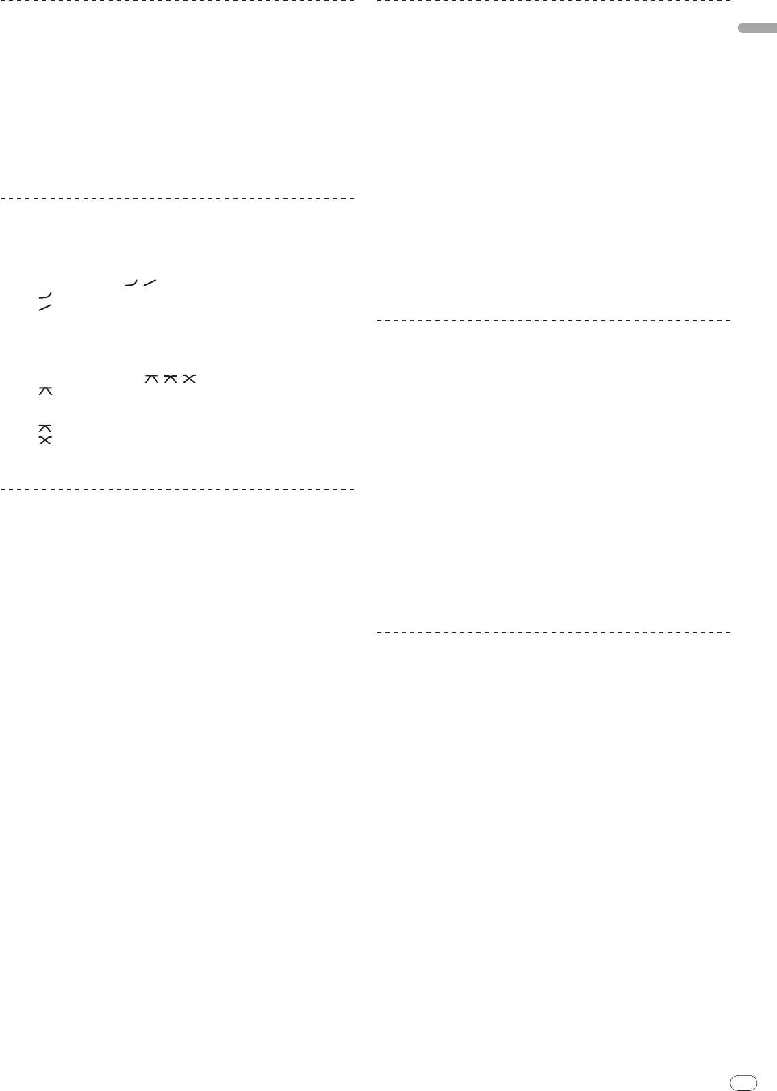
FREQUENCY MIX
The currently playing sound is divided into seven frequency bands that are dis-
played graphically. Fader control on the touch panel makes it easier to grasp the
details and mix two channels or swap instruments (parts).
14
1
2
3
4
5
6
To mix [CH2] and [CH3]:
Prepare this unit in advance so that the sound of [CH3] is being output from the
[MASTER] terminals.
1 Set the [CROSS FADER ASSIGN (A, THRU, B)] switches for [CH2]
and [CH 3] to [THRU].
! Set the [CROSS FADER ASSIGN (A, THRU, B)] switches of the channels to be
mixed to [THRU].
! When using the crossfader, it is recommended to set it to the center position.
2 Press [MIX].
The [FREQUENCY MIX] screen appears on the touch panel.
3 Press the channel assign buttons to select [CH2] for the left
side, [CH3] for the right side.
The volume levels for the individual frequency bands of the sound playing in
[CH3] are displayed on the right half of the touch panel.
4 Press all the [ >> ] buttons.
All the touch faders move to the right edge.
5 Press [ON/
OFF].
This turns the effect on.
[ON/
OFF] flashes when the effect is turned on.
6 Move the channel fader for [CH2] to the back side.
The volume levels for the individual frequency bands of the sound playing in
[CH2] are displayed on the left half of the touch panel.
7 Move the touch fader to the left side.
The sound of the frequency bands whose crossfaders have been moved is mixed
and output.
! The effect turns off when [ON/
OFF] is pressed again.
! To switch from the [FREQUENCY MIX] to the [SIDECHAIN REMIX] mode, first
press the [ON/
OFF] button to turn the effect off, then press [REMIX].
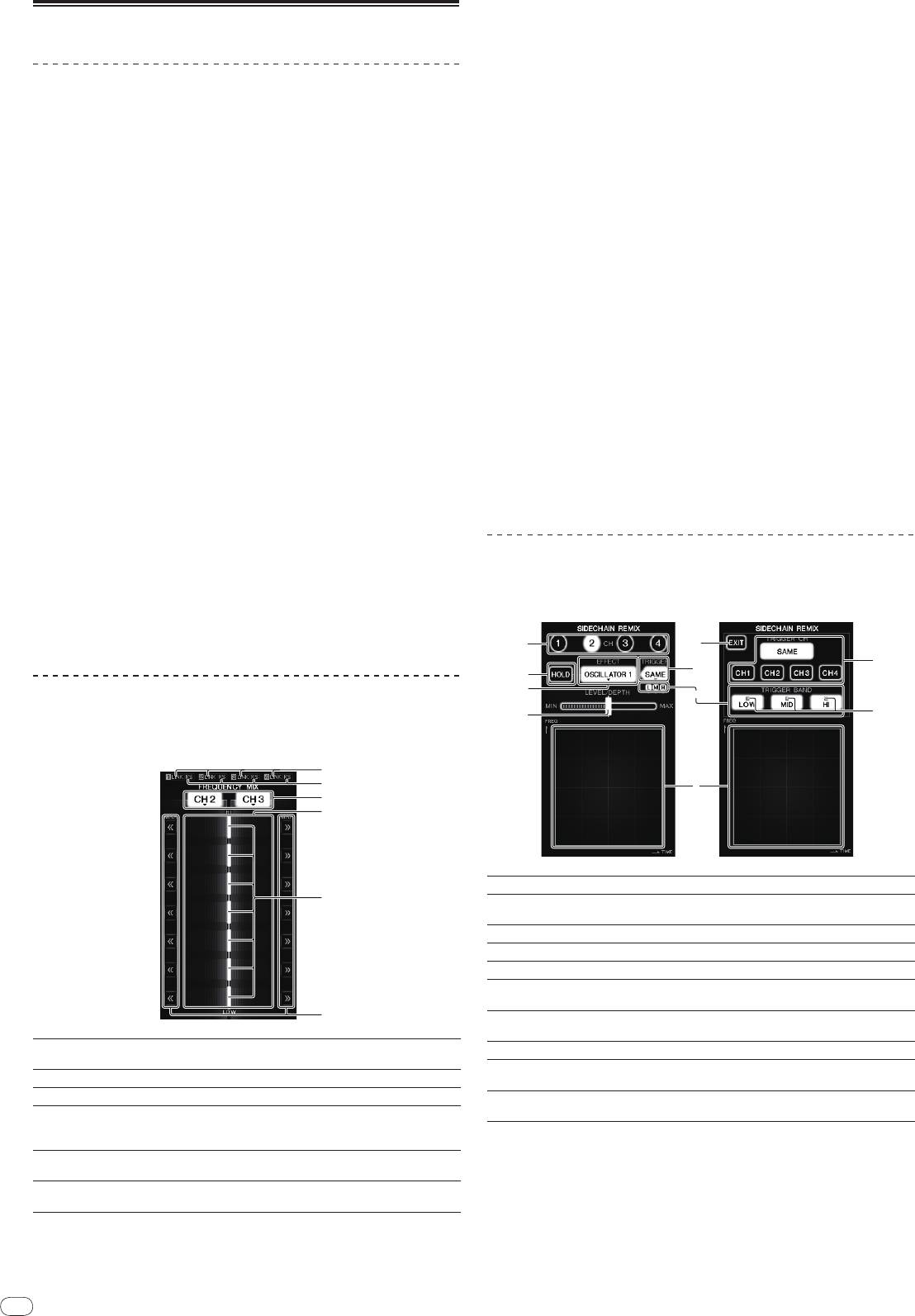
SIDECHAIN REMIX
When this function is used, the sound of the specified frequency band for the
specified channel can be used as the trigger to apply effects to the sounds of
other channels.
These light when DJ players are properly connected to the
1
LINK
[LINK] terminals.
2
FS
These light when the fader start function is turned on.
3
Channel assign buttons These select the channels to be mixed.
The input volume level to this function is displayed in a light
4
Volume level display
color, the output volume level from this function is displayed
in a dark color.
These adjust the volume balance of the channels to be
5
Touch fader
mixed for the separate frequency bands.
These move the touch fader immediately to the left or right
6
<< >>
edge.
5
3
7
4
9
a
1
6
2
8
1
CH
This selects the channel to which the effect is applied.
This holds the effect’s parameter information (the position
2
HOLD
at which the control area was touched).
3
EFFECT
This selects the type of effect.
4
LEVEL/
DEPTH
Use this to adjust the amount of the effect applied.
5
EXIT
Use this to close the [TRIGGER] menu.
TRIGGER (SAMPLING/
6
Use this to open the [TRIGGER] menu.
TRIGGER)
Use these to select the frequency band to be used as the
7
TRIGGER BAND
trigger.
8
Control area Use this to change the effect’s parameters.
TRIGGER CH (SAM-
9
This selects the channel to be used as the effect trigger.
PLING/
TRIGGER CH)
These flash according to the automatically detected rhythm
a
Trigger indicators
for the different frequency bands.
To set the channel for sampling and triggering to [CH3]
and mix the sampled sound with the sound of [CH2] for
output:
Prepare this unit in advance so that the sound of [CH2] is being output from the
[MASTER] terminals.
1 Press [REMIX].
The [SIDECHAIN REMIX] screen appears on the touch panel.
2 Press the [2] button in the [CH] section.
This selects the channel to which the effect is applied.
English
3 Press [EFFECT] and select [SAMPLER].
This selects the type of effect.
Effect Name Descriptions
Sound is created inside this unit, mixed to the sound of the channel
OSCILLATOR1 – 4
selected in the [CH] section, then output according to the [TRIGGER CH
(SAMPLING/
TRIGGER CH)] trigger.
The sound of the channel selected at [TRIGGER CH (SAMPLING/
TRIG-
GER CH)] is sampled, mixed to the sound of the channel selected in the
SAMPLER
[CH] section, then output according to the [TRIGGER CH (SAMPLING/
TRIGGER CH)] trigger.
The pitch of the sound of the channel selected in the [CH] section is
PITCH
changed, mixed with the channel selected in the [CH] section, then out-
put according to the [TRIGGER CH (SAMPLING/
TRIGGER CH)] trigger.
The sound input at [CH] is output according to the [TRIGGER CH (SAM-
GATE
PLING/
TRIGGER CH)] trigger.
! It is not possible to select multiple effects simultaneously.
4 Press [TRIGGER (SAMPLING/
TRIGGER)].
The [TRIGGER] menu appears.
5 At [TRIGGER CH (SAMPLING/
TRIGGER CH)], select [CH3].
This selects the channel to be used as the effect trigger.
! When [SAME] is pressed, the same channel as the one selected in the [CH]
section is selected as the trigger.
6 At [TRIGGER BAND], press [MID] and [HI].
This selects the frequency band set as the effect trigger.
Only [LOW] (the bass sound) is selected.
7 Press [ON/
OFF].
This turns the effect on.
[ON/
OFF] flashes when the effect is turned on.
8 Touch the control area.
[ ] appears at the point at which the panel was touched.
The [CH3] sound at the point in the control area that was touched is sampled.
Triggered by the low frequency sound of [CH3], the sampled sound is mixed with
the sound of [CH2] (which is continuing to play normally) and output from the
[MASTER] terminals.
The effect changes when the position touched in the control area is changed.
! The effect turns off when [ON/
OFF] is pressed again.
! The sampled sound is only valid while the control area is being touched.
! To switch from the [SIDECHAIN REMIX] to the [FREQUENCY MIX] mode, first
press the [ON/
OFF] button to turn the effect off, then press [MIX].
Using [HOLD]
When [HOLD] is turned on, effect’s parameter information is held even if the effect is
turned off. The parameter information is cleared when [HOLD] is turned off.
! The parameter information and sampled sound are cleared when the effect is
switched.
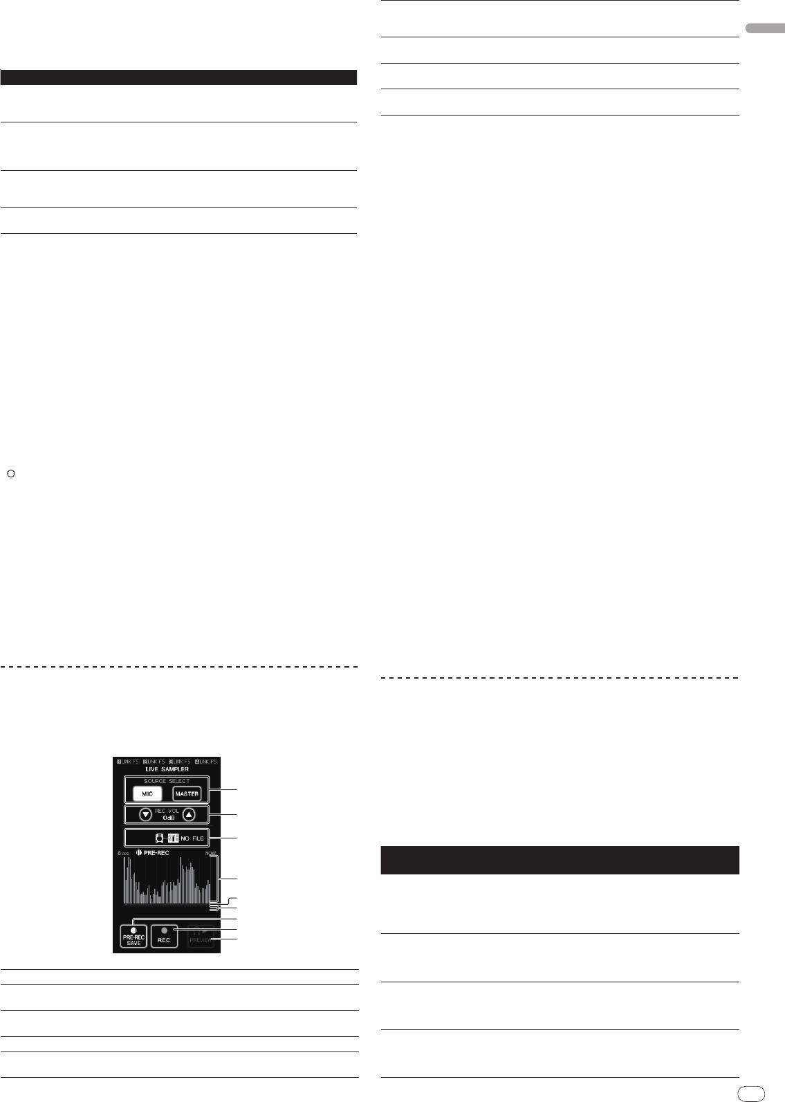
LIVE SAMPLER
The sound input to the [MIC] terminal or the sound output from the [MASTER]
terminals can be sampled and played on a PRO DJ LINK–compatible Pioneer DJ
player.
Connect this unit and PRO DJ LINK-compatible Pioneer DJ player in advance.
For instructions on connections, see Connecting input terminals on page 7.
En
15
DRB1497-B
1514
1
2
3
4
5
6
7
8
9
The sound is played from the position at which the touch
6
Slider
panel was touched.
This is only displayed when previewing the sound.
The sound is sampled from a point 8 seconds before the
7
PRE-REC SAVE
button was pressed.
The sound is sampled for up to 8 seconds from the point at
8
REC (REC STOP)
which the button is pressed.
Use this to preview the sampled sound over the head-
9
PREVIEW (STOP)
phones.
Sampling the sound being played
1 Press [LIVE SAMPLER].
The [LIVE SAMPLER] screen appears on the touch panel.
2 Press [MIC] or [MASTER] in the [SOURCE SELECT].
This selects the channel to be sampled.
3 Press [REC (REC STOP)].
The sound of the channel selected at step 2 is sampled from the point at which
[REC (REC STOP)] was pressed.
! Sampling is possible for up to 8 seconds.
! Sampling stops automatically once 8 seconds have elapsed after [REC
(REC STOP)] was pressed.
4 Press [REC (REC STOP)].
Sampling stops. The sample saving screen is displayed.
Sampling the sound from the point 8 seconds before
1 Press [LIVE SAMPLER].
The [LIVE SAMPLER] screen appears on the touch panel.
2 Press [MIC] or [MASTER] in the [SOURCE SELECT].
This selects the channel to be sampled.
3 Press [PRE-REC SAVE].
The sound for the channel selected in step 2 is sampled from the point 8 seconds
before [PRE-REC SAVE] was pressed.
! Sampling is possible for up to 8 seconds.
Previewing the sampled sound
1 Press the [CUE] button to the left of the touch panel.
2 Press [PREVIEW (STOP)].
The position being played is displayed at the playing address and slider displays.
! When the touch panel’s slider is touched, the sampled sound is played from
that position.
Playing the sampled sound on the DJ player
Use PRO DJ LINK to access this unit from the DJ player.
The sampled sound (audio file) can be loaded and played on the DJ player.
INST FX
This effect changes in association with the [FILTER] controls for the individual
channels.
1 Press one of the [INST FX] buttons.
This selects the type of effect.
The button that was pressed flashes.
! The same effect is set for [CH1] to [CH4].
2 Turn the [FILTER] control.
The effect is applied to the channel(s) for which the control(s) was (were)
pressed.
PARAMETER
Effect Name Descriptions
FILTER (parameter 1)
(parameter 2)
White noise generated
Sets the cut-off
inside this unit is mixed
frequency for the
Sets the volume of the
NOISE
in to the sound of the
filter through which the
white noise.
channel via the filter
white noise passes.
and output.
Sets the balance
Lowers the pitch of the
Sets the amount of
between the original
ZIP
channel’s sound for
pitch shifting for lower-
sound and the effect
output.
ing the pitch.
1
SOURCE SELECT
Select the source to be sampled here.
sound.
Use these to adjust the volume for recording.
The further the control
2
REC VOLUME
Changes the channel’s
Sets the degree by
The volume can be adjusted in the range –9 dB to +9 dB.
is turned clockwise,
CRUSH
sound to a crushed
which the input sound
the more the effect is
This indicates this unit’s status and whether or not sam-
sound for output.
is crushed.
3
Status indicator
stressed.
pling data is available.
The further the control
4
Waveform display This displays the sound as a waveform.
Adds a flanger effect for
is turned clockwise,
JET
Sets the flanger effect.
This displays the sound as a bar graph.
output.
the more the effect is
5
Playing address display
This is only displayed when previewing the sound.
stressed.
16
En
DRB1497-B
PARAMETER
Effect Name Descriptions
FILTER (parameter 1)
(parameter 2)
The further the control
Outputs the sound
Sets the filter’s cut-off
is turned clockwise,
HPF
through the high-pass
frequency.
the more the effect is
filter.
stressed.
The further the control
Outputs the sound
Sets the filter’s cut-off
is turned clockwise,
LPF
through the low-pass
frequency.
the more the effect is
filter.
stressed.
Adjusting the effect of the effect sound
Turn the [PARAMETER] control.
The further the control is turned clockwise, the more the effect is stressed. When
turned all the way counterclockwise, the effect is minimum.
BEAT EFFECT
This function lets you instantaneously set various effects according to the tempo
(BPM = Beats Per Minute) of the currently playing track.
16
1
2
3
4
! The BPM can be set manually by turning the [TIME] control while pressing
the [TAP] button.
! The BPM can be set manually by pressing the beat button while pressing
[TAP].
! The BPM can be set in units of 0.1 by turning [TIME] while pressing [TAP] and
[AUTO/TAP].
Adjusting the amount of effect applied for different
frequency bands
Turn the [EFFECT FREQUENCY (HI, MID, LOW)] control.
See Types of BEAT EFFECT on page 22 for the parameters of the effects that can
be adjusted with the different controls.
Using the external effector
1 Connect this unit and external effector.
[SEND/RETURN] lights.
For instructions on connections, see Connecting output terminals on page 7.
! [SEND/RETURN] does not light when nothing is connected to the [RETURN]
terminal.
2 Press one of the [CH SELECT] buttons.
This selects the channel to which the effect is applied.
3 Press [SEND/RETURN].
[SEND/RETURN] flashes.
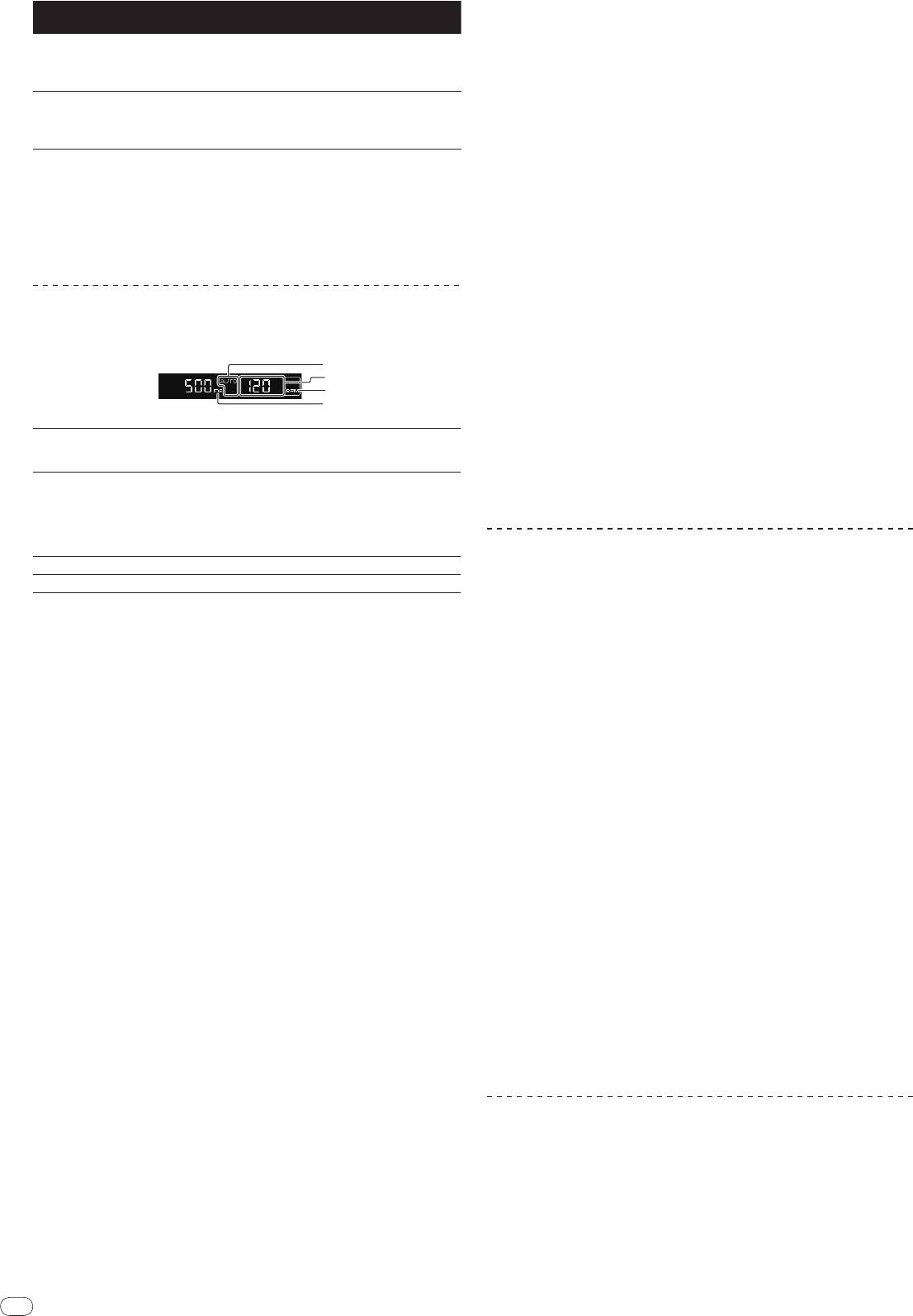
[AUTO] lights when the BPM measurement mode is set to
4 Press [ON/
OFF].
1
AUTO (TAP)
the auto mode.
The sound that has passed through the external effector is output.
[TAP] lights when in the manual input mode.
! The effect turns off when [ON/
OFF] is pressed again.
When in the auto mode, this displays the automatically
! If the [SEND/RETURN] terminal connection is canceled when [RETURN] is on,
detected BPM value.
[ON/
OFF] turns off and [DELAY] is selected at [EFFECT SELECT].
BPM value display (3
When the BPM cannot be detected, the previously detected
2
digits)
BPM value is displayed and flashes.
When in the manual input mode, this displays the BPM
value that was input manually.
Using the MIDI function
3
BPM
This is always lit.
4
% (ms)
These light according to the units for the different effects.
Operating the DJ software
The DJM-2000 also outputs the operating data for the buttons and dials in MIDI
1 Press [AUTO/TAP].
format. If you connect a computer with a built-in MIDI-compatible DJ software
Select the BPM measurement mode.
via a USB cable, you can operate the DJ software on this unit.
— AUTO: The BPM is automatically measured from the input audio signal.
Install the DJ software on your computer in advance. Also, adjust audio and MIDI
AUTO is set when this unit’s power is turned on.
settings for the DJ software.
— TAP: The BPM is input manually by tapping [TAP].
! For MIDI channel setting instructions, see Changing the settings on page 24.
! The BPM measurement range when AUTO is selected is 70 to 180. Depending
on the track, it may not be possible to properly measure the BPM. If not, the
1 Connect this unit’s [USB] terminal to the computer.
BPM value flashes on the display. In this case, use the [TAP] button to input
For details about connections, see Connecting a computer on page 8.
the BPM manually.
2 Start the DJ software.
2 Press one of the [CH SELECT] buttons.
This selects the channel to which the effect is applied.
3 Press [ON/
OFF] in the [MIDI] section.
— [1] – [4]: The effect is applied to the sounds of channels [CH1] – [CH4].
Turn the MIDI function on.
— [MIC]: The effect is applied to the sound of the [MIC] channel.
Transmission of the MIDI messages begin.
— [A], [B]: The effect is applied to the sound of the crossfader’s [A] (left) or
! When the faders and controls are moved, messages are sent according to the
[B] (right) side.
positions of the faders and controls. For messages output by this unit, see
— [M]: The effect is applied to the sound of the [MASTER] channel.
List of MIDI Messages on page 18.
! MIDI messages for the positions of all the buttons, faders and controls can
3 Press one of the [EFFECT SELECT] buttons.
be sent in a single batch by pressing the [START/
STOP] button for at least 2
This selects the type of effect.
seconds (Snapshot function).
! For the types of effects, see Types of BEAT EFFECT on page 22.
! The MIDI timing clock (BPM information) is sent regardless of [ON/
OFF].
! When [SEND/RETURN] is selected, see Using the external effector below.
! When [ON/
OFF] in the [MIDI] section is pressed again, sending of MIDI mes-
sages stops.
4 Press one of the beat buttons.
This selects the beat fraction for synchronizing the effect sound.
The effect time corresponding to the beat fraction is set automatically.
Sending the MIDI start and MIDI stop messages
! The beat fraction can be changed by turning [TIME] while pressing the beat
button.
Press [START/
STOP] in the [MIDI] section.
! The MIDI start and MIDI stop messages are sent alternately each time the
5 Press [ON/
OFF].
[START/
STOP] button is pressed, regardless of whether the MIDI function is
The effect is applied to the sound.
on or off.
The effect’s time parameter can be adjusted by turning the [TIME] control.
The effect’s quantity parameter can be adjusted by turning the [LEVEL/
DEPTH]
control.
[ON/
OFF] flashes when the effect is turned on.
Using the MIDI control screens
! The effect turns off when [ON/
OFF] is pressed again.
This unit is equipped with four types of MIDI control screens. Use them accord-
ing to your DJ software.
Inputting the BPM manually
1 Press the [MIDI] button to the right of the touch panel.
The [MIDI CONTROL] screen appears on the touch panel.
Tap the [TAP] button at least two times with a finger in (quarter
note) beat with the currently playing sound.
2 Select a type, from [TYPE A] to [TYPE D].
The average value of the intervals at which the [TAP] button was tapped is set as
This selects the type of MIDI control screen.
the BPM.
! When [PAGE1] or [PAGE2] is pressed, the page being displayed switches.
! When the BPM is set using the [TAP] button, the beat fraction is set to 1/1,
and the time of one beat (one quarter note) is set as the effect time.

3 Operate the touch panel buttons or faders.
Transmission of the MIDI messages begin.
For messages output by this unit, see List of MIDI Messages on page 18.
English
Operating an external MIDI sequencer
This unit sends the tempo of the currently playing source (BPM information)
as the MIDI timing clock. This can be used to synchronize an external MIDI
sequencer with the tempo of the source.
! External MIDI sequencers not supporting MIDI timing clocks cannot be
synchronized.
! External MIDI sequencers cannot be synchronized for sources for which the
BPM cannot be measured stably.
! MIDI timing clocks are output even for BPM values input manually by tapping
the [TAP] button with a finger. The MIDI timing clock output range is 40 BPM
to 250 BPM.
1 Connect the [MIDI OUT] terminal to the external MIDI
sequencer’s MIDI IN terminal using a commercially available MIDI
cable.
2 Set the external MIDI sequencer’s sync mode to Slave.
3 Press [START/
STOP].
The MIDI start message is sent.
4 Press [ON/
OFF] in the [MIDI] section.
Transmission of the MIDI messages begin.
En
17
DRB1497-B
1716
18
En
DRB1497-B
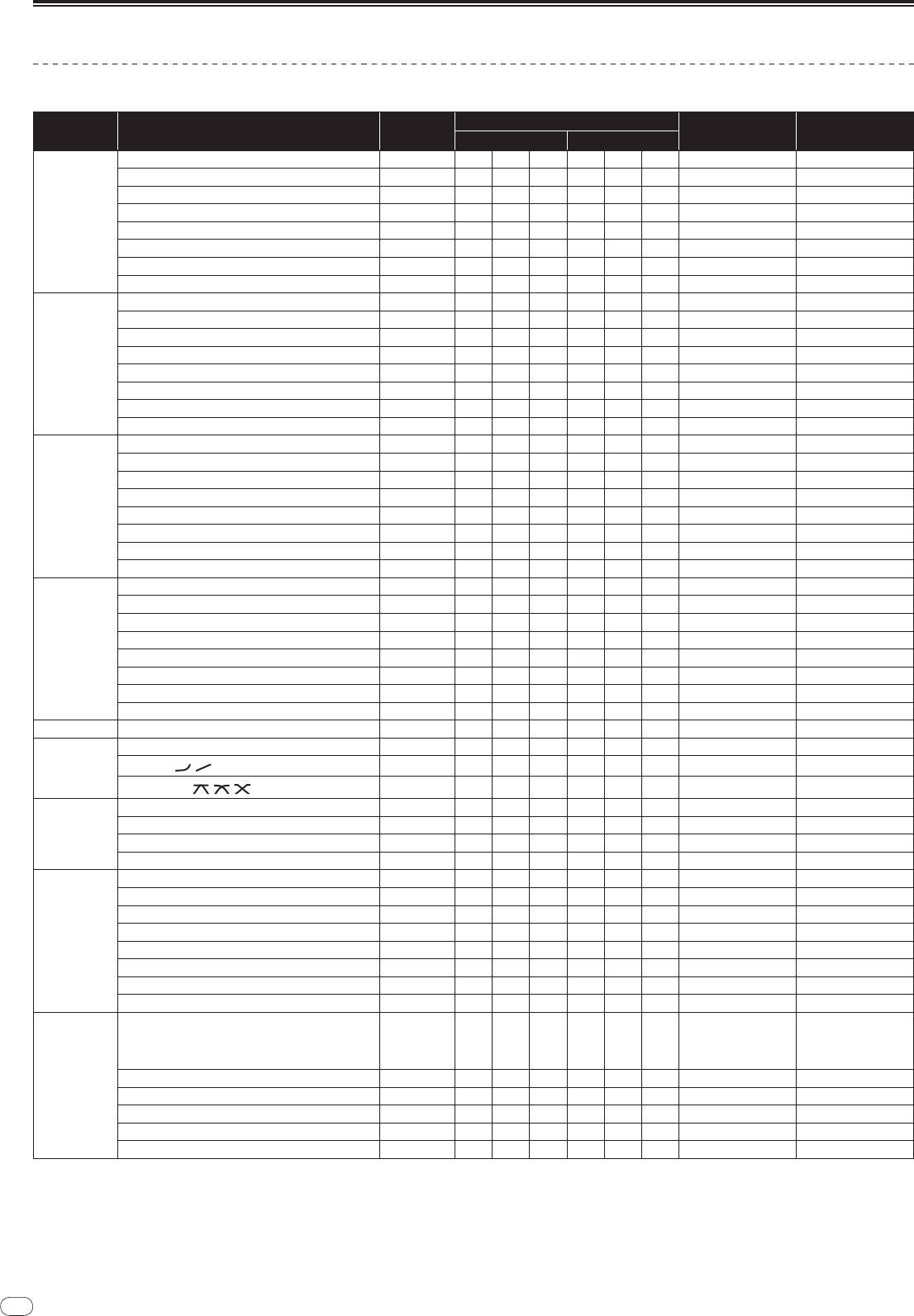
List of MIDI Messages
Control Panel
MIDI Messages
Category SW Name SW Type
Trigger/
Toggle Notes
MSB LSB
TRIM
VR Bn 01 dd — — — — 0-127
HI
VR Bn 02 dd — — — — 0-127
MID
VR Bn 03 dd — — — — 0-127
LOW
VR Bn 04 dd — — — — 0-127
CH1
FILTER
VR Bn 05 dd — — — — 0-127
Channel fader VR Bn 11 dd — — — — 0-127
CROSS FADER ASSIGN
SW Bn 41 dd — — — — 0, 64, 127
CUE
BTN Bn 46 dd — — — Trigger/
Toggle OFF=0, ON=127
TRIM
VR Bn 06 dd — — — — 0-127
HI
VR Bn 07 dd — — — — 0-127
MID
VR Bn 08 dd — — — — 0-127
LOW
VR Bn 09 dd — — — — 0-127
CH2
FILTER
VR Bn 0A dd — — — — 0-127
Channel fader VR Bn 12 dd — — — — 0-127
CROSS FADER ASSIGN
SW Bn 42 dd — — — — 0, 64, 127
CUE
BTN Bn 47 dd — — — Trigger/
Toggle OFF=0, ON=127
TRIM
VR Bn 0C dd — — — — 0-127
HI
VR Bn 0E dd — — — — 0-127
MID
VR Bn 0F dd — — — — 0-127
LOW
VR Bn 15 dd — — — — 0-127
CH 3
FILTER
VR Bn 16 dd — — — — 0-127
Channel fader VR Bn 13 dd — — — — 0-127
CROSS FADER ASSIGN
SW Bn 43 dd — — — — 0, 64, 127
CUE
BTN Bn 48 dd — — — Trigger/
Toggle OFF=0, ON=127
TRIM
VR Bn 50 dd — — — — 0-127
HI
VR Bn 51 dd — — — — 0-127
MID
VR Bn 5C dd — — — — 0-127
LOW
VR Bn 52 dd — — — — 0-127
CH4
FILTER
VR Bn 53 dd — — — — 0-127
Channel fader VR Bn 14 dd — — — — 0-127
CROSS FADER ASSIGN
SW Bn 44 dd — — — — 0, 64, 127
CUE
BTN Bn 49 dd — — — Trigger/
Toggle OFF=0, ON=127
Crossfader Crossfader VR Bn 0B dd — — — — 0-127
CH EQ (ISOLATOR, EQ) SW Bn 21 dd — — — — 0, 127
CURVE SETTING
CH FADER (
,
)
SW Bn 5E dd — — — — 0, 127
CROSS FADER (
, ,
)
SW Bn 5F dd — — — — 0, 64, 127
BALANCE
VR Bn 17 dd — — — — 0-127
MASTER level VR Bn 18 dd — — — — 0-127
MASTER
CUE
BTN Bn 4A dd — — — Trigger/
Toggle OFF=0, ON=127
BOOTH MONITOR
VR Bn 19 dd — — — — 0-127
1
1
BTN Bn 22 dd — — — Trigger/
Toggle
OFF=0, ON=127
1
2
BTN Bn 23 dd — — — Trigger/
Toggle
OFF=0, ON=127
1
3
BTN Bn 24 dd — — — Trigger/
Toggle
OFF=0, ON=127
1
4
BTN Bn 25 dd — — — Trigger/
Toggle
OFF=0, ON=127
CH SELECT
1
MIC
BTN Bn 26 dd — — — Trigger/
Toggle
OFF=0, ON=127
1
A
BTN Bn 27 dd — — — Trigger/
Toggle
OFF=0, ON=127
1
B
BTN Bn 28 dd — — — Trigger/
Toggle
OFF=0, ON=127
1
M
BTN Bn 29 dd — — — Trigger/
Toggle
OFF=0, ON=127
TIME value (half the
value when FILTER or
TIME
VR Bn 0D MSB Bn 2D LSB —
PHASER is selected for
EFFECT SELECT)
ON/
OFF BTN Bn 40 dd — — — Trigger/
Toggle OFF=0, ON=127
BEAT EFFECT
AUTO/
TAP
BTN Bn 45 dd — — — Trigger/
Toggle OFF=0, ON=127
CUE
BTN Bn 4B dd — — — Trigger/
Toggle OFF=0, ON=127
TAP
BTN Bn 4E dd — — — Trigger/
Trigger OFF=0, ON=127
LEVEL/
DEPTH VR Bn 5B dd — — — — 0-127
18
MIDI Messages
Category SW Name SW Type
Trigger/
Toggle Notes
MSB LSB
1
English
DELAY
BTN Bn 2A dd — — — Trigger/
Toggle
OFF=0, ON=127
1
MULTI TAP DELAY
BTN Bn 2B dd — — — Trigger/
Toggle
OFF=0, ON=127
1
ROLL
BTN Bn 2E dd — — — Trigger/
Toggle
OFF=0, ON=127
1
REV ROLL
BTN Bn 2F dd — — — Trigger/
Toggle
OFF=0, ON=127
1
TRANS
BTN Bn 35 dd — — — Trigger/
Toggle
OFF=0, ON=127
1
GATE
BTN Bn 3D dd — — — Trigger/
Toggle
OFF=0, ON=127
EFFECT SELECT
1
ECHO
BTN Bn 37 dd — — — Trigger/
Toggle
OFF=0, ON=127
1
REVERB
BTN Bn 36 dd — — — Trigger/
Toggle
OFF=0, ON=127
1
SLIP ROLL
BTN Bn 3A dd — — — Trigger/
Toggle
OFF=0, ON=127
1
FILTER
BTN Bn 3B dd — — — Trigger/
Toggle
OFF=0, ON=127
1
PHASER
BTN Bn 39 dd — — — Trigger/
Toggle
OFF=0, ON=127
1
SEND/
RETURN
BTN Bn 3E dd — — — Trigger/
Toggle
OFF=0, ON=127
HI
VR Bn 66 dd — — — — 0-127
EFFECT FRE-
MID
VR Bn 67 dd — — — — 0-127
QUENCY
LOW
VR Bn 68 dd — — — — 0-127
1
NOISE
BTN Bn 55 dd — — — Trigger/
Toggle
OFF=0, ON=127
1
ZIP
BTN Bn 56 dd — — — Trigger/
Toggle
OFF=0, ON=127
1
CRUSH
BTN Bn 57 dd — — — Trigger/
Toggle
OFF=0, ON=127
1
INST FX
JET
BTN Bn 69 dd — — — Trigger/
Toggle
OFF=0, ON=127
1
HPF
BTN Bn 6A dd — — — Trigger/
Toggle
OFF=0, ON=127
1
LPF
BTN Bn 6B dd — — — Trigger/
Toggle
OFF=0, ON=127
PARAMETER
VR Bn 6C dd — — — — 0-127
HI
VR Bn 1E dd — — — — 0-127
MIC
LOW
VR Bn 1F dd — — — — 0-127
LEVEL
VR Bn 1A dd — — — — 0-127
HEADPHONES
MIXING
VR Bn 1B dd — — — — 0-127
LINK CUE
BTN Bn 73 dd — — — Trigger/
Toggle OFF=0, ON=127
CUE
BTN Bn 6E dd — — — Trigger/
Toggle OFF=0, ON=127
MIDI
BTN Bn 6F dd — — — Trigger/
Toggle OFF=0, ON=127
Touch panel
1
MIX
BTN Bn 70 dd — — — Trigger/
Toggle
OFF=0, ON=127
control
1
REMIX
BTN Bn 71 dd — — — Trigger/
Toggle
OFF=0, ON=127
ON/
OFF BTN Bn 72 dd — — — Trigger/
Toggle OFF=0, ON=127
START
BTN FA — — — — — — —
MIDI
STOP
BTN FC — — — — — — —
1 When turning one button on switches another button from on to off, MIDI on and off messages are sent from the two buttons.
When there is no button that switches off, only the MIDI on message is sent from the button that was pressed.
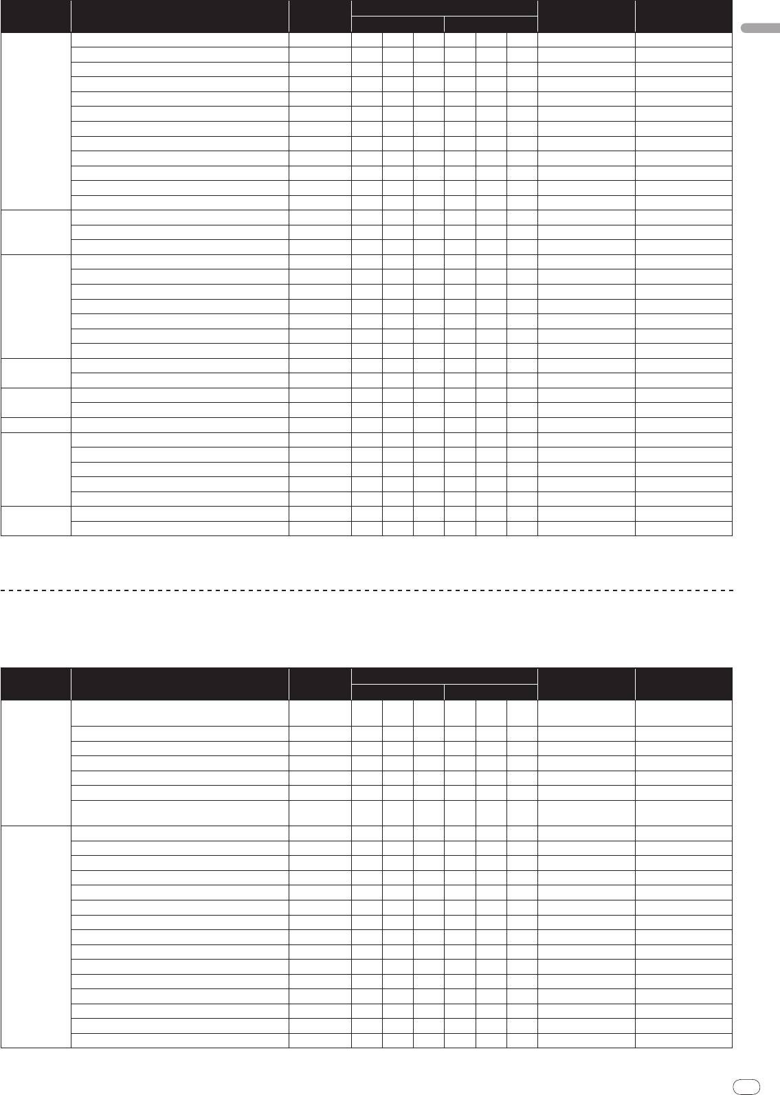
Touch panel
FREQUENCY MIX, SIDECHAIN REMIX
MIDI Messages
Category SW Name SW Type
Trigger/
Toggle Notes
MSB LSB
0 - 127 (very top of
Touch fader 1 VR Bn 38 dd — — — —
screen)
Touch fader 2 VR Bn 4C dd — — — — 0-127
Touch fader 3 VR Bn 4D dd — — — — 0-127
FREQUENCY MIX
Touch fader 4 VR Bn 74 dd — — — — 0-127
Touch fader 5 VR Bn 75 dd — — — — 0-127
Touch fader 6 VR Bn 76 dd — — — — 0-127
0 - 127 (very bottom of
Touch fader 7 VR Bn 77 dd — — — —
screen)
X axis of control area VR Bn 1C dd — — — — 0-127
Y axis of control area VR Bn 3C dd — — — — 0-127
LEVEL/
DEPTH VR Bn 31 dd — — — — 0-127
CH1
BTN 9n 49 dd — — — Trigger/
Toggle OFF=0, ON=127
CH2
BTN 9n 4A dd — — — Trigger/
Toggle OFF=0, ON=127
CH3
BTN 9n 4B dd — — — Trigger/
Toggle OFF=0, ON=127
CH4
BTN 9n 4C dd — — — Trigger/
Toggle OFF=0, ON=127
SIDECHAIN
TRIGGER CH (SAMPLING/
TRIGGER CH) SAME BTN 9n 51 dd — — — Trigger/
Toggle OFF=0, ON=127
REMIX
TRIGGER CH (SAMPLING/
TRIGGER CH) CH1 BTN 9n 52 dd — — — Trigger/
Toggle OFF=0, ON=127
TRIGGER CH (SAMPLING/
TRIGGER CH) CH2 BTN 9n 53 dd — — — Trigger/
Toggle OFF=0, ON=127
TRIGGER CH (SAMPLING/
TRIGGER CH) CH3 BTN 9n 54 dd — — — Trigger/
Toggle OFF=0, ON=127
TRIGGER CH (SAMPLING/
TRIGGER CH) CH4 BTN 9n 55 dd — — — Trigger/
Toggle OFF=0, ON=127
TRIGGER BAND LOW BTN 9n 59 dd — — — Trigger/
Toggle OFF=0, ON=127
TRIGGER BAND MID BTN 9n 5A dd — — — Trigger/
Toggle OFF=0, ON=127
TRIGGER BAND HI BTN 9n 5B dd — — — Trigger/
Toggle OFF=0, ON=127
En
19
DRB1497-B
1918
20
En
DRB1497-B
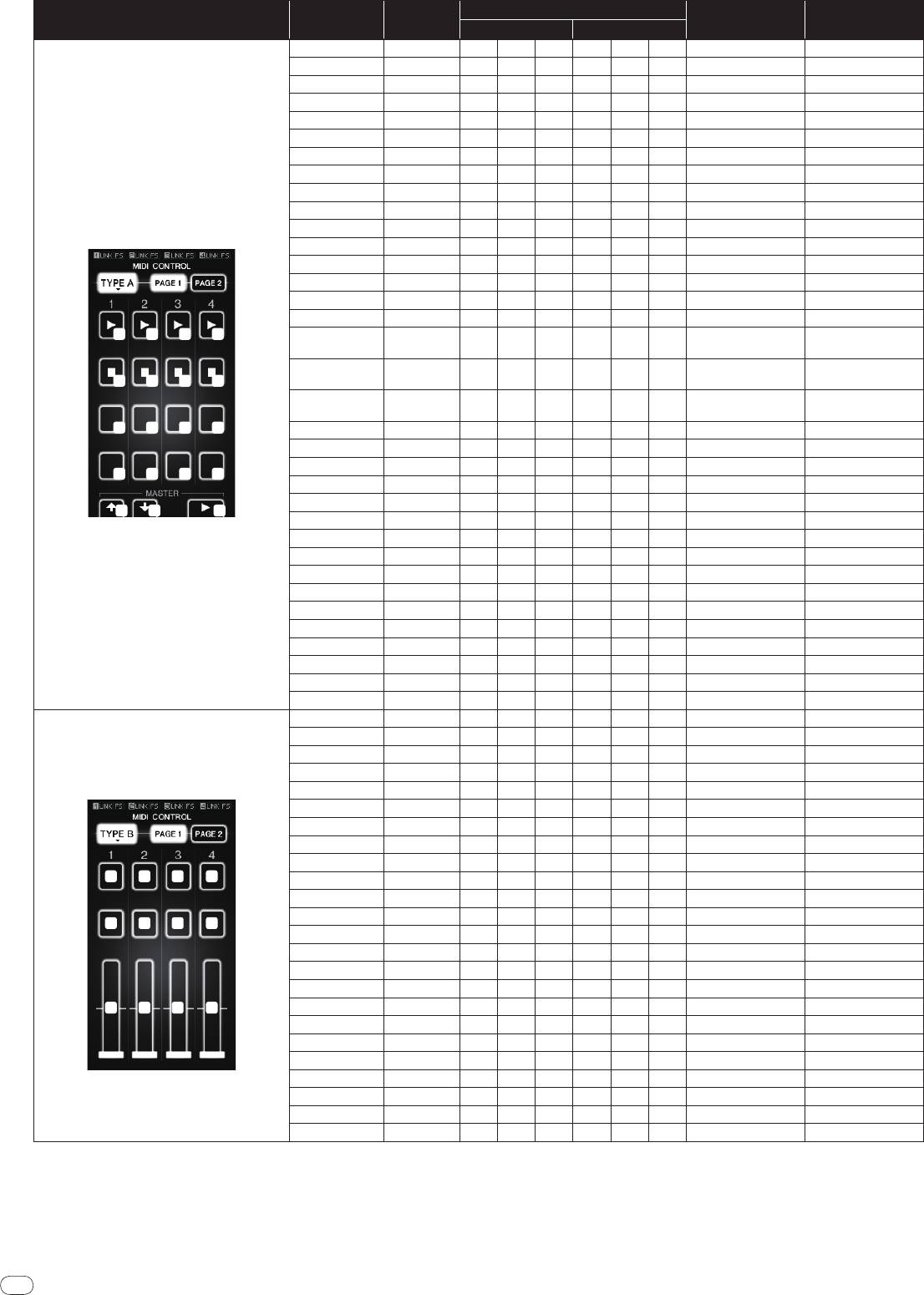
MIDI CONTROL
Switch
MIDI Messages
Category
SW Type
Trigger/
Toggle Notes
position
MSB LSB
TYPE A
20
1 2 3 4
5 6 7 8
9
10 11 12
13 14 15 16
17 18 19
[PAGE1]–9 BTN 9n 5D dd — — — Trigger/
Toggle OFF=0, ON=127
[PAGE1]–10 BTN 9n 5E dd — — — Trigger/
Toggle OFF=0, ON=127
[PAGE1]–11 BTN 9n 5F dd — — — Trigger/
Toggle OFF=0, ON=127
[PAGE1]–12 BTN 9n 60 dd — — — Trigger/
Toggle OFF=0, ON=127
[PAGE1]–13 BTN 9n 61 dd — — — Trigger/
Toggle OFF=0, ON=127
[PAGE1]–14 BTN 9n 62 dd — — — Trigger/
Toggle OFF=0, ON=127
[PAGE1]–15 BTN 9n 63 dd — — — Trigger/
Toggle OFF=0, ON=127
[PAGE1]–16 BTN 9n 64 dd — — — Trigger/
Toggle OFF=0, ON=127
[PAGE1]–5 BTN 9n 65 dd — — — Trigger/
Toggle OFF=0, ON=127
[PAGE1]–6 BTN 9n 66 dd — — — Trigger/
Toggle OFF=0, ON=127
[PAGE1]–7 BTN 9n 67 dd — — — Trigger/
Toggle OFF=0, ON=127
[PAGE1]–8 BTN 9n 68 dd — — — Trigger/
Toggle OFF=0, ON=127
[PAGE1]–1 BTN 9n 69 dd — — — Trigger/
Toggle OFF=0, ON=127
[PAGE1]–2 BTN 9n 6A dd — — — Trigger/
Toggle OFF=0, ON=127
[PAGE1]–3 BTN 9n 6B dd — — — Trigger/
Toggle OFF=0, ON=127
[PAGE1]–4 BTN 9n 6C dd — — — Trigger/
Toggle OFF=0, ON=127
[PAGE1],
BTN 9n 7D dd — — — Trigger/
Toggle OFF=0, ON=127
[PAGE2]–17
[PAGE1],
BTN 9n 7E dd — — — Trigger/
Toggle OFF=0, ON=127
[PAGE2]–18
[PAGE1],
BTN 9n 7F dd — — — Trigger/
Toggle OFF=0, ON=127
[PAGE2]–19
[PAGE2]–9 BTN 9n 6D dd — — — Trigger/
Toggle OFF=0, ON=127
[PAGE2]–10 BTN 9n 6E dd — — — Trigger/
Toggle OFF=0, ON=127
[PAGE2]–11 BTN 9n 6F dd — — — Trigger/
Toggle OFF=0, ON=127
[PAGE2]–12 BTN 9n 70 dd — — — Trigger/
Toggle OFF=0, ON=127
[PAGE2]–13 BTN 9n 71 dd — — — Trigger/
Toggle OFF=0, ON=127
[PAGE2]–14 BTN 9n 72 dd — — — Trigger/
Toggle OFF=0, ON=127
[PAGE2]–15 BTN 9n 73 dd — — — Trigger/
Toggle OFF=0, ON=127
[PAGE2]–16 BTN 9n 74 dd — — — Trigger/
Toggle OFF=0, ON=127
[PAGE2]–5 BTN 9n 75 dd — — — Trigger/
Toggle OFF=0, ON=127
[PAGE2]–6 BTN 9n 76 dd — — — Trigger/
Toggle OFF=0, ON=127
[PAGE2]–7 BTN 9n 77 dd — — — Trigger/
Toggle OFF=0, ON=127
[PAGE2]–8 BTN 9n 78 dd — — — Trigger/
Toggle OFF=0, ON=127
[PAGE2]–1 BTN 9n 79 dd — — — Trigger/
Toggle OFF=0, ON=127
[PAGE2]–2 BTN 9n 7A dd — — — Trigger/
Toggle OFF=0, ON=127
[PAGE2]–3 BTN 9n 7B dd — — — Trigger/
Toggle OFF=0, ON=127
[PAGE2]–4 BTN 9n 7C dd — — — Trigger/
Toggle OFF=0, ON=127
TYPE B
1 2 3 4
5 6 7 8
9
10 11 12
[PAGE1]–9 VR Bn 01 dd — — — — 0-127
[PAGE1]–10 VR Bn 02 dd — — — — 0-127
[PAGE1]–11 VR Bn 03 dd — — — — 0-127
[PAGE1]–12 VR Bn 04 dd — — — — 0-127
[PAGE2]–9 VR Bn 05 dd — — — — 0-127
[PAGE2]–10 VR Bn 06 dd — — — — 0-127
[PAGE2]–11 VR Bn 07 dd — — — — 0-127
[PAGE2]–12 VR Bn 08 dd — — — — 0-127
[PAGE1]–1 BTN 9n 30 dd — — — Trigger/
Toggle OFF=0, ON=127
[PAGE1]–2 BTN 9n 31 dd — — — Trigger/
Toggle OFF=0, ON=127
[PAGE1]–3 BTN 9n 32 dd — — — Trigger/
Toggle OFF=0, ON=127
[PAGE1]–4 BTN 9n 33 dd — — — Trigger/
Toggle OFF=0, ON=127
[PAGE1]–5 BTN 9n 34 dd — — — Trigger/
Toggle OFF=0, ON=127
[PAGE1]–6 BTN 9n 35 dd — — — Trigger/
Toggle OFF=0, ON=127
[PAGE1]–7 BTN 9n 36 dd — — — Trigger/
Toggle OFF=0, ON=127
[PAGE1]–8 BTN 9n 37 dd — — — Trigger/
Toggle OFF=0, ON=127
[PAGE2]–1 BTN 9n 38 dd — — — Trigger/
Toggle OFF=0, ON=127
[PAGE2]–2 BTN 9n 39 dd — — — Trigger/
Toggle OFF=0, ON=127
[PAGE2]–3 BTN 9n 3A dd — — — Trigger/
Toggle OFF=0, ON=127
[PAGE2]–4 BTN 9n 3B dd — — — Trigger/
Toggle OFF=0, ON=127
[PAGE2]–5 BTN 9n 48 dd — — — Trigger/
Toggle OFF=0, ON=127
[PAGE2]–6 BTN 9n 49 dd — — — Trigger/
Toggle OFF=0, ON=127
[PAGE2]–7 BTN 9n 4A dd — — — Trigger/
Toggle OFF=0, ON=127
[PAGE2]–8 BTN 9n 4B dd — — — Trigger/
Toggle OFF=0, ON=127
Switch
MIDI Messages
Category
SW Type
Trigger/
Toggle Notes
position
MSB LSB
English
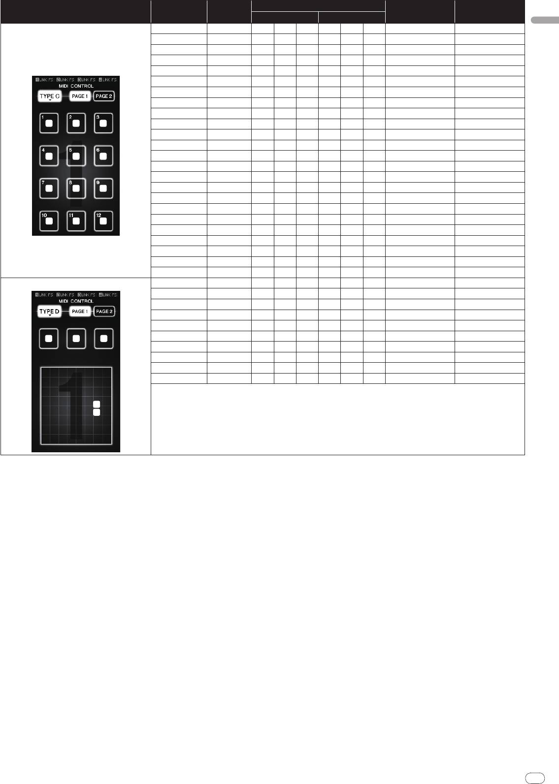
TYPE C
En
21
DRB1497-B
2120
1 2 3
4 5 6
7 8 9
10 11 12
[PAGE1]–1 BTN 9n 3C dd — — — Trigger/
Toggle OFF=0, ON=127
[PAGE1]–2 BTN 9n 3D dd — — — Trigger/
Toggle OFF=0, ON=127
[PAGE1]–3 BTN 9n 3E dd — — — Trigger/
Toggle OFF=0, ON=127
[PAGE1]–4 BTN 9n 3F dd — — — Trigger/
Toggle OFF=0, ON=127
[PAGE1]–5 BTN 9n 40 dd — — — Trigger/
Toggle OFF=0, ON=127
[PAGE1]–6 BTN 9n 41 dd — — — Trigger/
Toggle OFF=0, ON=127
[PAGE1]–7 BTN 9n 42 dd — — — Trigger/
Toggle OFF=0, ON=127
[PAGE1]–8 BTN 9n 43 dd — — — Trigger/
Toggle OFF=0, ON=127
[PAGE1]–9 BTN 9n 44 dd — — — Trigger/
Toggle OFF=0, ON=127
[PAGE1]–10 BTN 9n 45 dd — — — Trigger/
Toggle OFF=0, ON=127
[PAGE1]–11 BTN 9n 46 dd — — — Trigger/
Toggle OFF=0, ON=127
[PAGE1]–12 BTN 9n 47 dd — — — Trigger/
Toggle OFF=0, ON=127
[PAGE2]–1 BTN 9n 24 dd — — — Trigger/
Toggle OFF=0, ON=127
[PAGE2]–2 BTN 9n 25 dd — — — Trigger/
Toggle OFF=0, ON=127
[PAGE2]–3 BTN 9n 26 dd — — — Trigger/
Toggle OFF=0, ON=127
[PAGE2]–4 BTN 9n 27 dd — — — Trigger/
Toggle OFF=0, ON=127
[PAGE2]–5 BTN 9n 28 dd — — — Trigger/
Toggle OFF=0, ON=127
[PAGE2]–6 BTN 9n 29 dd — — — Trigger/
Toggle OFF=0, ON=127
[PAGE2]–7 BTN 9n 2A dd — — — Trigger/
Toggle OFF=0, ON=127
[PAGE2]–8 BTN 9n 2B dd — — — Trigger/
Toggle OFF=0, ON=127
[PAGE2]–9 BTN 9n 2C dd — — — Trigger/
Toggle OFF=0, ON=127
[PAGE2]–10 BTN 9n 2D dd — — — Trigger/
Toggle OFF=0, ON=127
[PAGE2]–11 BTN 9n 2E dd — — — Trigger/
Toggle OFF=0, ON=127
[PAGE2]–12 BTN 9n 2F dd — — — Trigger/
Toggle OFF=0, ON=127
TYPE D
1 2 3
4
5
[PAGE1]–1 BTN 9n 57 dd — — — Trigger/
Toggle OFF=0, ON=127
[PAGE1]–2 BTN 9n 58 dd — — — Trigger/
Toggle OFF=0, ON=127
[PAGE1]–3 BTN 9n 59 dd — — — Trigger/
Toggle OFF=0, ON=127
[PAGE1]–4 VR Bn 1C dd — — — — 0-127
[PAGE1]–5 VR Bn 3C dd — — — — 0-127
[PAGE2]–1 BTN 9n 5A dd — — — Trigger/
Toggle OFF=0, ON=127
[PAGE2]–2 BTN 9n 5B dd — — — Trigger/
Toggle OFF=0, ON=127
[PAGE2]–3 BTN 9n 5C dd — — — Trigger/
Toggle OFF=0, ON=127
[PAGE2]–4 VR Bn 31 dd — — — — 0-127
[PAGE2]–5 VR Bn 32 dd — — — — 0-127
22
En
DRB1497-B
Types of BEAT EFFECT
1
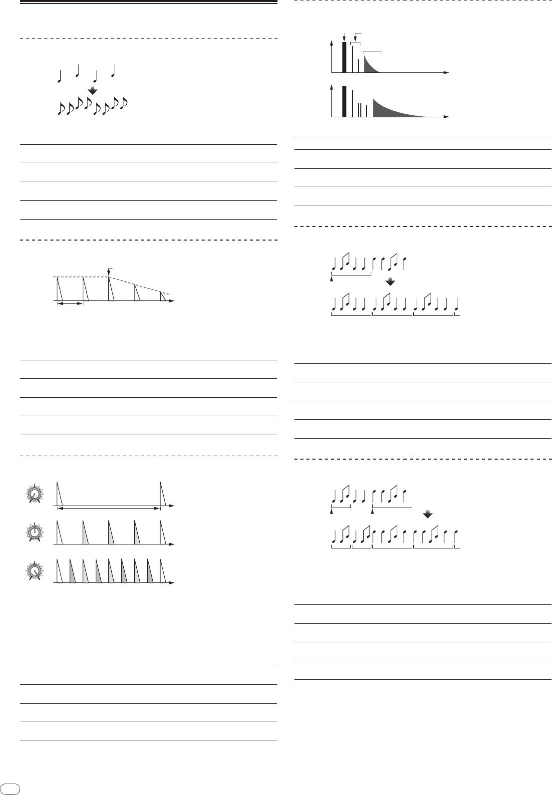
DELAY
22
Original
(4 beats)
1/2 delay
(8 beats)
This function outputs a delay sound once according to the beat button’s fraction.
When 1/2 beat delay sound is added, 4 beats become 8 beats.
Use these to set the delay time from 1/8 to 4/1 with respect to 1
Beat buttons (parameter 1)
beat of BPM time.
Use this to set the delay time.
TIME (parameter 2)
1 to 4000 (ms)
LEVEL/
DEPTH (param-
Use this to set the balance between the original sound and the
eter 3)
delay sound.
EFFECT FREQUENCY
Use these to set the balance between the original sound and
(parameter 4)
the delay sound for the different bands.
1
2
ECHO
Input sound turned off
Fade-out
Time
1 beat
This function outputs increasingly attenuated delay sounds several times accord-
ing to the beat button’s fraction.
With 1/1 beat echoes, the delay sounds are faded out according to the track’s
tempo even after the input sound has been cut.
Use these to set the delay time from 1/8 to 4/1 with respect to 1
Beat buttons (parameter 1)
beat of BPM time.
Use this to set the delay time.
TIME (parameter 2)
1 to 4000 (ms)
LEVEL/
DEPTH (param-
Use this to set the balance between the original sound and the
eter 3)
echo sound.
EFFECT FREQUENCY
Use these to set the balance between the original sound and
(parameter 4)
the echo for the different bands.
1
MULTI TAP DELAY
MIN MAX
1/1 beat
Time
MIN MAX
1/4 beat
MIN MAX
EFFECT FREQUENCY
1/8 beat
1
2
REVERB
This function outputs up to 7 delay sounds in 1/8 units, according to the beat
button’s fraction.
The volume of the delay sound can be adjusted with the [EFFECT FREQUENCY]
controls.
The volume of the odd delay sounds is adjusted from [MIN] to the center posi-
tion, the volume of the even delay sounds is adjusted from the center position to
[MAX].
The effect time is set from 1/8 to 4/1 with respect to 1 beat of
Beat buttons (parameter 1)
BPM time.
Use this to set the delay time.
TIME (parameter 2)
10 to 4000 (ms)
LEVEL/
DEPTH (param-
Use this to set the balance between the original sound and the
eter 3)
delay sound.
EFFECT FREQUENCY
This sets the volume of the delay sound for the different bands.
(parameter 4)
Direct sound
Early reflected sound
Level
Reverberations
1%
Time
100%
This function adds a reverberation effect to the input sound.
Beat buttons (parameter 1) These set the degree of the reverb effect from 1 to 100 %.
Use this to set the degree of the reverb effect.
TIME (parameter 2)
1 to 100 (%)
LEVEL/
DEPTH (param-
Sets the balance between the original sound and the effect
eter 3)
sound.
EFFECT FREQUENCY
Use these to set the balance between the original sound and
(parameter 4)
the effect sound for the different bands.
1
2
ROLL
Original
Effect turned on
1/1 roll
Repeated
This function records the input sound at the point at which the [ON/
OFF] but-
ton is pressed and repeats the recorded sound according to the beat button’s
fraction.
The effect time is set from 1/8 to 4/1 with respect to 1 beat of
Beat buttons (parameter 1)
BPM time.
Use this to set the effect time.
TIME (parameter 2)
10 to 4000 (ms)
LEVEL/
DEPTH (param-
Use this to set the balance between the original sound and
eter 3)
ROLL.
EFFECT FREQUENCY
Use these to set the balance between the original sound and
(parameter 4)
the ROLL for the different bands.
1
2
SLIP ROLL
Original
Effect turned on
Changed from 1/2
to 1/1
Roll
1/1 repeat1/2 repeat
This function records the input sound at the point at which the [ON/
OFF] but-
ton is pressed and repeats the recorded sound according to the beat button’s
fraction.
When the effect time changes, the input sound is recorded again.
The effect time is set from 1/8 to 4/1 with respect to 1 beat of
Beat buttons (parameter 1)
BPM time.
Use this to set the effect time.
TIME (parameter 2)
10 to 4000 (ms)
LEVEL/
DEPTH (param-
Use this to set the balance between the original sound and
eter 3)
ROLL.
EFFECT FREQUENCY
Use these to set the balance between the original sound and
(parameter 4)
the ROLL for the different bands.
1
2
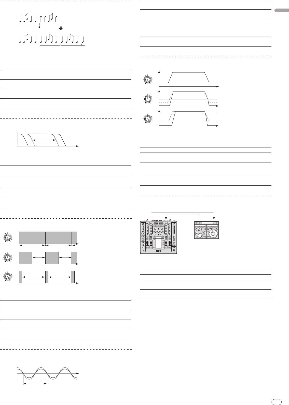
REV ROLL
English
En
23
DRB1497-B
2322
Original
Effect turned on
1/1 reverse
roll
Reversed and repeated
This function records the input sound at the point at which the [ON/
OFF] but-
ton is pressed, reverses the recorded sound and repeats it according to the beat
button’s fraction.
The effect time is set from 1/8 to 4/1 with respect to 1 beat of
Beat buttons (parameter 1)
BPM time.
Use this to set the effect time.
TIME (parameter 2)
10 to 4000 (ms)
LEVEL/
DEPTH (param-
Use this to set the balance between the original sound and
eter 3)
ROLL.
EFFECT FREQUENCY
Use these to set the balance between the original sound and
(parameter 4)
the ROLL for the different bands.
1
FILTER
Frequency
This function changes the filter’s cut-off frequency according to the beat button’s
fraction.
These set the cycle for moving the cut-off frequency from 1/8 to
Beat buttons (parameter 1)
4/1 with respect to 1 beat of BPM time.
Use this to set the cycle at which the cut-off frequency is
TIME (parameter 2)
moved.
10 to 32000 (ms)
LEVEL/
DEPTH (param-
The further the control is turned clockwise, the more the effect
eter 3)
is stressed.
EFFECT FREQUENCY
These set the balance between the original sound and the
(parameter 4)
effect sound for the different bands.
1
TRANS
MIN MAX
1/1 beat
Time
Cut
Cut
MIN MAX
Cut Cut
MIN MAX
EFFECT FREQUENCY
This function cuts the sound according to the beat button’s fraction.
The amount of the sound to be cut can be changed at [EFFECT FREQUENCY].
These set the 1/8 to 4/1 cut time with respect to 1 beat of BPM
Beat buttons (parameter 1)
time.
Use this to set the effect time.
TIME (parameter 2)
10 to 16000 (ms)
LEVEL/
DEPTH (param-
Sets the balance between the original sound and the effect
eter 3)
sound.
EFFECT FREQUENCY
This sets the amount of the original sound to be cut for the
(parameter 4)
different bands.
1
PHASER
Phase shift
Time
Cycle
These set the cycle for moving the phaser effect by 1/8 to 4/1
Beat buttons (parameter 1)
with respect to the time of one BPM beat.
This sets the cycle by which the phaser effect is moved.
TIME (parameter 2)
10 to 32000 (ms)
The further the control is turned clockwise, the more the effect
LEVEL/
DEPTH (param-
is stressed.
eter 3)
When turned all the way counterclockwise, only the original
sound is output.
EFFECT FREQUENCY
Use these to set the balance between the original sound and
(parameter 4)
the effect sound for the different bands.
1
GATE
The phaser effect changes according to the beat button fraction.
Level
Threshold
MIN MAX
Time
Threshold
MIN MAX
Threshold
MIN MAX
EFFECT FREQUENCY
This function outputs the input sound that has a level above the threshold level,
cutting the input sound that has a level below the threshold level.
The threshold level can be changed at [EFFECT FREQUENCY].
Beat buttons (parameter 1) This sets the release time between 1 and 100 %.
This sets the release time.
TIME (parameter 2)
1 to 100 (%)
Sets the threshold level.
LEVEL/
DEPTH (param-
The further the control is turned clockwise, the more the effect
eter 3)
is stressed and the sound is cut.
EFFECT FREQUENCY
Use these to set the threshold levels for the different bands.
(parameter 4)
1
SEND/RETURN
SEND
RETURN
Effector
DJM-2000
Connect an external effector, etc., here.
[EFFECT FREQUENCY] can be used as an isolator.
Beat buttons (parameter 1) —
TIME (parameter 2) —
LEVEL/
DEPTH (param-
This adjusts the sound level input to the [RETURN] terminal.
eter 3)
EFFECT FREQUENCY
This sets the audio output level of the RETURN sound for the
(parameter 4)
different bands.
1 When “A”, “B” or “M” is selected with the [CH SELECT] buttons, the effect sound
cannot be monitored by pressing [CUE] (BEAT EFFECT) unless the sound for
the channel you want to monitor is being output from [MASTER] channel.
2 When BEAT EFFECT is off, the effect sound cannot be monitored by pressing
[CUE] (BEAT EFFECT).
Оглавление
- Contents
- Before start
- Connections
- Operations
- Changing the settings
- Additional information
- Sommaire
- Informations
- Raccordements
- Opérations
- Changement des réglages
- Informations supplémentaires
- Inhalt
- Vor der
- Anschlüsse
- Bedienungen
- Ändern der Einstellungen
- Zusätzliche Informationen
- Indice
- Prima di cominciare
- Collegamenti
- Operazioni
- Modifica delle impostazioni
- Informazioni aggiuntive
- Inhoud
- Alvorens te
- Aansluitingen
- Bediening
- Instellingen aanpassen
- Aanvullende informatie
- Contenido
- Antes de empezar a
- Conexiones
- Operaciones
- Cambio de los ajustes
- Información adicional
- Содержание
- До начала
- Подключения
- Операции
- Изменение настроек
- Дополнительная информация


