Pioneer DJM-2000: Additional information
Additional information: Pioneer DJM-2000
English
Additional information
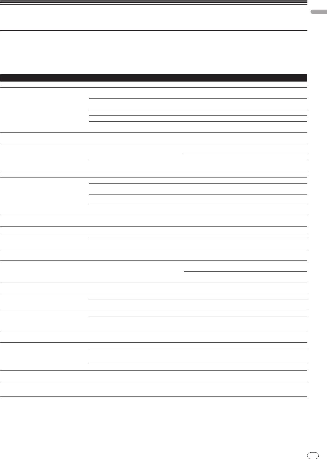
Troubleshooting
! Incorrect operation is often mistaken for trouble or malfunction. If you think that there is something wrong with this component, check the points below. Sometimes
the trouble may lie in another component. Inspect the other components and electrical appliances being used. If the trouble cannot be rectified after checking the
items below, ask your nearest Pioneer authorized service center or your dealer to carry out repair work.
! The player may not operate properly due to static electricity or other external influences. In such cases, normal operation may be restored by unplugging the power
cord then plugging it back in.
Problem Check Remedy
The power is not turned on. Is the power cord properly connected? Plug in the power cord to an AC outlet.
No sound or small sound. Is the [CD/
DIGITAL, PHONO, LINE, USB */
*] switch set to
Switch the [CD/
DIGITAL, PHONO, LINE, USB */
*] switch to the channel’s
the proper position?
input source. (page 12)
Are the [CD, DIGITAL] switches on the rear panel properly
Set the [CD, DIGITAL] switches according to the devices to be played. (page 12)
set?
Are the connection cables properly connected? Connect the connection cables properly. (page 7)
Are the terminals and plugs dirty? Clean the terminals and plugs before making connections.
Is the [MASTER ATT.] switch on the rear panel set to [–6
Switch the [MASTER ATT.] switch. (page 6)
dB], etc.?
Digital sound cannot be output. Is the digital audio output’s sampling frequency (fs) suited
On the [CLUB SETUP] screen, set [DIGITAL SAMPLING RATE] according to
for the specifications of the connected device?
the specifications of the connected equipment. (page 24)
Distorted sound. Is the level of audio output from the microphone channel
Adjust the [MASTER] control so that the master channel level indicator
properly set?
lights at about [0 dB] at the peak level. (page 12)
Set [MASTER ATT.] to [–3 dB] or [–6 dB]. (page 6)
Is the level of audio input to each channel properly set? Adjust the [TRIM] control so that the channel level indicator lights at about
[0 dB] at the peak level. (page 12)
Can’t crossfade. Is the [CROSS FADER ASSIGN] switch properly set? Set the channel’s [CROSS FADER ASSIGN] switch properly. (page 12)
Can’t fader start a DJ player. Is [FADER START] set to off? Set [FADER START] to on at the [USER SETUP] screen. (page 13)
Is the DJ player properly connected to the [CONTROL]
Connect the [CONTROL] terminal and DJ player using a control cord. (page 7)
terminal?
Is the DJ player properly connected to the [LINK] terminal? Connect the DJ player to the [LINK] terminal properly using a LAN cable.
(page 7)
Are the audio cables properly connected? Connect this unit’s audio input terminals and the DJ player’s audio output
terminals by audio cable. (page 7)
BEAT EFFECT function does not work. Are the [CH SELECT] buttons properly set? Press the [CH SELECT] button(s) to select the channel(s) to which you want
to add the effect.
[INST FX] does not work. Is the [FILTER] control set to the proper position? Turn the [FILTER] control clockwise. (page 15)
Can’t use an external effector. Is [ON/
OFF] for the BEAT EFFECT set to on? Press [ON/
OFF] for the BEAT EFFECT to turn [SEND/
RETURN] on. (page 16)
Is the external effector properly connected to the [SEND]
Connect the external effector to the [SEND] and [RETURN] terminals. (page 7)
or [RETURN] terminal?
Distorted sound from an external effector. Is the external effector’s audio output level set to an
Adjust the external effector’s audio output level.
appropriate level?
Tempo (BPM) cannot be measured or measurement
Is the audio input level too high or too low? Adjust the [TRIM] control so that the channel level indicator lights at about
value of tempo (BPM) is implausible.
[0 dB] at the peak level. (page 12)
For some tracks, it may not be possible to measure the tempo (BPM). In this
case, input the tempo manually using the [TAP] button. (page 16)
Measured tempo (BPM) differs from tempo indicated
— The values may differ slightly due to the different ways in which the BPM is
on CD.
measured. There is no need to make any corrections.
MIDI sequencer does not synchronize. Is the MIDI sequencer’s sync mode set to Slave? Set the MIDI sequencer’s sync mode to Slave.
Does the MIDI sequencer you are using support MIDI
MIDI sequencers not supporting MIDI timing clocks cannot be synchro-
timing clocks?
nized.
MIDI control does not work. Is the MIDI channel turned on? Press [ON/
OFF] in the [MIDI] section. (page 16)
Are the MIDI settings properly set? To operate DJ software with this unit, this unit’s MIDI messages must be
assigned to the DJ software you are using. For instructions on assigning
messages, see your DJ software’s operating instructions.
This unit is not recognized after it has been connected
Is the driver software properly installed on your computer? Install the driver software. If the software is already installed, re-install it.
to a computer.
(page 8)
Sound of a computer cannot be output from this unit. Are this unit and computer properly connected? Connect this unit and computer using a USB cable. (page 8)
Are the audio output device settings properly set? Select this unit with the audio output device settings. For instructions
on making settings for your application, see your application’s operating
instructions.
Is this unit’s input selector switch properly set? Set the channel’s input selector switch to the [USB */
*] position. (page 12)
Nothing happens when touch panel is pressed. Touch panel’s calibration is off. Adjust the touch panel with the [TOUCH PANEL] settings at the [CLUB
SETUP] screen. (page 24)
The effect sound cannot be monitored when [CUE] for
— The circuit that generates the echo for the [ECHO], [REVERB], [ROLL], [SLIP
the BEAT EFFECT is pressed.
ROLL] and [REV ROLL] effect sounds is positioned after the effect circuit, so
the effect sound cannot be monitored. This is not a malfunction.
En
25
DRB1497-B
25

26
En
DRB1497-B
About the liquid crystal display
! Small black or shining points may appear on the liquid crystal display. This is
a phenomenon inherent to liquid crystal displays; this is not a malfunction.
! When using in cold places, the liquid crystal display may be dark for a while
after the DJM-2000’s power is turned on. It will reach the normal brightness
after a while.
! When the liquid crystal display is exposed to direct sunlight, the light will
reflect off it, making it difficult to see. Block the direct sunlight.
About the exemption clauses
! Pioneer is a registered trademark of Pioneer Corporation.
®
®
®
! Microsoft
, Windows Vista
, and Windows
are registered trademarks
or trademarks of Microsoft Corporation in the United States and/
or other
countries.
! Pentium is a registered trademark of Intel Corporation.
! Adobe and Reader are either registered trademarks or trademarks of Adobe
Systems Incorporated in the United States and/
or other countries.
! Apple, Macintosh or Mac OS are registered trademarks of Apple Inc. in the
United States and/
or other countries.
! ASIO is a trademark of Steinberg Media Technologies GmbH.
! The names of companies and products mentioned herein are the trademarks of
their respective owners.
This product has been licensed for nonprofit use. This product has not been
licensed for commercial purposes (for profit-making use), such as broadcast-
ing (terrestrial, satellite, cable or other types of broadcasting), streaming on
the Internet, Intranet (a corporate network) or other types of networks or dis-
tributing of electronic information (online digital music distribution service).
You need to acquire the corresponding licenses for such uses. For details, visit
http:/
/
www.mp3licensing.com.
The audio compression technology for MP3 is offered under the license of
Fraunhofer IIS and Thomson Multimedia.
26
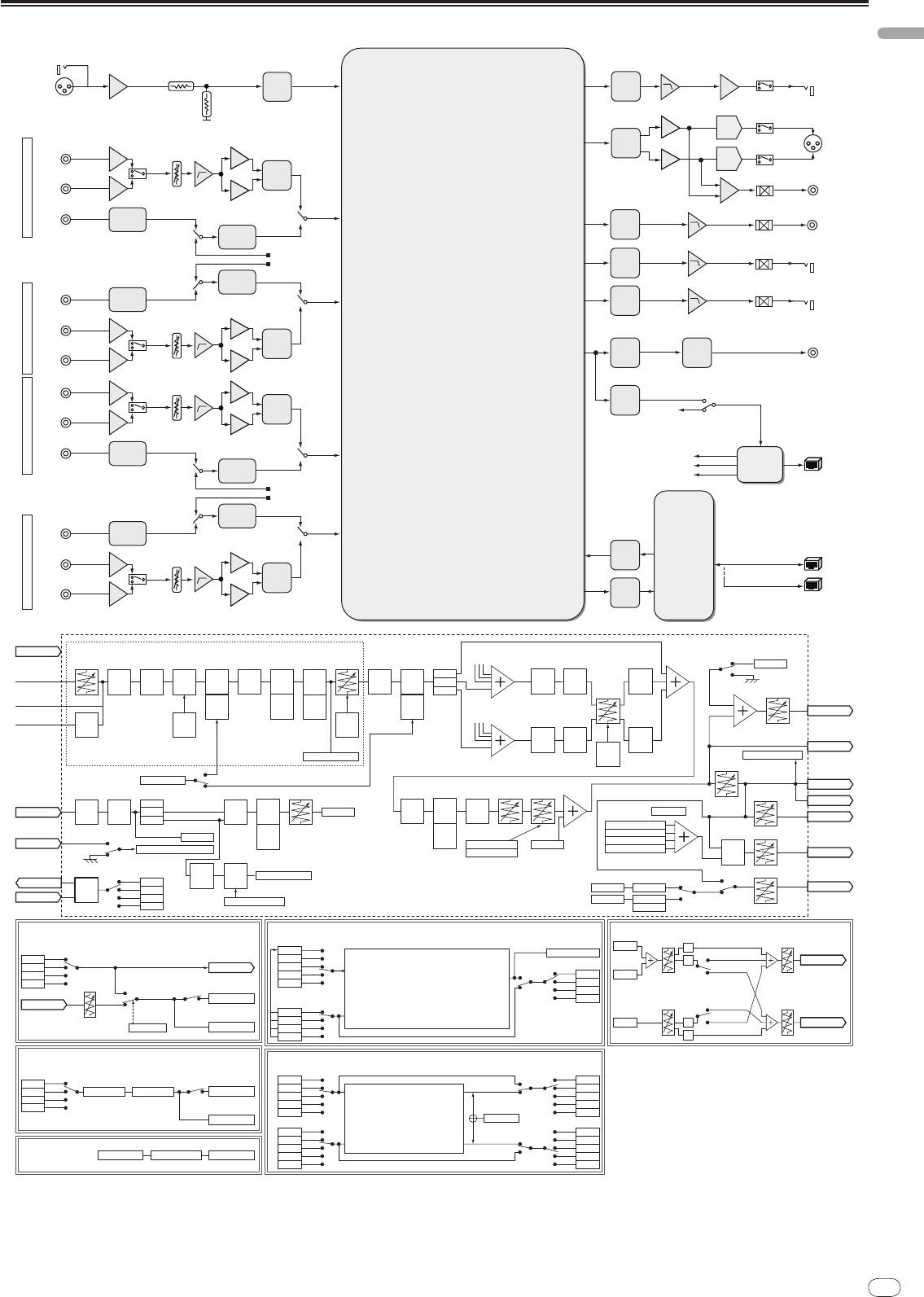
Block Diagram
English
En
27
DRB1497-B
2726
MIC
PHONES
ADC
MIC
PHONES
DAC
MASTER1
CD
MASTER
DAC
TRIM
PHONO
ADC
MASTER2MUTE
CH1CH2CH3CH4
RECMUTE
DIR
CH1
REC
DAC
DIGITAL IN
SRC
USB AUDIO
BOOTHMUTE
DATA
BOOTH
DAC
SRC
DIGITAL IN
MUTE
SEND
DIR
CH2
SEND
DAC
CD
TRIM
DSP
ADC
DIGITAL OUT
LINE
D_OUT
SRC
DIT
CD
TRIM
SRC
LINE
ADC
CH4 DIGITAL/USB SELECT
USB
DIR
Type B
CH3
CH3 DIGITAL/USB SELECT
DIGITAL IN
CH2 DIGITAL/USB SELECT
USB IC
SRC
CH1 DIGITAL/USB SELECT
USB AUDIO
DATA
SRC
DIGITAL IN
DIR
CH4
LAN×5
CD
LAN IN
SRC
I/F
TRIM
con
ADC
PHONO
LAN OUT
SRC
CHn In 1-4
CH1-CH4 COMMON
Assign A
MIC Monitor SW
Digital Trim CHn Fader
CF Assign
CH1- 4
MIC Data2
Digital/USB in
BPM
REMIX
3Band
REMIX
INST FX
BEAT
CUE
BEAT
MIX
Thru
BPM
Send
BEAT
detect
detect
EQ
CH sel2
[ch1-4]
EFFECTS
Monitor
EFFECTS
CH(x, y)
CF_A
detect
Return
CROSS
EFFECTS
CH sel1
Trigger
CH 1-4
[CHx(pre)]
[CH1- 4]
[CHx(post)]
CF_B
[CF_A]
[CF_A]
Fader
[CF_A(post)]
Booth Level
Analog in
REMIX
*1
Send
EFFECT
*2, 3
MIX
3posi
*5 *4 *2, 3
CUE
Return
CUE
CUE
Assign B
PHONO
EQ
[CHx]
[EFFECT]
Booth Out
Phono
CH
CH1- 4
AMP
Isolator
*2, 3, 4
Fader
CH2,3
Switch
Curve
BPM
Send
BEAT
CHx MIX
2posi
3posi
detect
Return
EFFECTS
Data
[CF_B]
[CF_B]
Cross
[CF_B(post)]
Rec Out
Ch1- 4 Level Meter
*5
*4
Fader
Master Level Meter
Curve
*2, 3
Master Level
3posi
Mix/Remix SW
Master
Master Out1
MIC SW
Master Balance
Balance
Talk Over
Digital Level
2Band
MIC1
Off
BPM
BEAT
BPM
BEAT
Master
Master Out2
MIC1 In
MIC
L/R
On
detect
EFFECTS
MIC Data2
detect
EFFECTS
Mono<=>
Master CUE
EQ
TalkOver
[MIC]
[MIC]
[Master]
[Master]
Stereo
Digital Out
3posi
*5
Send
*5
Send
CHx CUE
CUE SW
MIC Data1
Return
Return
EFFECT CUE
H.P. Level
Link In
[MIC]
[Master]
Talk Over On/Off
MIC Data2
Mix/Remix CUE
H.P.
Link/Live Sampler CUE
Link/Live Sampler CUE
- Browsing Monitor
*2, 4
*2, 4
Talk Over Level
MIX
H.P. Out
- Live Sampler Monitor
*1: Same effect processing for channels 1 to 4.
MIC
MIC In
Master Data
EFFECT CH SELECT
*2: Effect processing for setting selected with effect channel select switch.
Filter
level
Talk Over On/Off
Rec Level
BEAT
CH1- 4
*3: The effect input position is set to either before or after the fader, depending on the effect’s
Mic SW
Send Out
detect
EFFECTS
CF_A/B
specifications.
MIC Data1
Off
Link Out
Return In
(SND/RTN)
MIC
*4: When SND/RTN is selected, the channel set with the effect channel select switch is
Talk Over threshold
sent/returned.
MIC Data2
On
Live Sampler
- Live Sampler
Master
*5: Detects the BPM for the channel selected with the effect channel select switch.
Talk Over
Source Select
[BEAT EFFECT
(
SND/RTN)]
[REMIX]
[H.P. MIX]
CUE
Trigger CH SELECT
Balance
H.P.Level
EFFECT CH SELECT
CHx CUE
SAME
L
Remix CUE
CH1- 4
CH1
Mono Split
Remix
R
H.P. Out Lch
CF_A/B
SEND Out
CH2
Remix Effect CH
Stereo
MIC
CH3
On/Off
CH1
Effect CUE
Master
No Cable
Return Level
CH4
CH2
Effect SW
Remix processing
CH3
Effect Out
Remix Effect CH
CH4
Master
Return In
Balance
Mono Split
H.P.Level
Cable Exist
CH1
CH2
Master CUE
L
Stereo
H.P. Out Rch
CableCheck
Effect CUE
CH3
CH4
R
BEAT EFFECT (ETC.)
[MIX]
EFFECT CH SELECT
Assign X Assign X
CH1- 4
Effect SW
CH1
CH1
CF_A/B
EFFECTprocessing
MIX RATIO
Effect Out
CH2
CH2
MIC
CH3
Mix
CH3
Master
CH4
On/Off
CH4
THRU
THRU
Effect CUE
Mix processing
Mix CUE
Assign YAssign Y
CH1
CH1
CH2
CH2
CH3
CH3
INST FX
CH1- 4 In CH1- 4 Out
INST FXprocessing
CH4
Mix
CH4
THRU
On/Off
THRU

28
En
DRB1497-B
Specifications
General
Power requirements ..................................................... AC 220 V to 240 V, 50 Hz/
60 Hz
Power consumption .................................................................................................42 W
Power consumption (standby) ...............................................................................0.4 W
Main unit weight ..................................................................................................... 8.5 kg
External dimensions ..................................430 mm (W) x 107.9 mm (H) x 409 mm (D)
Tolerable operating temperature .........................................................+5 °C to +35 °C
Tolerable operating humidity ...................................... 5 % to 85 % (no condensation)
Audio Section
Sampling rate ........................................................................................................96 kHz
A/
D, D/
A converter .................................................................................................24 bits
Frequency characteristic
CD/
LINE/
MIC ....................................................................................20 Hz to 20 kHz
S/
N ratio (rated output)
PHONO ............................................................................................................. 93 dB
CD/
DIGITAL, LINE ...........................................................................................107 dB
MIC .................................................................................................................... 85 dB
Total harmonic distortion (LINE — MASTER1)................................................. 0.004 %
Standard input level / Input impedance
PHONO ..............................................................................................–52 dBu/
47 kW
CD/
LINE ............................................................................................. –12 dBu/
47 kW
MIC .......................................................................................................–52 dBu/
8 kW
RETURN ............................................................................................. –12 dBu/
47 kW
Standard output level / Load impedance / Output impedance
MASTER1 .....................................................................+8 dBu/
10 kW/
1 W or lower
MASTER2 ...................................................................+2 dBu/
10 kW/
22 W or lower
REC OUT ......................................................................–8 dBu/
10 kW/
22 W or lower
BOOTH .......................................................................+8 dBu/
10 kW/
1 kW or lower
SEND ..........................................................................–12 dBu/
10 kW/
1 kW or lower
PHONES .......................................................................+8.5 dBu/
32 W/
1 W or lower
Rated output level / Load impedance
MASTER1 .........................................................................................+26 dBu/
10 kW
MASTER2 .........................................................................................+20 dBu/
10 kW
Crosstalk (LINE) ...................................................................................................... 82 dB
Channel equalizer characteristic
HI ...................................................................................... –26 dB to +6 dB (13 kHz)
MID ....................................................................................–26 dB to +6 dB (1 kHz)
LOW ....................................................................................-26 dB to +6 dB (70 Hz)
Microphone equalizer characteristic
HI .................................................................................... –12 dB to +12 dB (10 kHz)
LOW ...............................................................................–12 dB to +12 dB (100 Hz)
Input / Output terminals
PHONO input terminal
RCA pin jack ............................................................................................................ 2
CD input terminal
RCA pin jack ............................................................................................................ 4
LINE input terminal
RCA pin jack ............................................................................................................ 2
MIC input terminal
XLR connector/
Phone jack (Ø 6.3 mm) ................................................................ 1
RETURN Input terminals
Phone jack (Ø 6.3 mm) ........................................................................................... 1
DIGITAL IN coaxial input terminal
RCA pin jack ............................................................................................................ 4
MASTER output terminal
XLR connector ......................................................................................................... 1
RCA pin jack ............................................................................................................ 1
BOOTH output terminal
Phone jack (Ø 6.3 mm) ........................................................................................... 1
REC OUT output terminal
RCA pin jack ............................................................................................................ 1
SEND output terminal
Phone jack (Ø 6.3 mm) ........................................................................................... 1
DIGITAL OUT coaxial output terminal
RCA pin jack ............................................................................................................ 1
MIDI OUT terminal
5P DIN ...................................................................................................................... 1
PHONES output terminal
Stereo phone jack (Ø 6.3 mm) ............................................................................... 1
USB terminal
B-type ....................................................................................................................... 1
CONTROL terminal
Mini phone jack (Ø 3.5 mm) ................................................................................... 2
LINK terminal
LAN terminal (100Base-TX) ................................................................................... 6
The specifications and design of this product are subject to change without
notice.
28
DRB1497-B
2928
2
Fr
DRB1497-B
Nous vous remercions d’avoir acquis un produit Pioneer. Veuillez lire attentivement ce mode d’emploi afin de connaître la manière d’utiliser l’appareil comme il
convient. Cela fait, conservez le mode d’emploi de façon à pouvoir vous y référer en cas de nécessité.
Dans certains pays ou certaines régions, la forme de la fiche d’alimentation et de la prise d’alimentation peut différer de celle qui figure sur les schémas, mais les bran-
chements et le fonctionnement de l’appareil restent les mêmes.
30
IMPORTANT
ATTENTION
DANGER D´ELECTROCUTION
NE PAS OUVRIR
Ce symbole de l’éclair, placé dans un
ATTENTION :
Ce point d’exclamation, placé dans un
triangle équilatéral, a pour but d’attirer
POUR ÉVITER TOUT RISQUE
triangle équilatéral, a pour but d’attirer
l’attention de l’utilisateur sur la présence, à
D’ÉLECTROCUTION, NE PAS ENLEVER LE
l’attention de l’utilisateur sur la présence,
l’intérieur du coffret de l’appareil, de
COUVERCLE (NI LE PANNEAU ARRIÈRE).
dans les documents qui accompagnent
“tensions dangereuses” non isolées d’une
AUCUNE PIÈCE RÉPARABLE PAR
l’appareil, d’explications importantes du
grandeur suffisante pour représenter un
L’UTILISATEUR NE SE TROUVE À
point de vue de l’exploitation ou de
risque d’électrocution pour les êtres
L’ INTÉRIEUR. CONFIER TOUT ENTRETIEN À
l’entretien.
humains.
UN PERSONNEL QUALIFIÉ UNIQUEMENT.
D3-4-2-1-1_A1_Fr
Si vous souhaitez vous débarrasser de cet appareil, ne le mettez pas à la poubelle avec vos ordures ménagères. Il existe un système de
collecte séparé pour les appareils électroniques usagés, qui doivent être récupérés, traités et recyclés conformément à la législation.
Les habitants des états membres de l’UE, de Suisse et de Norvège peuvent retourner gratuitement leurs appareils électroniques usagés aux
centres de collecte agréés ou à un détaillant (si vous rachetez un appareil similaire neuf).
Dans les pays qui ne sont pas mentionnés ci-dessus, veuillez contacter les autorités locales pour savoir comment vous pouvez vous débarrasser
de vos appareils.
Vous garantirez ainsi que les appareils dont vous vous débarrassez sont correctement récupérés, traités et recyclés et préviendrez de cette façon
les impacts néfastes possibles sur l’environnement et la santé humaine.
K058b_A1_Fr

Fr
3
DRB1497-B
3130
AVERTISSEMENT
Si la fiche d’alimentation secteur de cet appareil ne
Cet appareil n’est pas étanche. Pour éviter les risques
convient pas à la prise secteur à utiliser, la fiche doit
d’incendie et de décharge électrique, ne placez près de
être remplacée par une appropriée. Ce
lui un récipient rempli d’eau, tel qu’un vase ou un pot
remplacement et la fixation d’une fiche secteur sur le
de fleurs, et ne l’exposez pas à des gouttes d’eau, des
cordon d’alimentation de cet appareil doivent être
éclaboussures, de la pluie ou de l’humidité.
effectués par un personnel de service qualifié. En cas
D3-4-2-1-3_A1_Fr
de branchement sur une prise secteur, la fiche de
coupure peut provoquer une sérieuse décharge
AVERTISSEMENT
électrique. Assurez-vous qu’elle est éliminée
Avant de brancher l’appareil pour la première, lisez
correctement après sa dépose.
attentivement la section suivante.
L’ appareil doit être déconnecté en débranchant sa
La tension de l’alimentation électrique disponible
fiche secteur au niveau de la prise murale si vous
varie selon le pays ou la région. Assurez-vous que
prévoyez une période prolongée de non utilisation
la tension du secteur de la région où l’appareil sera
(par exemple avant un départ en vacances).
utilisé correspond à la tension requise (par ex. 230
D3-4-2-2-1a_A1_Fr
V ou 120 V), indiquée sur le panneau arrière.
D3-4-2-1-4*_A1_Fr
ATTENTION
L’ interrupteur POWER de cet appareil ne coupe pas
AVERTISSEMENT
complètement celui-ci de sa prise secteur. Comme le
Pour éviter les risques d’incendie, ne placez aucune
cordon d’alimentation fait office de dispositif de
flamme nue (telle qu’une bougie allumée) sur
déconnexion du secteur, il devra être débranché au
l’appareil.
niveau de la prise secteur pour que l’appareil soit
D3-4-2-1-7a_A1_Fr
complètement hors tension. Par conséquent, veillez à
installer l’appareil de telle manière que son cordon
PRÉCAUTION DE VENTILATION
d’alimentation puisse être facilement débranché de
Lors de l’installation de l’appareil, veillez à laisser un
la prise secteur en cas d’accident. Pour éviter tout
espace suffisant autour de ses parois de manière à
risque d’incendie, le cordon d’alimentation sera
améliorer la dissipation de chaleur (au moins 5 cm à
débranché au niveau de la prise secteur si vous
l’arrière et 3 cm de chaque côté).
prévoyez une période prolongée de non utilisation
(par exemple avant un départ en vacances).
AVERTISSEMENT
D3-4-2-2-2a*_A1_Fr
Les fentes et ouvertures du coffret sont prévues pour la
ventilation, pour assurer un fonctionnement stable de
l’appareil et pour éviter sa surchauffe. Pour éviter les
NOTE IMPORTANTE SUR LE CABLE
risques d’incendie, ne bouchez jamais les ouvertures et
D’ALIMENTATION
ne les recouvrez pas d’objets, tels que journaux, nappes
Tenir le câble d’alimentation par la fiche. Ne pas
ou rideaux, et n’utilisez pas l’appareil posé sur un tapis
débrancher la prise en tirant sur le câble et ne pas
épais ou un lit.
toucher le câble avec les mains mouillées. Cela risque
D3-4-2-1-7b*_A1_Fr
de provoquer un court-circuit ou un choc électrique. Ne
pas poser l’appareil ou un meuble sur le câble. Ne pas
Milieu de fonctionnement
pincer le câble. Ne pas faire de noeud avec le câble ou
Température et humidité du milieu de fonctionnement :
l’attacher à d’autres câbles. Les câbles d’alimentation
De +5 °C à +35 °C (de +41 °F à +95 °F) ; Humidité
doivent être posés de façon à ne pas être écrasés. Un
relative inférieure à 85 % (orifices de ventilation non
câble abîmé peut provoquer un risque d’incendie ou un
obstrués)
choc électrique. Vérifier le câble d’alimentation de
N’installez pas l’appareil dans un endroit mal ventilé ou
temps en temps. Contacter le service après-vente
un lieu soumis à une forte humidité ou en plein soleil
PIONEER le plus proche ou le revendeur pour un
(ou à une forte lumière artificielle).
remplacement.
D3-4-2-1-7c*_A1_Fr
S002*_A1_Fr
Оглавление
- Contents
- Before start
- Connections
- Operations
- Changing the settings
- Additional information
- Sommaire
- Informations
- Raccordements
- Opérations
- Changement des réglages
- Informations supplémentaires
- Inhalt
- Vor der
- Anschlüsse
- Bedienungen
- Ändern der Einstellungen
- Zusätzliche Informationen
- Indice
- Prima di cominciare
- Collegamenti
- Operazioni
- Modifica delle impostazioni
- Informazioni aggiuntive
- Inhoud
- Alvorens te
- Aansluitingen
- Bediening
- Instellingen aanpassen
- Aanvullende informatie
- Contenido
- Antes de empezar a
- Conexiones
- Operaciones
- Cambio de los ajustes
- Información adicional
- Содержание
- До начала
- Подключения
- Операции
- Изменение настроек
- Дополнительная информация


