Pioneer GM-D8604: Connecting the units
Connecting the units: Pioneer GM-D8604
Section
03
Connecting the units
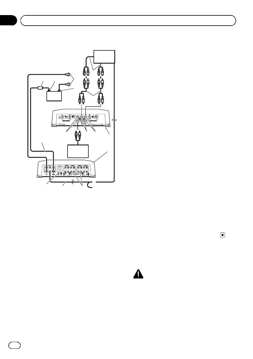
7 Car stereo with RCA output jacks (sold sepa-
Connection diagram
rately)
8 External output
7
If only one input plug is used, do not connect
anything to RCA input jack B.
8
9 Connecting wire with RCA pin plugs (sold se-
2
3
6
parately)
a RCA input jack A
4
b RCA input jack B
5
9
c Amplifier with RCA input jacks (sold sepa-
rately)
d RCA output jack
Outputs the signal input to CH A.
e Speaker output terminals
Please see the following section for speaker
d
a
b
connection instructions. Refer to Connections
h
1
when using the speaker input wire on page 9.
f System remote control wire (sold separately)
i
c
Connect male terminal of this wire to the sys-
tem remote control terminal of the car stereo.
The female terminal can be connected to the
auto-antenna relay control terminal. If the car
stereo lacks a system remote control terminal,
g
connect the male terminal to the power term-
f
e
inal via the ignition switch.
1 Battery wire (sold separately)
g Fuse (30 A) × 2
! The maximum length of the wire be-
h Front side
tween the fuse and the positive + term-
i Rear side
inal of the battery is 30cm.
Note
! For the wire size, refer to Connecting the
INPUT SELECT (input select) switch must be set.
power terminal on page 10. The battery
For details, see Setting the unit on page 4.
wire, the ground wire and the optional
direct ground wire must be same size.
After making all other connections at
the amplifier, connect the battery wire
Before connecting the
terminal of the amplifier to the positive
amplifier
+ terminal of the battery.
2 Fuse (80 A) (sold separately)
WARNING
Each amplifier must be separately fused at
! Secure the wiring with cable clamps or adhe-
80 A.
sive tape. To protect the wiring, wrap sections
3 Positive (+) terminal
in contact with metal parts in adhesive tape.
4 Negative (*) terminal
! Never cut the insulation of the power supply
5 Battery (sold separately)
to feed power to other equipment. Current ca-
6 Ground wire, Terminal (sold separately)
pacity of the wire is limited.
The ground wires must be same size as the
battery wire.
Connect to metal body or chassis.
6
En
Section
Connecting the units
03
English
In addition, refer to the speaker instruction
CAUTION
manual for information on the correct connec-
! Never shorten any wires, the protection circuit
tion procedure.
may malfunction.
! For any further enquiries, contact your local
! Never wire the speaker negative cable directly-
authorized Pioneer dealer or customer
to ground.
service.
! Never band together multiple speaker’s nega-
tive cables.
! If the system remote control wire of the ampli-
About suitable
fier is connected to the power terminal via the
ignition switch (12V DC), the amplifier will re-
specification of speaker
main on with the ignition whether the car
Ensure speakers conform to the following
stereo is on or off, which may exhaust battery
standards, otherwise there is a risk of fire,
if the engine is at rest or idling.
smoke or damage. Speaker impedance is 2 W
! Install and route the separately sold battery
to 8 W,or4W to 8 W for two-channel and other
wire as far as possible from the speaker wires.
bridge connections.
Install and route the separately sold battery
wire, ground wire, speaker wires and the am-
Subwoofer
plifier as far away as possible from the anten-
Speaker channel Power
na, antenna cable and tuner.
Nominal input:
Four-channel output
Min. 100 W
About bridged mode
Nominal input:
Two-channel output
Min. 300 W
Speaker output
Nominal input:
A
Min. 100 W
Three-channel
output
Speaker output
Nominal input:
B
Min. 300 W
Other than subwoofer
Speaker channel Power
Max. input:
Four-channel output
Min. 200 W
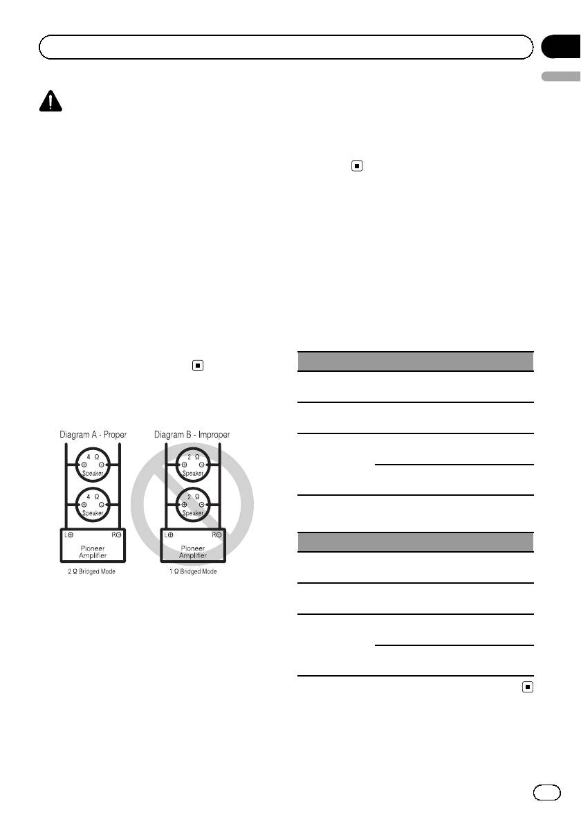
! Do not install or use this amplifier by wiring
Max. input:
Two-channel output
speakers rated at 2 W (or lower) in parallel to
Min. 600 W
achieve a 1 W (or lower) bridged mode (Dia-
Speaker output
Max. input:
gram B).
A
Min. 200 W
Three-channel
Amplifier damage, smoke, and overheating
output
Speaker output
Max. input:
could result from improper bridging. The am-
B
Min. 600 W
plifier surface could also become hot to the
touch and minor burns could result.
To properly install or use a bridged mode and
achieve a 2 W load, wire two 4 W speakers in
parallel with Left + and Right * (Diagram A)
or use a single 2W speaker.
7
En
Section
03
Connecting the units
Two-channel output (Mono)
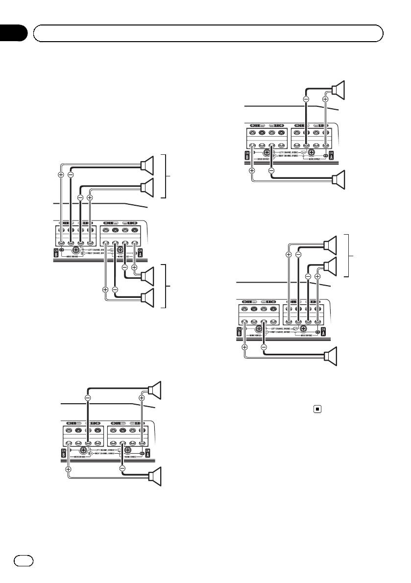
Connecting the speakers
The speaker output mode can be four-channel,
1
three-channel (stereo and mono) or two-chan-
nel (stereo or mono). Connect the speaker
leads based on the mode and the figures
shown below.
Four-channel output
1
4
1
2
1 Speaker output (Mono)
Three-channel output
1
3
2
2
3
1
1 Left
2 Right
3 Speaker output A
4 Speaker output B
4
Two-channel output (Stereo)
1 Left
1
2 Right
3 Speaker output A
4 Speaker output B (Mono)
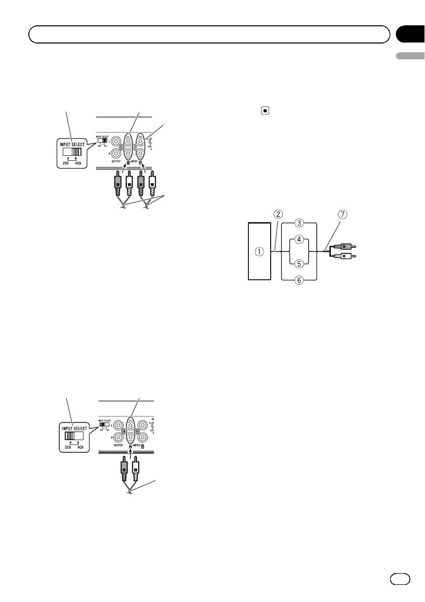
Connections when using
the RCA input jack
Connect the car stereo RCA output jack and
2
the RCA input jack of the amplifier.
! The RCA output jack of this unit outputs
1 Speaker output (Right)
the signal that comes from The RCA input
2 Speaker output (Left)
jack A.
8
En
Section
Connecting the units
03
English
Four-channel / Three-channel output
2 Connecting wire with RCA pin plugs (sold se-
! Slide INPUT SELECT (input select) switch
parately)
to 4CH position.
3 From car stereo (RCA output)
4 INPUT SELECT (input select) switch (2CH
5
1
position)
2
Connections when using
the speaker input wire
Connect the car stereo speaker output wires
to the amplifier using the supplied speaker
3
input wire with RCA pin cord.
4
1 RCA input jack A
2 RCA input jack B
3 Connecting wires with RCA plugs (sold sepa-
rately)
4 From car stereo (RCA output)
If only one input plug is used, e.g. when the
car stereo has only one output (RCA output),
1 Car Stereo
connect the plug to RCA input jack A rather
2 Speaker output
than B.
3 Red: Right +
5 INPUT SELECT (input select) switch (4CH po-
4 Black: Right *
sition)
5 Black: Left *
6 White: Left +
Two-channel output (Stereo) / (Mono)
7 Speaker input wire with RCA pin cord
! Slide INPUT SELECT (input select) switch
To the RCA input jack of this unit
to 2CH position.
4
1
Notes
! If speaker wires with an RCA pin cord from a
headunit are connected to this amplifier, the
amplifier will automatically turn on when the
headunit is turned on. When the headunit is
turned off, the amplifier turns off automati-
cally. This function may not work with some
headunits. In such cases, please use a sys-
2
tem remote control wire (sold separately). If
multiple amplifiers are to be connected to-
3
gether synchronously, connect the head unit
and all amplifiers via the system remote con-
1 RCA input jack A
trol wire.
For two-channel output, connect the RCA
! Connect the system remote control wire when
plugs to the RCA input jack A.
you wish to only turn on the car stereo, not the
amplifier.
9
En
Section
03
Connecting the units
! This amplifier automatically selects an input
Battery wire and ground wire size
signal mode between the RCA level and the
Wire length Wire size
speaker level by detecting an input signal.
less than 4.5 m 8 AWG
less than 7.2 m 6 AWG
Solderless terminal
less than 11.4 m 4 AWG
connections
! Since the wire will become loose over time,
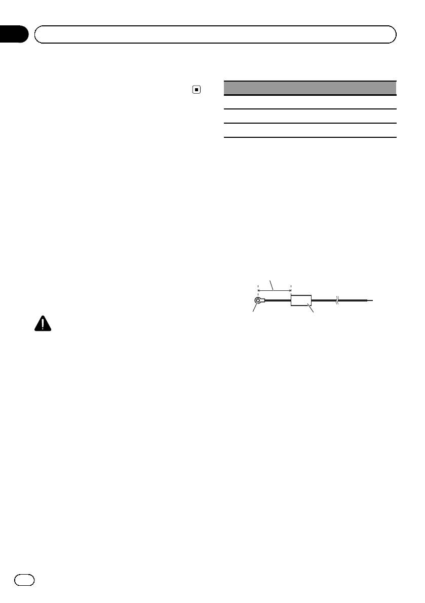
1 Route battery wire from engine com-
it must be periodically inspected and tigh-
partment to the vehicle interior.
tened as necessary.
! When drilling a cable pass-hole into the ve-
! Do not solder or bind the ends of the
hicle body and routing a battery wire thor-
twisted wires.
ough it, take care not to short-circuit the
! Fasten while making sure to not to clamp
wire damaging it by the cut edges or burrs
the insulating sheath of the wire.
of the hole.
! Use the supplied hexagonal wrench to
After completing all other amplifier connec-
tighten and loosen the terminal screw of
tions, finally connect the battery wire terminal
the amplifier and use it to securely fasten
of the amplifier to the positive (+) battery
the wire. Be careful to avoid excessive tigh-
terminal.
tening of this screw, which may damage
2
the wire.
Connecting the power terminal
1
3
WARNING
1 Positive (+) terminal
If the battery wire is not securely fixed to the term-
2 Battery wire (sold separately)
inal using the terminal screws, there is a risk of
The maximum length of the wire between
overheating, malfunction and injury, including
the fuse and the positive + terminal of the
minor burns.
battery is 30 cm.
3 Fuse (80 A) (sold separately)
! Always use the recommended battery and
Each amplifier must be separately fused at
ground wire, which is sold separately. Con-
80 A.
nect the battery wire directly to the car bat-
tery positive (+) terminal and the ground
wire to the car body.
! Recommended wires size (AWG: American
Wire Gauge) is as follows. The battery wire,
the ground wire and the optional direct
ground wire must be same size.
! Use a wire of 8 AWG to 16 AWG wire for the
speaker wire.
10
En
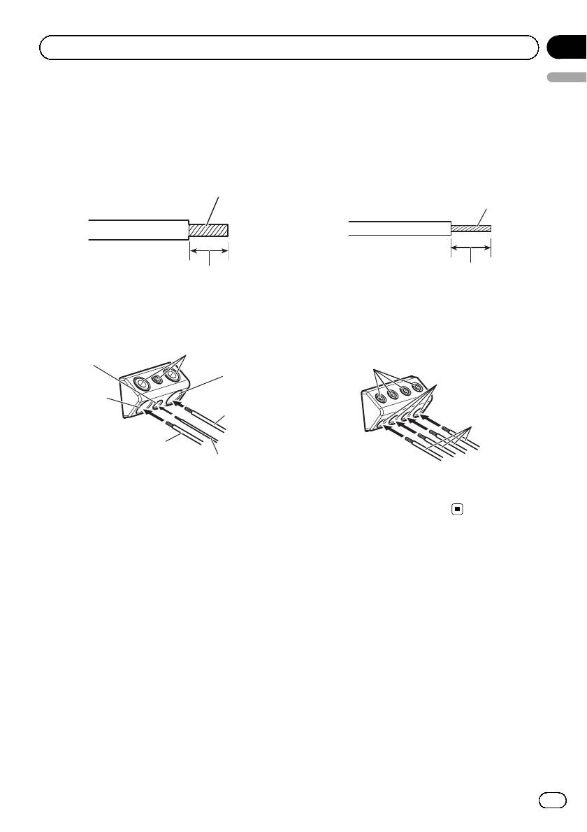
2 Use wire cutters or a utility knife to
strip the end of the battery wire, ground
wire and system remote control wire to ex-
pose about 10 mm of the end of each of
the wires, and then twist the exposed ends
of the wires.
Twist
10 mm
3 Connect the wires to the terminal.
Fix the wires securely with the terminal
screws.
7
6
2
4
1
5
Section
Connecting the units
03
English
Connecting the speaker output
terminals
1 Use wire cutters or a utility knife to
strip the end of the speaker wires to ex-
pose about 10 mm of wire and then twist
the wire.
Twist
10 mm
2 Connect the speaker wires to the
speaker output terminals.
Fix the wires securely with the terminal
screws.
1
3
2
3
1 Battery wire
1 Terminal screws
2 Power terminal
2 Speaker wires
3 Ground wire
3 Speaker output terminals
4 GND terminal
5 System remote control wire
6 System remote control terminal
7 Terminal screws
11
En
Оглавление
- Before you start
- Setting the unit
- Connecting the units
- Installation Before installing the amplifier Example of insta llation on the floor mat or chassis
- Additional information
- Avant de commencer
- Réglage de l’appareil
- Connexion des appareils
- Installation
- Informations complémentaires
- Prima di iniziare
- Impostazione dell’unità
- Collegamento delle unità
- Collegamento delle unità Prima di collegare Informazioni sulla modalità l’amplificatore di collegamento a ponte
- Collegamento delle unità
- Installazione
- Informazioni supplementari
- Antes de comenzar
- Configuración de la unidad
- Conexión de las unidades
- Instalación
- Información adicional
- Bevor Sie beginnen
- Einstellen des Geräts
- Anschließen der Geräte
- Anschließen der Geräte Vor dem Anschluss des Zum Überbrückungsmodus Verstärkers
- Anschließen der Geräte
- Installation
- Zusätzliche Informationen
- Vóór u begint
- Het toestel installeren
- De toestellen aansluiten
- De toestellen aansluiten Vóór u de versterker aansluit Informatie over de brugschakeling
- De toestellen aansluiten
- Installatie
- Aanvullende informatie
- Перед началом эксплуатации
- Настройка усилителя
- Подключение устройств
- Установка
- Дополнительная информация


