Pioneer GM-D8601: Connecting the units
Connecting the units: Pioneer GM-D8601
Section
Connecting the units
03
English
1 Route battery wire from engine com-
7
partment to the vehicle interior.
6
! When drilling a cable pass-hole into the ve-
2
hicle body and routing a battery wire thor-
4
ough it, take care not to short-circuit the
1
wire damaging it by the cut edges or burrs
of the hole.
After completing all other amplifier connec-
3
tions, finally connect the battery wire terminal
5
of the amplifier to the positive (+) battery
1 Battery wire
terminal.
2 Power terminal
2
3 Ground wire
4 GND terminal
5 System remote control wire
6 System remote control terminal
1
3
7 Terminal screws
1 Positive (+) terminal
2 Battery wire (sold separately)
Connecting the speaker output
The maximum length of the wire between
terminals
the fuse and the positive + terminal of the
1 Use wire cutters or a utility knife to
battery is 30 cm.
strip the end of the speaker wires to ex-
3 Fuse 100 A (GM-D8601) / 150 A (GM-D9601)
pose about 10 mm of wire and then twist
(sold separately)
the wire.
Each amplifier must be separately fused at
100 A (GM-D8601) / 150 A (GM-D9601).
Twist
2 Use wire cutters or a utility knife to
strip the end of the battery wire, ground
wire and system remote control wire to ex-
pose about 10 mm of the end of each of
10 mm
the wires, and then twist the exposed ends
of the wires.
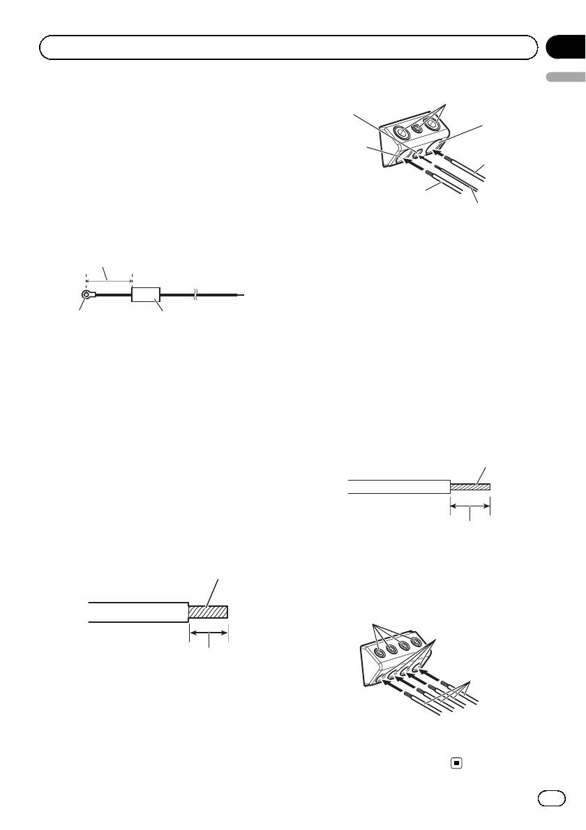
2 Connect the speaker wires to the
speaker output terminals.
Twist
Fix the wires securely with the terminal
screws.
1
3
10 mm
2
3 Connect the wires to the terminal.
Fix the wires securely with the terminal
screws.
1 Terminal screws
2 Speaker wires
3 Speaker output terminals
9
En
Оглавление
- Before you start
- Setting the unit
- Connecting the units
- Connecting the units Connections when using Solderless terminal the speaker input wire connections
- Connecting the units
- Installation Before installing the amplifier Attaching the Bass boost remote control
- Installation
- Additional information
- Avant de commencer
- Réglage de l’appareil
- Connexion des appareils
- Installation
- Informations complémentaires
- Prima di iniziare
- Impostazione dell’unità
- Collegamento delle unità
- Installazione
- Informazioni supplementari
- Antes de comenzar
- Configuración de la unidad
- Conexión de las unidades
- Instalación
- Información adicional
- Bevor Sie beginnen
- Einstellen des Geräts
- Anschließen der Geräte
- Installation
- Zusätzliche Informationen
- Vóór u begint
- Het toestel installeren
- De toestellen aansluiten
- De toestellen aansluiten Aansluiting via de luidspre- Aansluitingen niet solderen keringangskabel
- De toestellen aansluiten
- Installatie
- Aanvullende informatie
- Перед началом эксплуатации
- Настройка усилителя
- Подключение устройств
- Установка
- Установка Пример установки усилителя на напольном коврике или шасси
- Дополнительная информация


