Pioneer GM-D8601: Connecting the units
Connecting the units: Pioneer GM-D8601
Section
03
Connecting the units
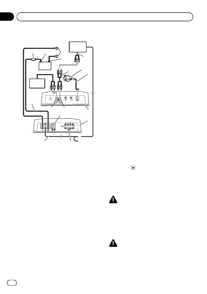
7 Car stereo with RCA output jacks (sold sepa-
Connection diagram
rately)
8 External output
7
9 Connecting wire with RCA pin plugs (sold se-
2
3
6
parately)
4
8
a Amplifier with RCA input jacks (sold sepa-
rately)
5
b
9
b Bass boost level remote control
c
c Bass boost level remote control wire (5 m)
d RCA input jack
a
e RCA output jack
f System remote control wire (sold separately)
Connect male terminal of this wire to the sys-
1
tem remote control terminal of the car stereo.
The female terminal can be connected to the
e
d
i
auto-antenna relay control terminal. If the car
h
stereo lacks a system remote control terminal,
j
connect the male terminal to the power term-
inal via the ignition switch.
g Speaker output terminals
Please see the following section for speaker
f
connection instructions. Refer to Connections
g
when using the speaker input wire on page 8.
1 Battery wire (sold separately)
h Fuse 40 A × 2 (GM-D8601) / 40 A × 3 (GM-
! The maximum length of the wire be-
D9601)
tween the fuse and the positive + term-
i Front side
inal of the battery is 30 cm.
j Rear side
! For the wire size, refer to Connecting the
power terminal on page 8. The battery
wire, the ground wire and the optional
Before connecting the
direct ground wire must be same size.
amplifier
After making all other connections at
the amplifier, connect the battery wire
WARNING
terminal of the amplifier to the positive
! Secure the wiring with cable clamps or adhe-
+ terminal of the battery.
sive tape. To protect the wiring, wrap sections
2 Fuse 100 A (GM-D8601) / 150 A (GM-D9601)
in contact with metal parts in adhesive tape.
(sold separately)
! Never cut the insulation of the power supply
Each amplifier must be separately fused at
to feed power to other equipment. Current ca-
100 A (GM-D8601) / 150 A (GM-D9601).
pacity of the wire is limited.
3 Positive (+) terminal
4 Negative (*) terminal
CAUTION
5 Battery (sold separately)
6 Ground wire, Terminal (sold separately)
! Never shorten any wires, the protection circuit
The ground wires must be same size as the
may malfunction.
battery wire.
! Never wire the speaker negative cable directly-
Connect to metal body or chassis.
to ground.
6
En
Section
Connecting the units
03
English
! Never band together multiple speaker’s nega-
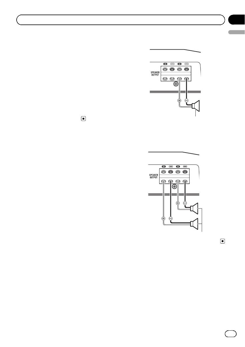
When connecting to one speaker
tive cables.
! If the system remote control wire of the ampli-
fier is connected to the power terminal via the
ignition switch (12 V DC), the amplifier will re-
main on with the ignition whether the car
stereo is on or off, which may exhaust battery
if the engine is at rest or idling.
! Install and route the separately sold battery
wire as far as possible from the speaker wires.
Install and route the separately sold battery
wire, ground wire, speaker wires and the am-
plifier as far away as possible from the anten-
na, antenna cable and tuner.
Speaker output
When connecting to two speakers
The output from two speakers is the same as
Connecting the speakers
that of one speaker.
This amplifier can be connected to two speak-
ers in parallel. Connect the speaker leads to
suit the mode according to the figure shown
below.
Precautions for parallel connection
! When wiring two speakers in parallel, make
sure that the synthetic impedance is from
1 W to 8 W to prevent the amplifier from
catching fire, generating smoke and/or
being damaged.
! When connected in parallel with the syn-
thetic impedance less than 1 W, as a nor-
mal function, this amplifier may
automatically be set on mute if outputting
Speaker output
high volume sound. Turn down the volume
until the mute function is canceled.
7
En
Оглавление
- Before you start
- Setting the unit
- Connecting the units
- Connecting the units Connections when using Solderless terminal the speaker input wire connections
- Connecting the units
- Installation Before installing the amplifier Attaching the Bass boost remote control
- Installation
- Additional information
- Avant de commencer
- Réglage de l’appareil
- Connexion des appareils
- Installation
- Informations complémentaires
- Prima di iniziare
- Impostazione dell’unità
- Collegamento delle unità
- Installazione
- Informazioni supplementari
- Antes de comenzar
- Configuración de la unidad
- Conexión de las unidades
- Instalación
- Información adicional
- Bevor Sie beginnen
- Einstellen des Geräts
- Anschließen der Geräte
- Installation
- Zusätzliche Informationen
- Vóór u begint
- Het toestel installeren
- De toestellen aansluiten
- De toestellen aansluiten Aansluiting via de luidspre- Aansluitingen niet solderen keringangskabel
- De toestellen aansluiten
- Installatie
- Aanvullende informatie
- Перед началом эксплуатации
- Настройка усилителя
- Подключение устройств
- Установка
- Установка Пример установки усилителя на напольном коврике или шасси
- Дополнительная информация


