AEG VL 5569 S LB: ENGLISH
ENGLISH: AEG VL 5569 S LB

ENGLISH
47
Contents
General Safety Instructions
Overview .........................................................................................3
Read the operating instructions carefully before putting
Assembly overview ......................................................................4
the appliance into operation and keep the instructions in-
General Safety Instructions ...................................................47
cluding the warranty, the receipt and, if possible, the box
Children and Frail Individuals ..............................................47
with the internal packing. If you give this device to other
Symbols in these Instructions for Use ..............................47
people, please also pass on the operating instructions.
Special safety instructions .....................................................48
• The appliance is designed exclusively for private use
General Instructions ................................................................48
and for the envisaged purpose. This appliance is not
Intended Use ...............................................................................48
it for commercial use. Do not use it outdoors. Keep it
Notes on use ...............................................................................48
away from sources of heat, direct sunlight, humidity
Position ..........................................................................................48
(never dip it into any liquid) and sharp edges. Do not
Overview of the components ................................................48
use the appliance with wet hands. If the appliance is
Assembly accessory overview ...............................................48
humid or wet, unplug it immediately.
Unpacking the Device .............................................................49
• When cleaning or putting it away, switch of the appli-
Assembly instructions .............................................................49
ance and always pull out the plug from the socket (pull
Base unit (Fig. a – c) .................................................................49
the plug itself, not the lead) if the appliance is not
Fan (Fig. d)....................................................................................49
being used and remove the attached accessories.
Humidier (Fig. e – f) ..............................................................49
• Do not operate the machine without supervision. If
Water ............................................................................................50
you leave the room you should always turn the device
Fill with water ............................................................................50
o. Remove the plug from the socket.
Putting into Service .................................................................50
• The device and the mains lead have to be checked
Electrical Connection ..............................................................50
regularly for signs of damage. If damage is found the
Fitting batteries into the remote control ........................50
device must not be used.
Remote control range .............................................................50
• Do not try to repair the appliance on your own.
Use .................................................................................................50
Always contact an authorized technician. To avoid
Basic Settings .............................................................................50
the exposure to danger, always have a faulty cable be
Operation .....................................................................................50
replaced only by the manufacturer, by our customer
ON/OFF Switch on/o ......................................................51
service or by a qualiied person and with a cable of the
SPEED Speed ......................................................................51
same type.
TIMER Timer .......................................................................51
• Use only original spare parts.
MODE Wind Change Functions ..................................51
• Pay careful attention to the following “Special Safety
OSC Oscillation .............................................................51
Instructions“.
MOIST Mist ..........................................................................51
Rell water ..................................................................................51
Children and Frail Individuals
Shutting o ................................................................................51
• In order to ensure your children‘s safety, please keep all
Cleaning ......................................................................................51
packaging (plastic bags, boxes, polystyrene etc.) out of
Housing .........................................................................................51
their reach.
Water tank ...................................................................................52
Humidier base..........................................................................52
WARNING!
Troubleshooting ........................................................................52
Caution! Do not allow small children to play with the
Noise development ..................................................................52
foil as there is a danger of suocation!
Technical Data ...........................................................................52
• This device is not intended to be used by individuals
Disposal- Meaning of the “Dustbin” Symbol ..................52
(including children) who have restricted physical, sen-
sory or mental abilities and/or insuicient knowl-edge
and/or experience, unless they are supervised by an
individual who is responsible for their safety or have
received instructions on how to use the device.
• Children should be supervised at all times in order to
ensure that they do not play with the device.
Symbols in these Instructions for Use
Important information for your safety is specially marked.
It is essential to comply with these instructions in order to
avoid accidents and prevent damage to the machine:
48
ENGLISH
Position
WARNING:
The ideal position is a non-slip, at surface.
This warns you of dangers to your health and indicates
possible injury risks.
Overview of the components
CAUTION:
Overview
This refers to possible hazards to the machine or other
1 Hook
objects.
2 Fastening hooks
NOTE:
3 Propeller
This highlights tips and information.
4 Protection grid
5 Mounting screw M2,5*8mm with nut
6 Switch housing
Special safety instructions
7 Stand tubes
8 Tube with tank cap
• Never stick ngers or other objects through the pro-
9 Water tank
tection grid!
10 Humidier base
• Watch out for long hair! It can be caught in the fan
11 Stand with cover
owing to the air turbulence!
• Use the appliance only with the protection grids on!
Assembly overview
• The appliance must be assembled completely before
12 M5*18mm screws
use!
13 Base (Base plate)
• Select a stable base to avoid the tipping of the fan
14 Metal plate with mounting holes
during use!
15 M5 nuts
• Do not place the device immediately next to stoves or
16 Cover of the stand
other sources of heat.
17 M6*10mm screws with nuts
CAUTION:
18 Motor
The integrated humidier works by ultrasound. This
19 Rear protection grid
sound may be disturbing to pets.
20 Nut for rear protection grid
21 Attachment screw for propeller
22 Front protection grid
General Instructions
Intended Use
Not shown
• Remote control
This appliance can be used as a fan and/or humidier.
• ST4*25mm screw for fastening the humidier to the
It is intended exclusively for this purpose and may only be
stand
used as such. It may only be used in the manner described
• M6 nuts to fasten the motor to the stand tubes
in these instructions for use. The device must not be used
for commercial purposes.
Any other use of this device is considered to be contrary
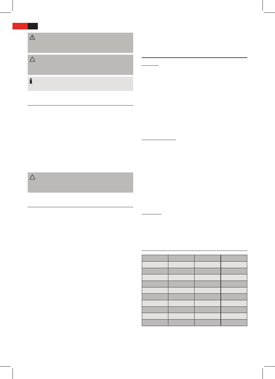
Assembly accessory overview
to the intended use and may result in damage to materi-
Number Quantity Accessories Size
als or even personal injury.
The rm ETV - Elektro-Technische Vertriebsgesellschaft
5 1 Screw M2,5*8mm
mbH does not accept any liability for damage caused as
5 1 Nut M2,5
a result of the use of this device contrary to its intended
12 4 Screws M5*18mm
use.
14 1 Metal plate
15 4 Nuts M5
Notes on use
17 2 Screws M6*10mm
You can use this appliance to increase the air humidity in
20 1 Nut
a dry environment. This oers the following benets:
21 1 Screw
• Provides a healthy indoor environment and is thus
None 1 Screw ST4*25mm
benecial to your well-being.
• Your skin does not dry out as readily.
None 2 Nuts M6
• Static in the air is eliminated.
The appliance works best if doors and windows are kept
closed when used in mist mode.

ENGLISH
49
Unpacking the Device
Fan (Fig. d)
6. Remove the preinstalled nut (20) from the motor (18).
• Remove the device from its packaging.
Keep it close to hand.
•
Remove all of the packaging material such as foils,
7.
Align the rear protection grid (19) with the motor
lling material, cable holders and cardboard packaging.
recesses (18).
• Check the scope of delivery.
NOTE:
NOTE:
The handle must point upwards.
There may still be dust or production residues on the
8. Tighten the nut (20) for the rear
protection grid
clock-
surface of the device. We recommend that you quickly
wise.
wipe of the housing with a damp cloth.
9. Attach the propeller (3). When doing so, use the guide
pin on the motor shaft.
Assembly instructions
10. Tighten the screw (21) for the propeller anti-clockwise.
11. Remove the pretted screw and nut (5) from the front
The appliance must be fully assembled before use! We
protection grid
(22). Keep it close to hand.
recommend that you refer to the gures “Overview” and
12. Open the fastening hooks (2) at the front protection
“Assembly overview” when assembling.
grid.
13. Attach the front
protection grid
by engaging the
Base unit (Fig. a – c)
groove of the hook (1) with the rear
protection grid
.
1. Screw the tubes (7) onto the stand (13). Use the four
screws (12), the metal plate (14), and the four nuts (15).
NOTE:
2. Attach the cover of the stand (16) to the stand tubes.
The holes for the screw (5) in the front and rear
protection grid
must be aligned.
NOTE:
14. Secure the
protection grid
with the screw and the nut
The nuts and screws (17) are preinstalled on the rear of
(5).
the switch housing.
15. Close the four fastening hooks (2).
3. Check if the screws (17) possibly have been screwed
into deeply. In this case, turn the screws back a little.
Humidier (Fig. e – f)
Do not screw them out all the way!
The tube already may have been installed on the switch
NOTE:
housing. In this case, continue the assembly from item 18.
If a screw or a bolt should have dropped o, proceed
16. Feed the tube (8) from front to back between the two
as follows:
stand tubes (7). Then insert the tube from the bottom
• Hold the preassembled unit (motor (18), switch
upwards through the opening on the underside of the
housing (6), and humidier base (10)) so that the
switch housing (6).
motor points down.
NOTE:
• Insert one nut (M6) each into the shaft at the
The end of the tube with the tank cap must be
side of the recesses for the tubes.
positioned at the front above the humidier.
• Screw the two screws (17) on the rear of the
switch housing lightly into the nuts.
17. Insert the tube from the back to the front through the
opening on the top of the switch housing.
4. Set the preassembled unit for a depth of approxi-
18. Pull the tube tight so that it lies at against the back
mately 3 cm onto the stand tubes.
of the switch housing.
NOTE:
NOTE:
The humidier cable must be routed between the
The two ends of the tube should have approximately
two tubes.
the same length.
Secure the preassembled unit to the stand tubes by
19. Connect the top end of the tube to the tube connec-
tightening the two screws (17).
tor on the
protection grid
(22).
5. Fasten the base of the humidier (10)
with the large screw (ST4*25mm) to
NOTE:
the base of the stand. For this, insert
The tube above the switch housing must not “sag”.
the screw from below through the
Water which accumulates in the tube prevents the
stand and its cover into the small
formation of the mist. If necessary, push back the
outer bore. (Fig. on the right)
top section of the tube.
20. Place the water tank (9) onto the base of the humidi-
er (10).

50
ENGLISH
21. Fit the tank cap on the bottom end of the tube onto
the water tank. The recess on the tank cap must t
into the groove on the opening to the water tank.
NOTE:
• The tank cap on the end of the tube can be
turned.
• The water tank must be tted securely to the
base so that mist cannot escape between the
water tank and the base. If necessary tighten the
lower section of the tube.
Water
• Only use distilled or boiled, cold tap water without
additives.
CAUTION:
Do not ll the water tank with water from clothes
dryers and water with additives (such as scented oils,
perfume, softeners, or other chemicals). Doing so
may damage the appliance.
• Replace the water every 3-4 days, even if it has not yet
been used.
• If the appliance has not used for long periods, remove
the water from the water tank and from the base of
the humidier.
Fill with water
• Pull the end of the tube with the tank cap out of the
water tank.
• Lift the tank from the base of the humidier and turn
it over. The lling hole is located on the bottom of the
tank.
• Turn the tank cap and ll the water up to ca. 1 centi-
meter below the rim. The tank holds around 3 litres.
• Close the cap again and place the tank back onto the
base.
• Place the end of the tube with the tank cap onto the
water tank.
NOTE:
Take note of the recess on the tank cap (see assembly
instruction, item 21).
Putting into Service
Electrical Connection
• Before inserting the plug into the socket. Make sure
that the mains voltage to be used matches that of the
device. You can find this information on the nameplate.
• Connect the device to a duly installed 230 V~ 50 Hz
protective contact socket. The indicator lamp POWER
shows that the power supply is connected.
Fitting batteries into the remote control
(Batteries not supplied)
• Open the lid of the battery compartment on the rear
of the remote control.
• Insert 2 MICRO batteries of type R03 “AAA“ 1.5 V.
• Please ensure the correct polarity. Details can be found
in the battery compartment.
• Close the battery compartment.
NOTE:
If you are not going to use the remote control for a pro-
longed period, remove the batteries in order to prevent
them from leaking.
CAUTION:
• Used batteries should not be disposed of in the do-
mestic waste. Please return all batteries to a special
collection point. Your local authority will provide you
with information on this.
• Dierent types of battery or new and used batteries
must not be used together.
Remote control range
The remote control has a range of ca. 8 meters. If this
range becomes shorter, the batteries must be changed.
• To use the remote control, point it at the sensor on the
front of the switch housing.
• Make sure there are no obstacles between the remote
control and the sensor.
• The angle of the remote control to the remote control
sensor should not exceed 30° to the right, left, up, and
down.
Use
Basic Settings
Set the blower inclination angle before starting the
device. You can adjust the inclination angle by tipping the
blower casing with both hands.
NOTE:
• The inclination angle amounts to approx. 10°.
• The tube above the switch housing must not “sag”
due to the inclination of the blower. Water which
collects in the tube prevents the formation of mist.
Operation
You can operate the appliance using the remote control as
well as the buttons on the switch housing. The functions
are identical.
NOTE:
The LED´s on the switch housing indicate the settings.

ENGLISH
51
ON/OFF Switch on/o
• Select the NOR (NORMAL) function to return to nor-
Use the ON/OFF button to switch the appliance on or o.
mal operation.
NOTE:
OSC Oscillation
• When switching on for the rst time after you have
• If you select the OSC function the device oscillates
connected the mains plug to the mains outlet, the
automatically through a range of approximately
fan works in NOR (normal) mode with a low speed
60 degrees.
(LO).
• In order to switch the function of, press the OSC
• After switching o and on again using the ON/OFF
button again.
button, the appliance continues working in the last
set mode.
MOIST Mist
The humidier can be switched on and o regardless of
SPEED Speed
the fan mode.
Press the SPEED button to select one of the three dier-
Press the MOIST button to select the intensity of the mist:
ent speeds.
• LO low
• LO low
• MI medium
• MI medium
• HI high
• HI high
• To deactivate the function, press the MOIST button
again.
TIMER Timer
If you want the timer to switch the device o, press the
Rell water
TIMER button.
When you want to rell the tank:
NOTE:
• Switch o the appliance.
Every press of the TIMER button increases the operating
• Disconnect the plug from the mains.
time by 30 minutes.
• If necessary, pour the remaining water out of the tank.
Maximum shut-o time: 7.5 hours.
• Proceed as described under “Fill with water”.
Shutting o
MODE Wind Change Functions
If you want to shut o the fan:
The device has the two special functions: NAT (NATURE)
• Switch o the appliance.
and SLE (SLEEP). The speed of the fan buries between the
• Disconnect the plug from the mains.
functions.
• Empty the water tank and the base of the humidier
Press the MODE button to switch these functions on.
if you do not plan to use the appliance for a lengthy
period.
• NAT Natural Mode
- If the HI (high speed) setting is selected, the speed
alternates between high– medium – low – o.
Cleaning
- If you have selected MI (medium speed), the speed
alternates between medium – low – o.
WARNING:
- In the LO (low speed) setting, the speed alternates
• Always remove the mains plug before cleaning the
between low - o.
device.
• If you need to remove the
protection grid
: Always
• SLE Sleep Mode
switch the device of and remove the mains plug.
- If HI speed is set: The fan works in the rst
• Under no circumstances should you immerse the
30 minutes as in “Natural Mode” at the HI speed
device in water for cleaning purposes. Otherwise this
setting. In the subsequent 30 minutes the fan
might result in an electric shock or re.
works as in “Natural Mode” at the set MI speed. For
the remaining time the fan works as in “Natural
CAUTION:
Mode” at the speed setting LO.
• Do not use a wire brush or any abrasive items.
- If MI speed is set: The fan works for the rst
• Do not use any acidic or abrasive detergents.
30 minutes as in “Natural Mode” at the speed set-
ting MI. For the remaining time the fan works as in
Housing
“Natural Mode” at the speed setting LO.
- If LO speed is set: Switching between low speed
• Clean the outside of the device with a dry cloth with-
and shut-o of the fan as in “Natural Mode”.
out any additives.
• If the device is very dirty wet a cloth with water and
then wipe the device dry once you have inished.
52
ENGLISH
Water tank
Technical Data
• Rinse the tank with clean water.
Model: ..................................................................................VL 5569 LB
• Allow the tank to dry before closing it again.
Power supply: ....................................................220-240 V~, 50 Hz
• If the tank is very dirty, add ca. 100 ml of white vin-
Power consumption: ..................................................................85 W
egar to the cleaning water.
Protection class: .....................................................................................I
• Leave the solution in the tank for ca. 10 minutes.
• Rinse out the water tank with clean water.
Net weight: ................................................................................3.60 kg
Subject to technical changes without prior notice!
Humidier base
• Clean the area on which the water tank rests once a
This device has been tested according to all relevant cur-
week.
rent CE guidelines, such as electromagnetic compatibility
• Wipe the area with a damp cloth.
and low voltage directives, and has been constructed in
• If necessary, use a few drops of white vinegar and let it
accordance with the latest safety regulations.
act for ca. 5 minutes.
• Then wipe the area clean again.
• Stubborn dirt can be loosened with a nylon brush.
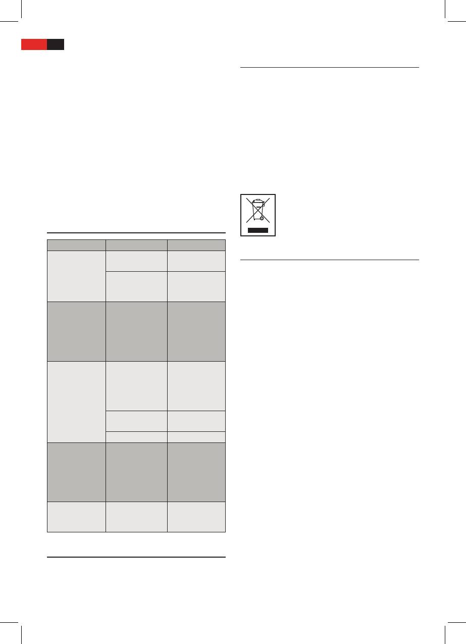
Troubleshooting
Problem Cause Solution
Disposal- Meaning of the “Dustbin” Symbol
Appliance does
No power supply Check the mains
not work.
outlet.
Protect our environment: do not dispose of electrical
Defective electron-
Seek advice from
equipment in the domestic waste.
ics
a dealer or service
Please return any electrical equipment that you will no
centre.
longer use to the collection points provided for their
The POWER LED
The water tank is
Fill the water
disposal.
and one of the
empty.
tank.
MOIST LED´s (LO/
This helps avoid the potential efects of incorrect disposal
MI/HI) are lit, but
on the environment and human health.
no mist is being
This will contribute to the recycling and other forms of
produced.
reutilisation of electrical and electronic equipment.
Not enough mist
Water has col-
Push the top
Information concerning where the equipment can be
is being produced.
lected in the tube
section of the
disposed of can be obtained from your local authority.
underneath the
tube back so that
switch housing
the water cannot
accumulate.
The humidier is
Clean the humidi-
dirty.
er.
The water is dirty. Change the water.
Mist or water
The bottom section
Pull back the
escapes between
of the tube is too
bottom section of
the water tank
short.
the tube so that
and the humidi-
the water tank
er base.
ts securely on
the base.
There is a bad
The water is too
Change the water
smell.
old or dirty.
and clean the
humidier.
Noise development
The workplace-related emission value is less than 70 dB(A).


