AEG ws12-125 451409: инструкция
Раздел: Инструмент, электроинструмент, силовая техника
Тип: Угловая Шлифмашина
Характеристики, спецификации
Инструкция к Угловой Шлифмашиной AEG ws12-125 451409

WS 10-115, WS 10-125,
WS 12-115, WS 12-125, WS 13-125 XE
Original instructions
Instrukcją oryginalną
Originalbetriebsanleitung
Eredeti használati utasítás
Notice originale
Izvirna navodila
Istruzioni originali
Originalne pogonske upute
Manual original
Instrukcijâm oriěinâlvalodâ
Manual original
Originali instrukcija
Oorspronkelijke gebruiksaanwijzing
Algupärane kasutusjuhend
Original brugsanvisning
Оригинальное руководство по
Original bruksanvisning
эксплуатации
Bruksanvisning i original
Оригинално ръководство за
експлоатация
Alkuperäiset ohjeet
Instrucţiuni de folosire originale
Πρωτότυπο οδηγιών χρήσης
Оригинален прирачник за работа
Orijinal işletme talimatı
Оригінал інструкції з експлуатації
Původním návodem k používání
Pôvodný návod na použitie
Technical Data,Safety Instructions, Specied Conditions of Use,
Please read and save
English
14
Mains connection, Maintenance, Symbols
these instructions!
Technische Daten, Sicherheitshinweise, Bestimmungsgemäße Verwendung,
Bitte lesen und
Deutsch
18
Netzanschluss, Wartung, Symbole
aufbewahren!
Caractéristiques techniques, Instructions de sécurité, Utilisation conforme aux
A lire et à conserver
Français
22
prescriptions, Branchement secteur, Entretien, Symboles
soigneusement
Dati tecnici,Norme di sicurezza,Utilizzo conforme, Collegamento alla rete,
Si prega di leggere e
Italiano
26
Manutenzione, Simboli
conservare le istruzioni!
Datos técnicos, Instrucciones de seguridad, Aplicación de acuerdo a la nalidad,
Lea y conserve estas
Español
30
Conexión eléctrica, Mantenimiento, Símbolos
instrucciones por favor!
Características técnicas, Instruções de segurança, Utilização autorizada,
Por favor leia e conserve
Português
34
Ligação à rede, Manutenção, Symbole
em seu poder!
Technische gegevens, Veiligheidsadviezen, Voorgeschreven gebruik van het
Lees en let goed
Nederlands
38
systeem, Netaansluiting,Onderhoud, Symbolen
op deze adviezen!
Tekniske data, Sikkerhedshenvisninger, Tiltænkt formål, Nettilslutning,
Vær venlig at læse
Dansk
42
Vedligeholdelse, Symboler
og Opbevare!
Tekniske data, Spesielle sikkerhetshenvisninger, Formålsmessig bruk,
Vennligst les og oppbevar!
Norsk
46
Nettilkopling, Vedlikehold, Symboler
Tekniska data, Säkerhetsutrustning, Använd maskinen Enligt anvisningarna,
Läs igenom och spara!
Svenska
50
Nätanslutning, Skötsel, Symboler
Tekniset arvot, Turvallisuusohjeet, Tarkoituksenmukainen käyttö,
Lue ja säilytö!
Suomi
54
Verkkoliitäntä, Huolto, Symbolit
Τεχνικά στοιχεία, Ειδικές υποδείξεις ασφάλειας, Χρήση σύμφωνα με το σκοπό
Ελληνικά
58
προορισμού, Μπαταρίες, Χαρακτηριστικά, Συντήρηση, Σύμβολα.
Teknik veriler, Güvenliğiniz için talimatlar, Kullanim, Şebeke bağlantisi,
Lütfen okuyun ve saklayın
Türkçe
63
Bakim, Semboller
Technická data, Speciální bezpečnostní upozornění, Oblast využití,
Po přečtení uschovejte
Česky
67
Připojení na sít, Údržba, Symboly
Technické údaje, Špeciálne bezpčènostné pokyny, Použitie podl’a predpisov,
Prosím prečítať a uschovať!
Slovensky
71
Siet’ová prípojka, Údrzba, Symboly
Dane techniczne, Specjalne zalecenia dotyczące bezpiecze´nstwa,
Należy uważnie przeczytać i
Polski
75
Użytkowanie zgodne z przeznaczeniem, Podłączenie do sieci, Gwarancja, Symbole
zachować do wglądu!
Műszaki adatok, Különleges biztonsági tudnivalók, Rendeltetésszerű használat,
Olvassa el és őrizze meg
Magyar
79
Hálózati csatlakoztatás, Karbantartás, Szimbólumok
Tehnični podatki, Specialni varnostni napotki, Uporaba v skladu z namembnostjo,
Prosimo preberite
Slovensko
83
Omrežni priključek, Vzdrževanje, Simboli
in shranite!
Tehnički podaci, Specijalne sigurnosne upute, Propisna upotreba,
Molimo pročitati i sačuvati
Hrvatski
87
Priključak na mrežu, Održavanje, Simboli
Tehniskie dati, Speciālie drošības noteikumi, Noteikumiem atbilstošs izmantojums,
Pielikums lietošanas pamācībai
Latviski
91
Tīkla pieslēgums, Apkope, Simboli
Techniniai duomenys, Ypatingos saugumo nuorodos, Naudojimas pagal paskirti,
Prašome perskaityti
Lietuviškai
95
Elektros tinklo jungtis, Techninis aptarnavimas, Simboliai
ir neišmesti!
Tehnilised andmed, Spetsiaalsed turvajuhised, Kasutamine vastavalt otstarbele,
Palun lugege läbi ja hoidke alal!
Eesti
99
Võrku ühendamine, Hooldus, Sümbolid
Òåõíè÷åñêèå äàííûå, Ðåêîìåíäàöèè ïî òåõíèêå áåçîïàñíîñòè,
Пожалуйста прочтите и
Pусский
103
Èñïîëüçî- âàíèå, Îáñëóæèâàíèå, Ñèìâîëû
сохраните эту инструкцию.
Òåõíè÷åñêè äàííè, Ñïåöèàëíè óêàçàíèÿ çà áåçîïàñíîñò, Èçïîëçâàíå ïî
Моля прочетете и запазете!
Български
108
ïðåäíàçíà÷åíèå, Ñâúðçâàíå êúì ìðåæàòà, Ïîääðúæêà, Ñèìâîëè
Date tehnice, Instrucţiuni de securitate, Condiţii de utilizare specifcate,
Va rugăm citiţi şi păstraţi
Română
112
Acumulatori, Intreţinere, Simboluri
aceste instrucţiuni
Òåõíè÷êè Ïîäàòîöè, Óïàòñòâî Çà Óïîòðåáà, Ñïåöèôèöèðàíè Óñëîâè
Ве мoлиме прочитаjте го и
Мaкeдohcки
116
Íà Óïîòðåáà, БАТЕРИИ, Îäðæóâàњå, Ñèìáîëè
чувајте го ова упатство!
Технічні характеристики, Вказівки З Техніки Безпеки, Використання за призначенням,
Прочитайте та збережіть
Українська
120
Підключення до мережі, Обслуговування, Символи
цю інструкцію.
127
VII
TIP
I II III
IV
V
VI
Accessory
VIII
Zubehör
Accessoires
Accessorio
Accessorio Acessório
Toebehoren
Tilbehør
Tilbehør
Tillbehör
Lisälaite
Aksesuar
Příslušenství
Príslušenstv
Azokat a tartozékokat
Oprema
Piederumi
IX
Priedas
Tarvikud
Äîïîëíèòåëü
Accesoriu
A B
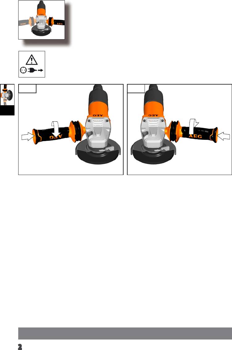
I
2
II
1.
2.
4.3.
2
1
3
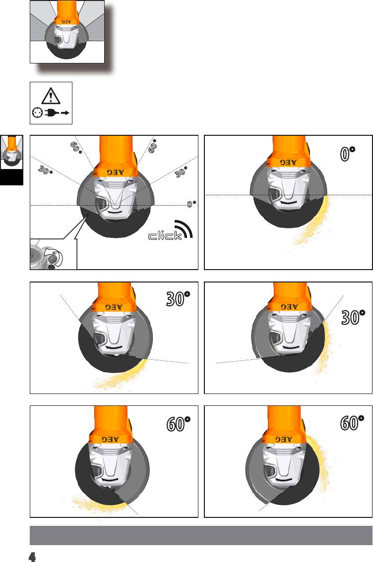
60
°
°
60
0°
30
°
°
30
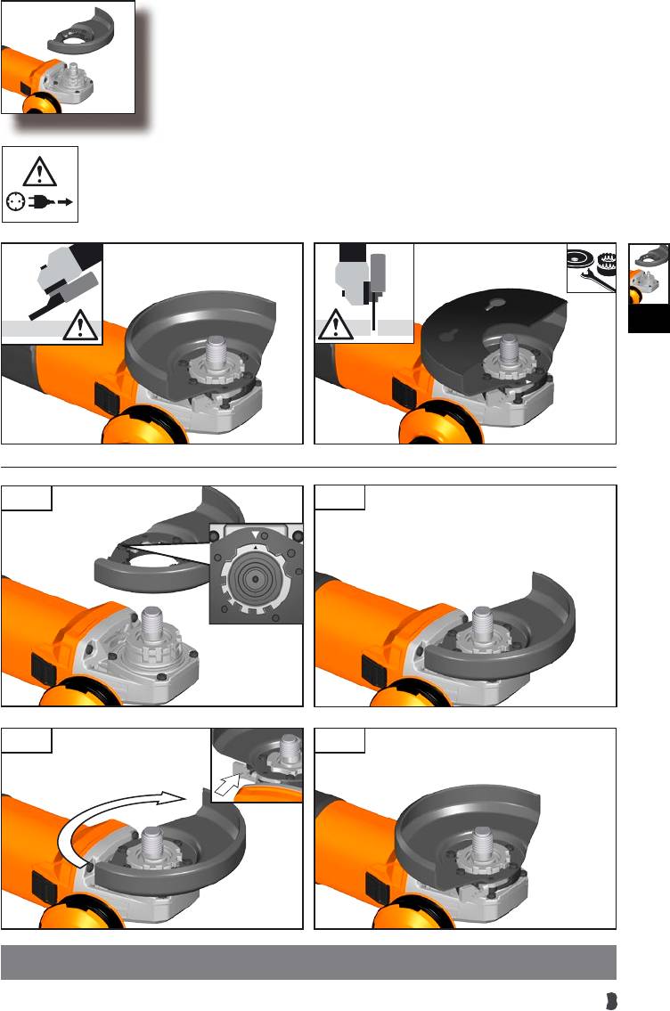
III
0
°
30°
30°
60°
60°
4
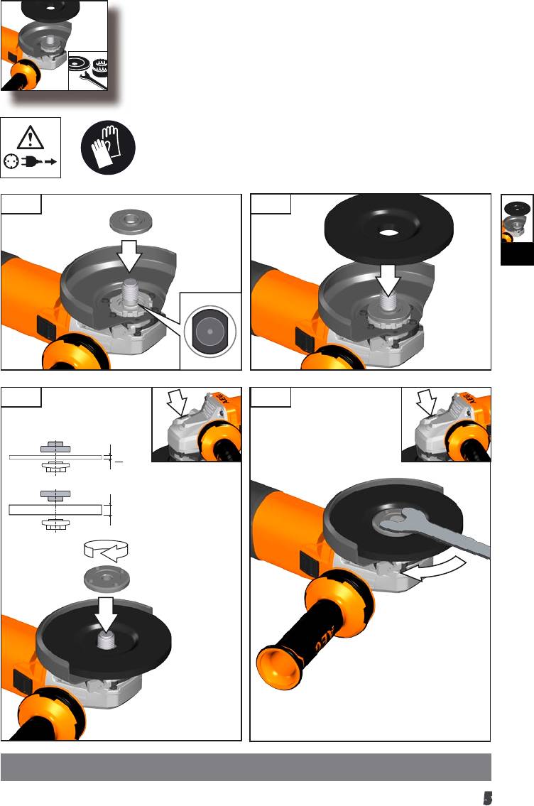
1.
2.
IV
3.
4.
< 6 mm
> 6 mm
5
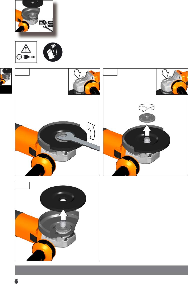
2.1.
IV
3.
6
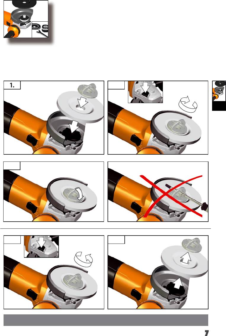
WS ...-... X...
1. 2.
IV
3.
1. 2.
7
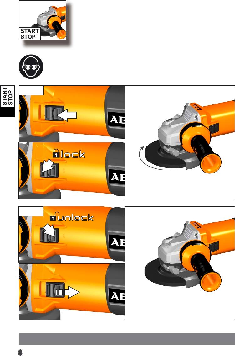
Start
V
Stop
8
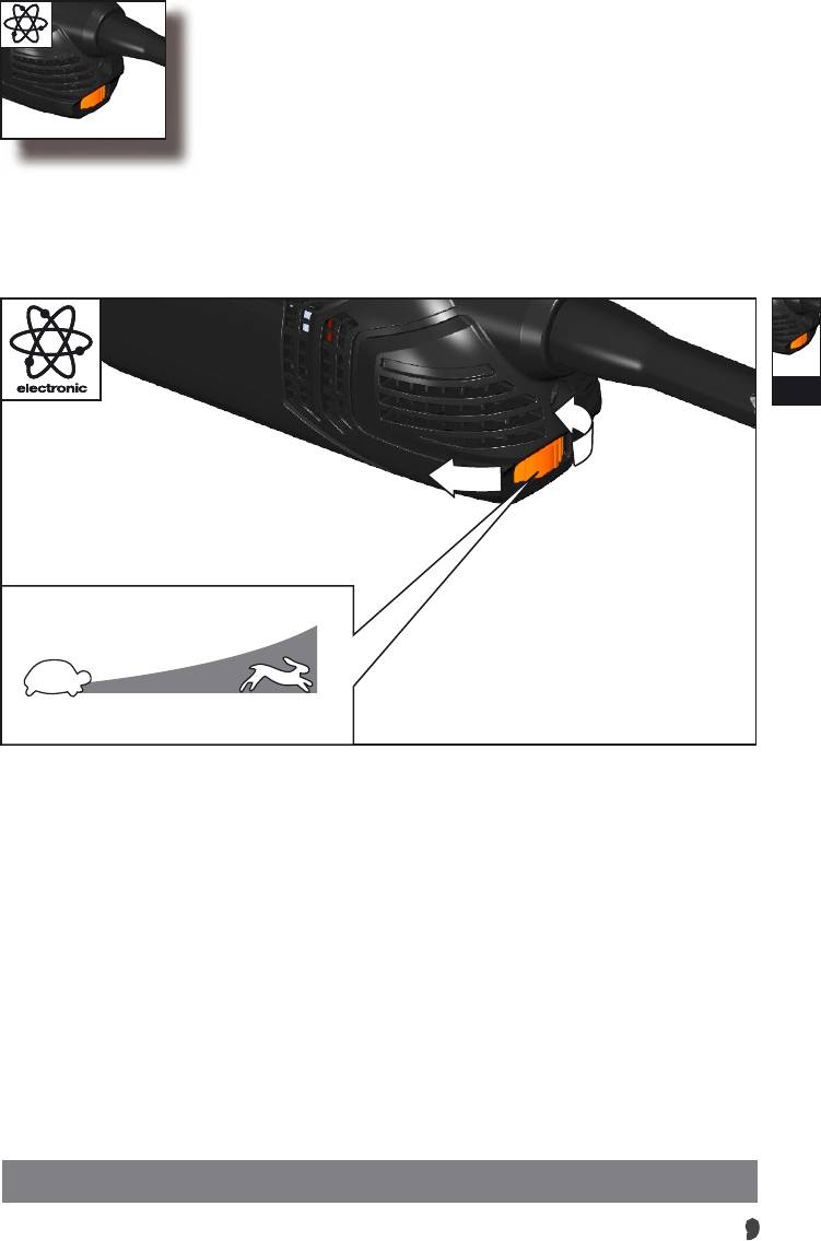
WS ...-... E...
VI
C
A...B...C...D...E
9
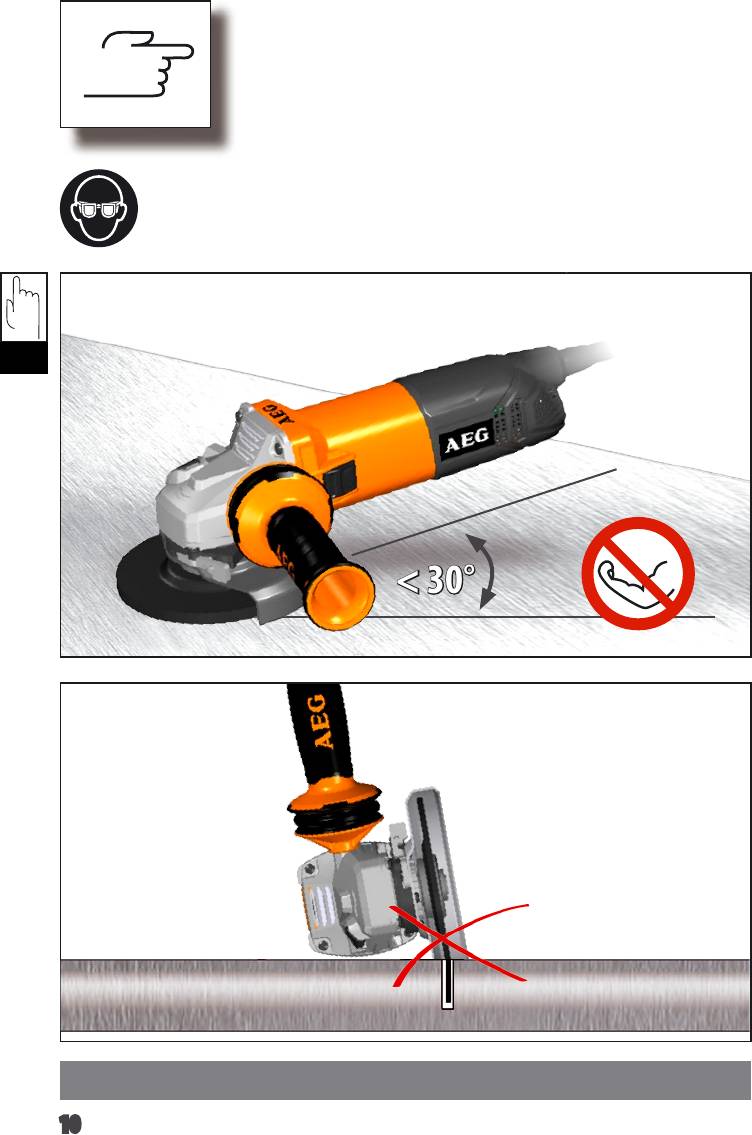
TIP
TIP
< 30°
10
TIP
VII

Accessory
Tilbehør
Príslušenstv
Aksessuaarid
Zubehör
Tilbehør
Äîïîëíèòåëü
Accessoires
Tillbehör
Tartozékokat
Accessorio
Lisälaite
Oprema
Accesoriu
Accessorio
Piederumi
Acessório
Aksesuar
Prieda
Toebehoren
Tarvikud
1. 2.
VIII
1.
2.
11
Accessory
Tilbehør
Príslušenstv
Aksessuaarid
Zubehör
Tilbehør
Äîïîëíèòåëü
Accessoires
Tillbehör
Tartozékokat
Accessorio
Lisälaite
Oprema
Accesoriu
Accessorio
Piederumi
Acessório
Aksesuar
Prieda
Toebehoren
Tarvikud
1.
2.
VIII
3.
12
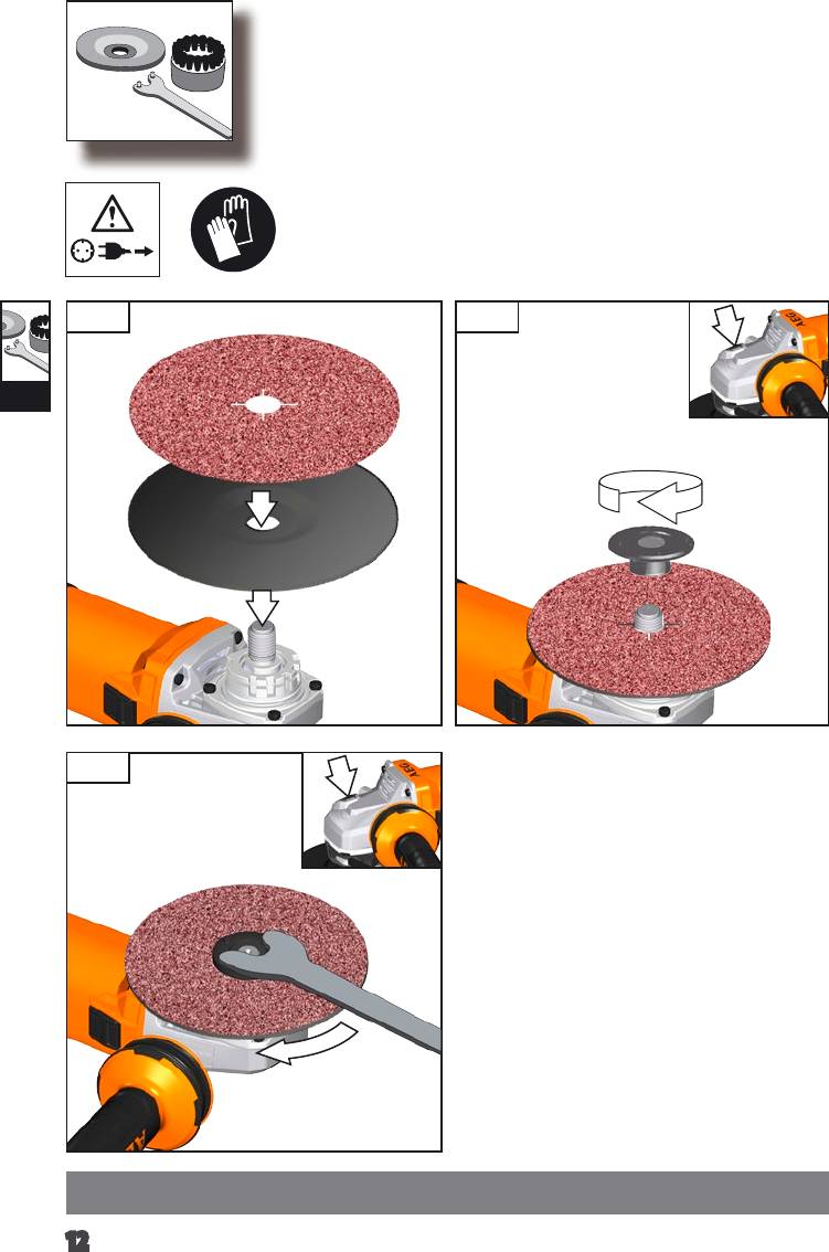
Accessory
Tilbehør
Príslušenstv
Aksessuaarid
Zubehör
Tilbehør
Äîïîëíèòåëü
Accessoires
Tillbehör
Tartozékokat
Accessorio
Lisälaite
Oprema
Accesoriu
Accessorio
Piederumi
Acessório
Aksesuar
Prieda
Toebehoren
Tarvikud
2.1.
VIII
3.
13
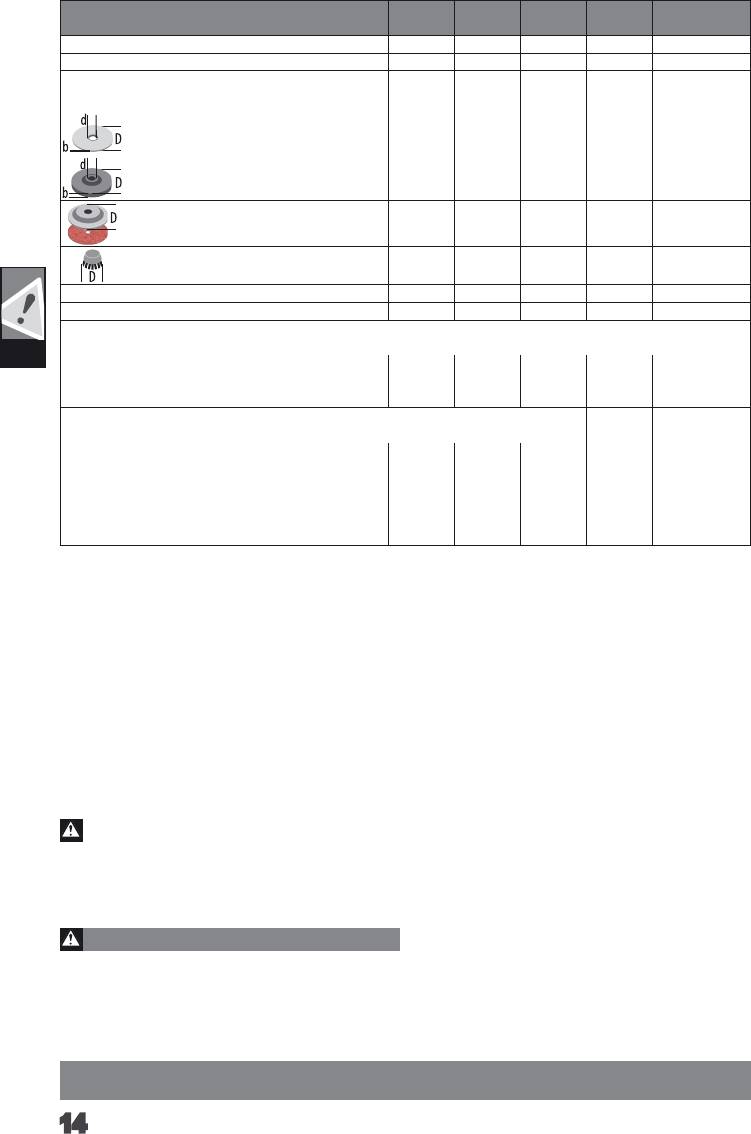
TECHNICAL DATA
WS 10-115 WS 10-125 WS 12-115 WS 12-125 WS 13-125 XE
Angle Grinder
Rated input 1000 W 1000 W 1200 W 1200 W 1300 W
-1
-1
-1
-1
-1
Rated speed 11500 min
11500 min
11500 min
11500 min
2800 - 11500 min
D= Grinding disk diameter max.
115 mm
125 mm
115 mm
125 mm
125 mm
22,2 mm
22,2 mm
22,2 mm
22,2 mm
22,2 mm
d= Grinding disk hole diameter
b= Cutting disk thickness min. / max.
1/3 mm 1/3 mm 1/3 mm 1/3 mm 1/3 mm
b= Grinding disk thickness max. 6 mm 6 mm 6 mm 6 mm 6 mm
D= Grinding surface diameter max. 115 mm 125 mm 115 mm 125 mm 125 mm
D= Wiring brush diameter max. 75 mm 75 mm 75 mm 75 mm 75 mm
Thread of work spindle M 14 M 14 M 14 M 14 M 14
Weight according EPTA-Procedure 01/2003 2,3 kg 2,3 kg 2,4 kg 2,4 kg 2,4 kg
Noise information
Measured values determined according to EN 60745. Typically, the A-weighted noise levels of the tool are:
GB
Sound pressure level (Uncertainty K=3dB(A)) 87,1 dB (A) 87,1 dB (A) 87,1 dB (A) 87,1 dB (A) 90,1 dB (A)
Sound power level (Uncertainty K=3dB(A)) 98,1 dB (A) 98,1 dB (A) 98,1 dB (A) 98,1 dB (A) 101,1 dB (A)
Wear ear protectors!
Vibration information
Vibration total values (triaxial vector sum) determined according to EN 60745
Surface grinding:
2
2
2
2
2
Vibration emission value a
6,2 m/s
6,2 m/s
6,2 m/s
6,2 m/s
8,0 m/s
h,SG
2
2
2
2
2
Uncertainty K=
1,5 m/s
1,5 m/s
1,5 m/s
1,5 m/s
1,5 m/s
Disk sanding:
2
2
2
2
2
Vibration emission value a
6,0 m/s
6,0 m/s
6,0 m/s
6,0 m/s
7,5 m/s
h,DS
2
2
2
2
2
Uncertainty K=
1,5 m/s
1,5 m/s
1,5 m/s
1,5 m/s
1,5 m/s
For other applications, e.g. Abrasive Cutting-O Operations or Wire Brushing other vibration values could occur.
WARNING!
The vibration emission level given in this information sheet has been measured in accordance with a standardised test given in EN 60745
and may be used to compare one tool with another. It may be used for a preliminary assessment of exposure.
The declared vibration emission level represents the main applications of the tool. However if the tool is used for dierent applications,
with dierent accessories or poorly maintained, the vibration emission may dier. This may signicantly increase the exposure level over
the total working period.
An estimation of the level of exposure to vibration should also take into account the times when the tool is switched o or when it is
running but not actually doing the job. This may signicantly reduce the exposure level over the total working period.
Identify additional safety measures to protect the operator from the eects of vibration such as: maintain the tool and the accessories,
keep the hands warm, organisation of work patterns.
this power tool. Failure to follow all instructions listed below may
WARNING!
result in electric shock, re and/or serious injury.
Read all safety warnings and all instructions. Failure to
b) Operations such as polishing are not recommended
follow the warnings and instructions may result in electric shock,
to be performed with this power tool.Operations for which
re and/or serious injury.
the power tool was not designed may create a hazard and cause
Save all warnings and instructions for future reference.
personal injury.
ANGLE GRINDER SAFETY WARNINGS
c) Do not use accessories which are not specically
designed and recommended by the tool manufacturer. Just
Safety Warnings Common for Grinding, Sanding, Wire
because the accessory can be attached to your power tool, it does
Brushing or Abrasive Cutting-O Operations:
not assure safe operation.
a) This power tool is intended to function as a grinder,
d) The rated speed of the accessory must be at least equal
sander, wire brush or cut-o tool. Read all safety warnings,
to the maximum speed marked on the power tool. Accesso-
instructions, illustrations and specications provided with
ries running faster than their rated speed can break and y apart.
English
14

e) The outside diameter and the thickness of your
causes the uncontrolled power tool to be forced in the direction
accessory must be within the capacity rating of your power
opposite of the accessory’s rotation at the point of the binding.
tool. Incorrectly sized accessories cannot be adequately guarded
For example, if an abrasive wheel is snagged or pinched by the
or controlled.
workpiece, the edge of the wheel that is entering into the pinch
f) Threaded mounting of accessories must match the grin-
point can dig into the surface of the material causing the wheel
to climb out or kick out. The wheel may either jump toward or
der spindle thread. For accessories mounted by anges, the
away from the operator, depending on direction of the wheel’s
arbour hole of the accessory must t the locating diameter
movement at the point of pinching. Abrasive wheels may also break
of the ange. Accessories that do not match the mounting hard-
under these conditions.
ware of the power tool will run out of balance, vibrate excessively
and may cause loss of control.
Kickback is the result of power tool misuse and/or incorrect opera-
ting procedures or conditions and can be avoided by taking proper
g) Do not use a damaged accessory. Before each use inspect
precautions as given below.
the accessory such as abrasive wheels for chips and cracks,
backing pad for cracks, tear or excess wear, wire brush for
a) Maintain a rm grip on the power tool and position your
loose or cracked wires. If power tool or accessory is dropped,
body and arm to allow you to resist kickback forces. Always
inspect for damage or install an undamaged accessory. After
use auxiliary handle, if provided, for maximum control over
inspecting and installing an accessory, position yourself and
kickback or torque reaction during start-up. The operator can
control torque reactions or kickback forces, if proper precautions
bystanders away from the plane of the rotating accessory
are taken.
and run the power tool at maximum no-load speed for one
minute. Damaged accessories will normally break apart during this
b) Never place your hand near the rotating accessory.
test time.
Accessory may kickback over your hand.
h) Wear personal protective equipment. Depending on
c) Do not position your body in the area where power tool
GB
application, use face shield, safety goggles or safety glasses.
will move if kickback occurs. Kickback will propel the tool in
As appropriate, wear dust mask, hearing protectors, gloves
direction opposite to the wheel’s movement at the point of snagging.
and shop apron capable of stopping small abrasive or
d) Use special care when working corners, sharp edges etc.
workpiece fragments. The eye protection must be capable of
Avoid bouncing and snagging the accessory. Corners, sharp
stopping ying debris generated by various operations. The dust
edges or bouncing have a tendency to snag the rotating accessory
mask or respirator must be capable of ltrating particles generated
and cause loss of control or kickback.
by your operation. Prolonged exposure to high intensity noise may
e) Do not attach a saw chain woodcarving blade or toothed
cause hearing loss.
saw blade. Such blades create frequent kickback and loss of control.
i) Keep bystanders a safe distance away from work area.
Anyone entering the work area must wear personal protec-
Safety Warnings Specic for Grinding and Abrasive Cutting-
tive equipment. Fragments of workpiece or of a broken accessory
O Operations:
may y away and cause injury beyond immediate area of operation.
a) Use only wheel types that are recommended for your
j) Hold the power tool by insulated gripping surfaces only,
power tool and the specic guard designed for the selected
when performing an operation where the cutting accessory
wheel. Wheels for which the power tool was not designed cannot be
may contact hidden wiring or its own cord. Cutting accessory
adequately guarded and are unsafe.
contacting a „live“ wire may make exposed metal parts of the power
b) The guard must be securely attached to the power tool
tool „live“ and could give the operator an electric shock.
and positioned for maximum safety, so the least amount
k) Position the cord clear of the spinning accessory. If you lose
of wheel is exposed towards the operator. The guard helps
control, the cord may be cut or snagged and your hand or arm may be
to protect the operator from broken wheel fragments, accidental
pulled into the spinning wheel.
contact with wheel and sparks that could ignite clothing.
l) Never lay the power tool down until the accessory has
c) Wheels must be used only for recommended applications.
come to a complete stop. The spinning accessory may grab the
For example: do not grind with the side of cut-o wheel. Abra
-
surface and pull the power tool out of your control.
sive cut-o wheels are intended for peripheral grinding, side forces
m) Do not run the power tool while carrying it at your side.
a
pplied to these wheels may cause them to shatter.
Accidental contact with the spinning accessory could snag your
d) Always use undamaged wheel anges that are of correct
clothing, pulling the accessory into your body.
size and shape for your selected wheel. Proper wheel anges
n) Regularly clean the power tool’s air vents. The motor’s fan
support the wheel thus reducing the possibility of wheel breakage.
will draw the dust inside the housing and excessive accumulation of
Flanges for cut-o wheels may be dierent from grinding wheel
powdered metal may cause electrical hazards.
anges.
o) Do not operate the power tool near ammable materials.
e) Do not use worn down wheels from larger power tools.
Sparks could ignite these materials.
Wheel intended for larger power tool is not suitable for the higher
p) Do not use accessories that require liquid coolants. Using
speed of a smaller tool and may burst.
water or other liquid coolants may result in electrocution or shock.
Additional Safety Warnings Specic for Abrasive Cutting-O
Kickback and Related Warnings
Operations:
Kickback is a sudden reaction to a pinched or snagged rotating
a) Do not “jam” the cut-o wheel or apply excessive pressure.
wheel, backing pad, brush or any other accessory. Pinching or snag-
Do not attempt to make an excessive depth of cut. Overstressing
ging causes rapid stalling of the rotating accessory which in turn
the wheel increases the loading and susceptibility to twisting or
English
15

binding of the wheel in the cut and the possibility of kickback or wheel
MAINS CONNECTION
breakage.
Connect only to single-phase AC system voltage as indicated on
b) Do not position your body in line with and behind the
the rating plate. It is also possible to connect to sockets without an
rotating wheel. When the wheel, at the point of operation, is moving
earthing contact as the design conforms to safety class II.
away from your body, the possible kickback may propel the spinning
Appliances used at many dierent locations including wet room
wheel and the power tool directly at you.
and open air must be connected via a residual current device (FI,
c) When wheel is binding or when interrupting a cut for any
RCD, PRCD) of 30mA or less.
reason, switch o the power tool and hold the power tool
Only plug-in when machine is switched o.
motionless until the wheel comes to a complete stop. Never
Do not let any metal parts enter the airing slots - danger of short
attempt to remove the cut-o wheel from the cut while the
circuit!
wheel is in motion otherwise kickback may occur. Investigate
Inrush currents cause short-time voltage drops. Under unfavoura-
and take corrective action to eliminate the cause of wheel binding.
ble power supply conditions, other equipment may be aected. If
d) Do not restart the cutting operation in the workpiece. Let
the system impedance of the power supply is lower than 0,2 Ohm,
the wheel reach full speed and carefully re-enter the cut. The
disturbances are unlikely to occur.
wheel may bind, walk up or kickback if the power tool is restarted in
the workpiece.
SPECIFIED CONDITIONS OF USE
e) Support panels or any oversized workpiece to minimize the
The angle grinder is intended for grinding and cutting metal, stone
risk of wheel pinching and kickback. Large workpieces tend to sag
and ceramicmaterials as well as sanding and wire brushing.
under their own weight. Supports must be placed under the workpiece
Use the cutting guard from the accessories range for cutting
near the line of cut and near the edge of the workpiece on both sides
application.
GB
of the wheel.
Please refer to the instructions supplied by the accessory
f) Use extra caution when making a “pocket cut” into existing
manufacturer.
walls or other blind areas. The protruding wheel may cut gas or
The machine is suitable only for working without water.
water pipes, electrical wiring or objects that can cause kickback.
WORKING INSTRUCTIONS
Safety Warnings Specic for Sanding Operations:
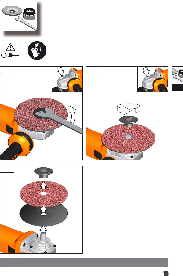
For accessories intended to be tted with threaded hole wheel,
a) Do not use excessively oversized sanding disc paper.
ensure that the thread in the wheel is long enough to accept the
Follow manufacturers recommendations, when selecting
spindle length.
sanding paper. Larger sanding paper extending beyond the
Always use and store the cutting and grinding disks according to
sanding pad presents a laceration hazard and may cause snagging,
the manufacturer‘s instructions.
tearing of the disc or kickback.
Always use the correct guard for cutting and grinding.
Safety Warnings Specic for Wire Brushing Operations:
The grinding surface of the centre depressed disks must be moun-
ted min. 2 mm below the plane of the guard lip.
a) Be aware that wire bristles are thrown by the brush
The adjusting nut must be tightened before starting to work with
even during ordinary operation. Do not overstress the wires
the machine.
by applying excessive load to the brush. The wire bristles can
Always use the auxiliary handle.
easily penetrate light clothing and/or skin.
The workpiece must be xed if it is not heavy enough to be steady.
b) If the use of a guard is recommended for wire brushing,
Never move the workpiece towards the rotating disk by hand.
do not allow any interference of the wire wheel or brush
The ange nut must be securely tightened before the machine is
with the guard. Wire wheel or brush may expand in diameter due
started.
to work load and centrifugal forces.
If the tool is not securely tightened with the ange nut, it is pos-
Additional Safety and Working Instructions
sible that the tool will lose the required clamping force when it is
decelerated.
When grinding metal, ying sparks are produced. Take care that
In the event that a power failure occurs whilst the machine is
no persons are endangered. Because of the danger of re, no
operating, the brake function will be inoperative.
combustible materials should be located in the vicinity (spark ight
zone). Do not use dust extraction.
ELECTRONICS
Avoid ying sparks and sanding dust hit your body.
WS 13-125 XE: The built-in electronic will keep a constant speed
even under increased load. In case of overload, the rotational speed
Never reach into the danger area of the machine when it is running.
is being reduced until machine stops.
Immediately switch o the machine in case of considerable vibra-
Electronic smooth start for save use prevents jerky run-up of the
tions or if other malfunctions occur. Check the machine in order to
machine.
nd out the cause.
Under extreme conditions (e.g. smooth-grinding metals with
MAINTENANCE
the arbour and vulcanized bre grinding disk), signicant
The ventilation slots of the machine must be kept clear at all times.
contamination can build up on the inside of the angle grinder. For
safety reasons, in such conditions a ground fault interrupter must
If the supply cord of this power tool is damaged, it must be
be connected in series. If the ground fault interrupter trips the
replaced by a specially prepared cord available through the service
machine must be sent for service.
organization.
Chips and splinters must not be removed while the machine is
running.
English
16
Use only AEG accessories and spare parts. Should components need to
be replaced which have not been described, please contact one of our
AEG service agents (see our list of guarantee/service addresses).
If needed, an exploded view of the tool can be ordered. Please state
the Article No. as well as the machine type printed on the label
and order the drawing at your local service agents or directly at:
Techtronic Industries GmbH, Max-Eyth-Straße10, 71364Winnen-
den, Germany.
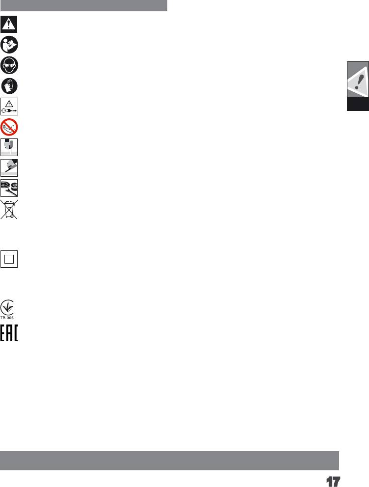
SYMBOLS
CAUTION! WARNING! DANGER!
Please read the instructions carefully before starting the
machine.
Always wear goggles when using the machine.
Wear gloves!
Always disconnect the plug from the socket before
GB
carrying out any work on the machine.
Do not use force.
Only for cutting work.
Only for grinding.
Accessory - Not included in standard equipment, availa-
ble as an accessory.
Do not dispose of electric tools together with household
waste material. Electric tools and electronic equipment
that have reached the end of their life must be collected
separately and returned to an environmentally compatible
recycling facility. Check with your local authority or retailer
for recycling advice and collection point.
Class II tool. Tool in which protection against electric
shock does not rely on basic insulation only, but in which
additional safety precautions, such as double insulation
or reinforced insulation, are provided. There being
no provision for protective earthing or reliance upon
installation conditions.
UkrSEPRO Conformity Mark
EurAsian Conformity Mark
English
17
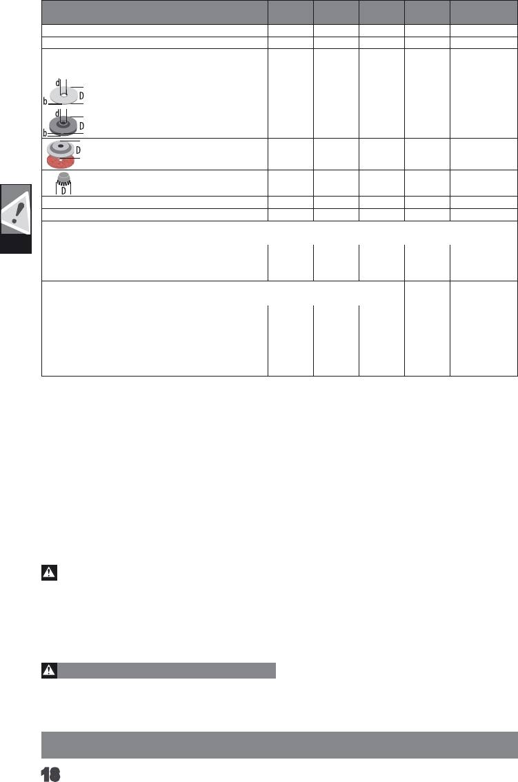
TECHNISCHE DATEN
WS 10-115 WS 10-125 WS 12-115 WS 12-125 WS 13-125 XE
Winkelschleifer
Nennaufnahmeleistung 1000 W 1000 W 1200 W 1200 W 1300 W
-1
-1
-1
-1
-1
Nenndrehzahl 11500 min
11500 min
11500 min
11500 min
2800 - 11500 min
D= Schleifscheibendurchmesser max.
115 mm
125 mm
115 mm
125 mm
125 mm
22,2 mm
22,2 mm
22,2 mm
22,2 mm
22,2 mm
d= Bohrungsdurchmesser
b= Trennscheibendicke min. / max.
1/3 mm 1/3 mm 1/3 mm 1/3 mm 1/3 mm
b= Schleifscheibendicke max. 6 mm 6 mm 6 mm 6 mm 6 mm
D= Schleiächendurchmesser max. 115 mm 125 mm 115 mm 125 mm 125 mm
D= Topfbürstendurchmesser max. 75 mm 75 mm 75 mm 75 mm 75 mm
Spindelgewinde M 14 M 14 M 14 M 14 M 14
Gewicht nach EPTA-Prozedur 01/2003 2,3 kg 2,3 kg 2,4 kg 2,4 kg 2,4 kg
Geräuschinformation
Messwerte ermittelt entsprechend EN 60745. Der A-bewertete Geräuschpegel des Gerätes beträgt typischerweise:
D
Schalldruckpegel (Unsicherheit K=3dB(A)) 87,1 dB (A) 87,1 dB (A) 87,1 dB (A) 87,1 dB (A) 90,1 dB (A)
Schallleistungspegel (Unsicherheit K=3dB(A)) 98,1 dB (A) 98,1 dB (A) 98,1 dB (A) 98,1 dB (A) 101,1 dB (A)
Gehörschutz tragen!
Vibrationsinformationen
Schwingungsgesamtwerte (Vektorsumme dreier Richtungen) ermittelt entsprechend EN 60745.
Oberächenschleifen:
2
2
2
2
2
Schwingungsemissionswert a
6,2 m/s
6,2 m/s
6,2 m/s
6,2 m/s
8,0 m/s
h,SG
2
2
2
2
2
Unsicherheit K=
1,5 m/s
1,5 m/s
1,5 m/s
1,5 m/s
1,5 m/s
Schleifen mit Schleifblatt:
2
2
2
2
2
Schwingungsemissionswert a
6,0 m/s
6,0 m/s
6,0 m/s
6,0 m/s
7,5 m/s
h,DS
2
2
2
2
2
Unsicherheit K=
1,5 m/s
1,5 m/s
1,5 m/s
1,5 m/s
1,5 m/s
Bei anderen Anwendungen, wie z.B. Trennschleifen oder Schleifen mit der Stahldrahtbürste können sich andere Vibrationswerte ergeben!
WARNUNG!
Der in diesen Anweisungen angegebene Schwingungspegel ist entsprechend einem in EN 60745 genormten Messverfahren gemessen
worden und kann für den Vergleich von Elektrowerkzeugen miteinander verwendet werden. Er eignet sich auch für eine vorläuge
Einschätzung der Schwingungsbelastung.
Der angegebene Schwingungspegel repräsentiert die hauptsächlichen Anwendungen des Elektrowerkzeugs. Wenn allerdings das
Elektrowerkzeug für andere Anwendungen, mit abweichenden Einsatzwerkzeugen oder ungenügender Wartung eingesetzt wird, kann
der Schwingungspegel abweichen. Dies kann die Schwingungsbelastung über den gesamten Arbeitszeitraum deutlich erhöhen.
Für eine genaue Abschätzung der Schwingungsbelastung sollten auch die Zeiten berücksichtigt werden, in denen das Gerät abgeschaltet
ist oder zwar läuft, aber nicht tatsächlich im Einsatz ist. Dies kann die Schwingungsbelastung über den gesamten Arbeitszeitraum
deutlich reduzieren.
Legen Sie zusätzliche Sicherheitsmaßnahmen zum Schutz des Bedieners vor der Wirkung von Schwingungen fest wie zum Beispiel:
Wartung von Elektrowerkzeug und Einsatzwerkzeugen, Warmhalten der Hände, Organisation der Arbeitsabläufe.
a) Dieses Elektrowerkzeug ist zu verwenden als Schleifer,
WARNUNG!
Sandpapierschleifer, Drahtbürste und Trennschleifma-
Lesen Sie alle Sicherheitshinweise und Anweisungen.
schine. Beachten Sie alle Sicherheitshinweise, Anwei-
Versäumnisse bei der Einhaltung der Sicherheitshinweise und
sungen, Darstellungen und Daten, die Sie mit dem Gerät
Anweisungen können elektrischen Schlag, Brand und/oder schwere
erhalten. Wenn Sie die folgenden Anweisungen nicht beachten,
Verletzungen verursachen.
kann es zu elektrischem Schlag, Feuer und/oder schweren Verlet-
Bewahren Sie alle Sicherheitshinweise und Anweisungen
zungen kommen.
für die Zukunft auf.
b) Dieses Elektrowerkzeug ist nicht geeignet zum Polieren.
Verwendungen, für die das Elektrowerkzeug nicht vorgesehen ist,
SICHERHEITSHINWEISE FÜR WINKELSCHLEIFER
können Gefährdungen und Verletzungen verursachen.
Gemeinsame Sicherheitshinweise zum Schleifen,
c) Verwenden Sie kein Zubehör, das vom Hersteller
Sandpapierschleifen, Arbeiten mit Drahtbürsten und
nicht speziell für dieses Elektrowerkzeug vorgesehen
Trennschleifen:
und empfohlen wurde. Nur weil Sie das Zubehör an Ihrem
Deutsch
18
