AEG voxtel r200: инструкция
Раздел: Сети, связь, телекоммуникации, интернет, безопасность
Тип: Радиостанция
Характеристики, спецификации
Инструкция к Радиостанции AEG voxtel r200
USER GUIDE
UK DE FR NL IT SW PL GR CZ
PMR
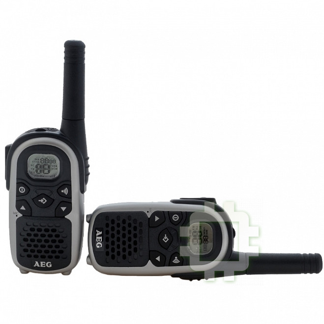
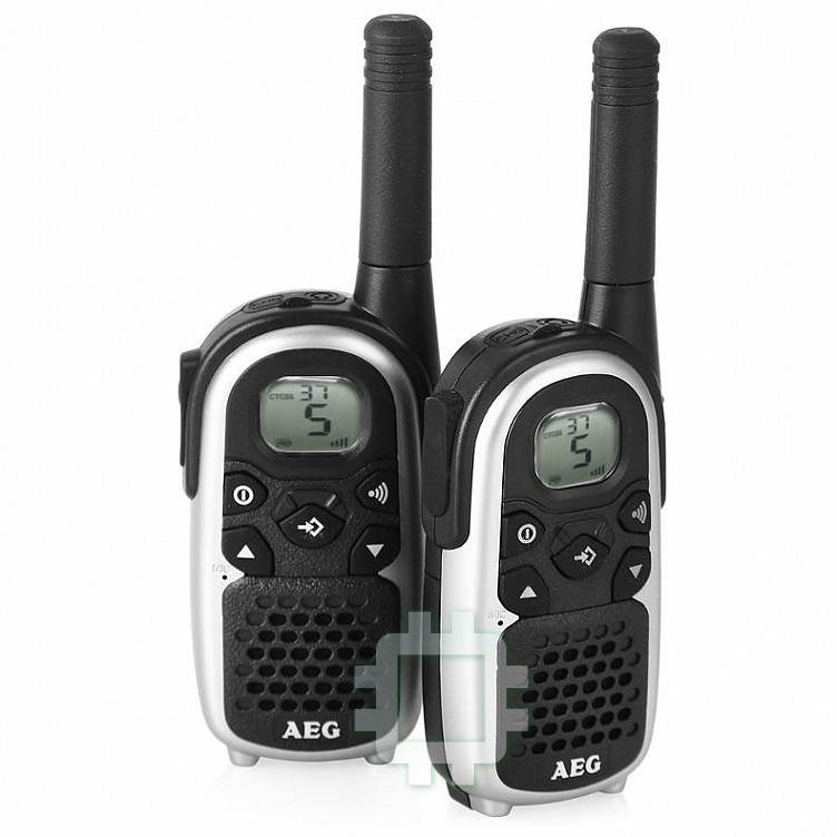
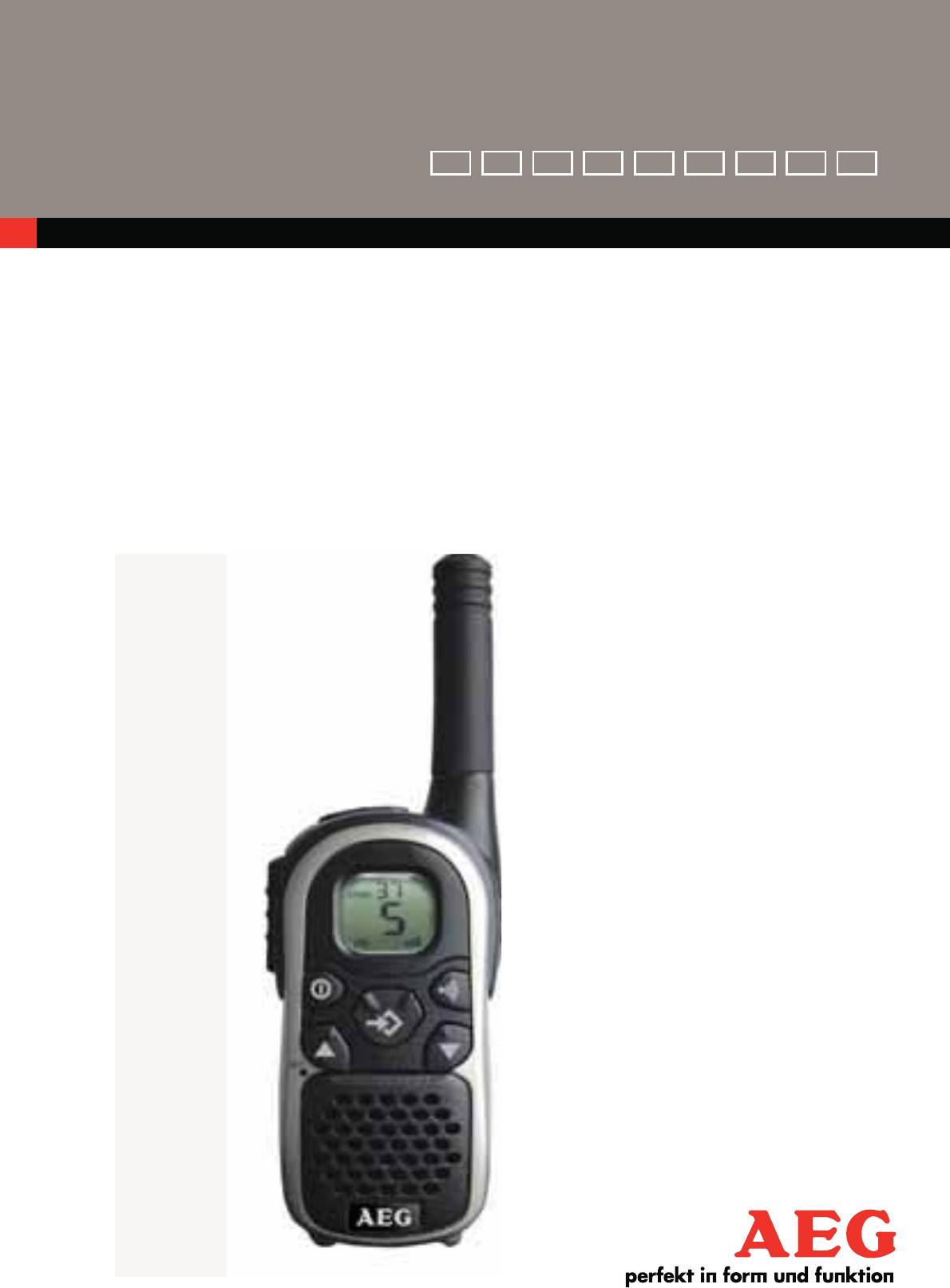
Voxtel R200/R210/R220
V2
2
P1
P2
DCS
CTCSS
VOX
SC
DCM
TX
10
RX
9
8
1
7
2
3
4
6
5
P3
P5P4
AEG
3
1 BECAUSE WE CARE
Thank you for purchasing this product. This product has been designed
UK
and assembled with utmost care for you and the environment. This is
why we supply this product with a quick installation guide to reduce the
number of paper (pages) and therefor save trees to be cut for making
this paper. Thank you for supporting us to protect our environment.
2 GETTING TO KNOW YOUR PMR
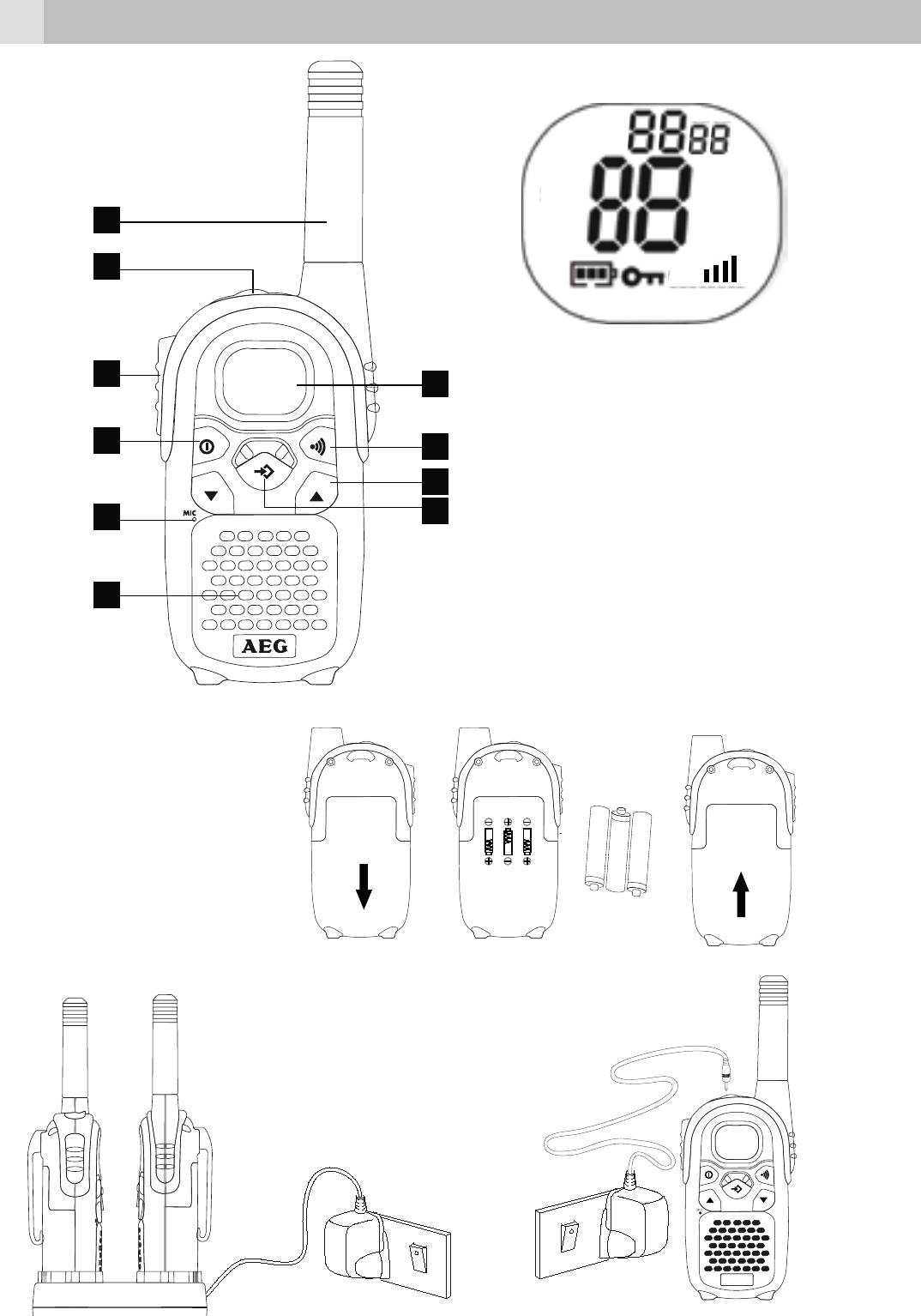
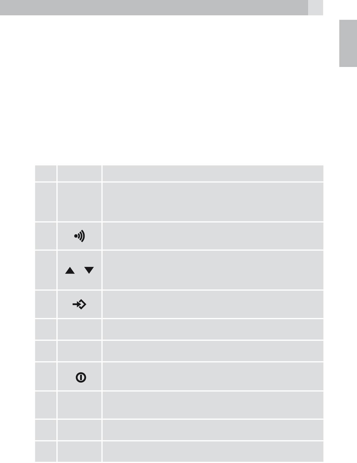
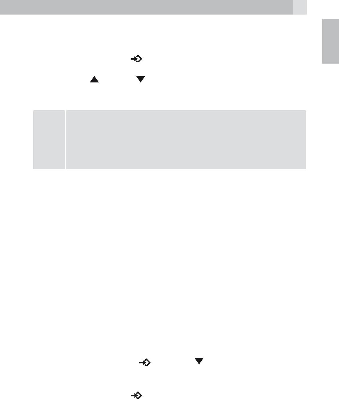
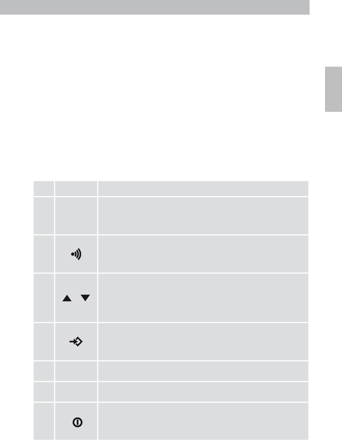
2.1 Handset overview (see P1)
# Meaning
LCD screen
1
tDisplays the current channel selection and other
radio symbols.
Call button
2
tPress to send ringing tone to other PMR units.
Up / down buttons
3
/
tPress to change channels, volume and to select
settings during programming.
Menu button
4
tPress to switch between modes.
Speaker
5
Microphone
6 MIC
Power button
7
tPress and hold to turn the unit on or off.
PTT (push to talk) button
8 PTT
tPress and hold to transmit.
Microphone/earphone/charge jack
9
Antenna
10
4
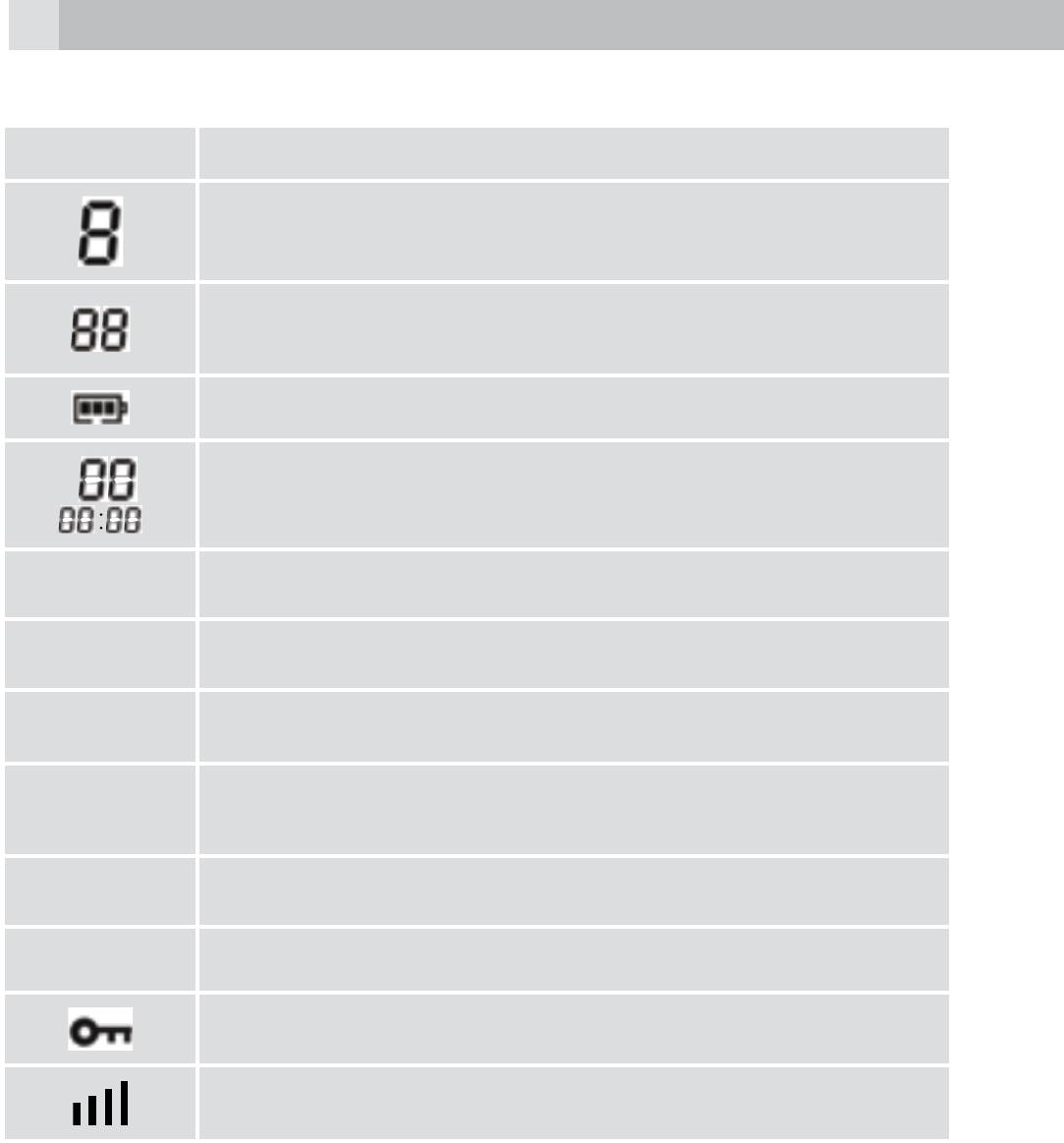
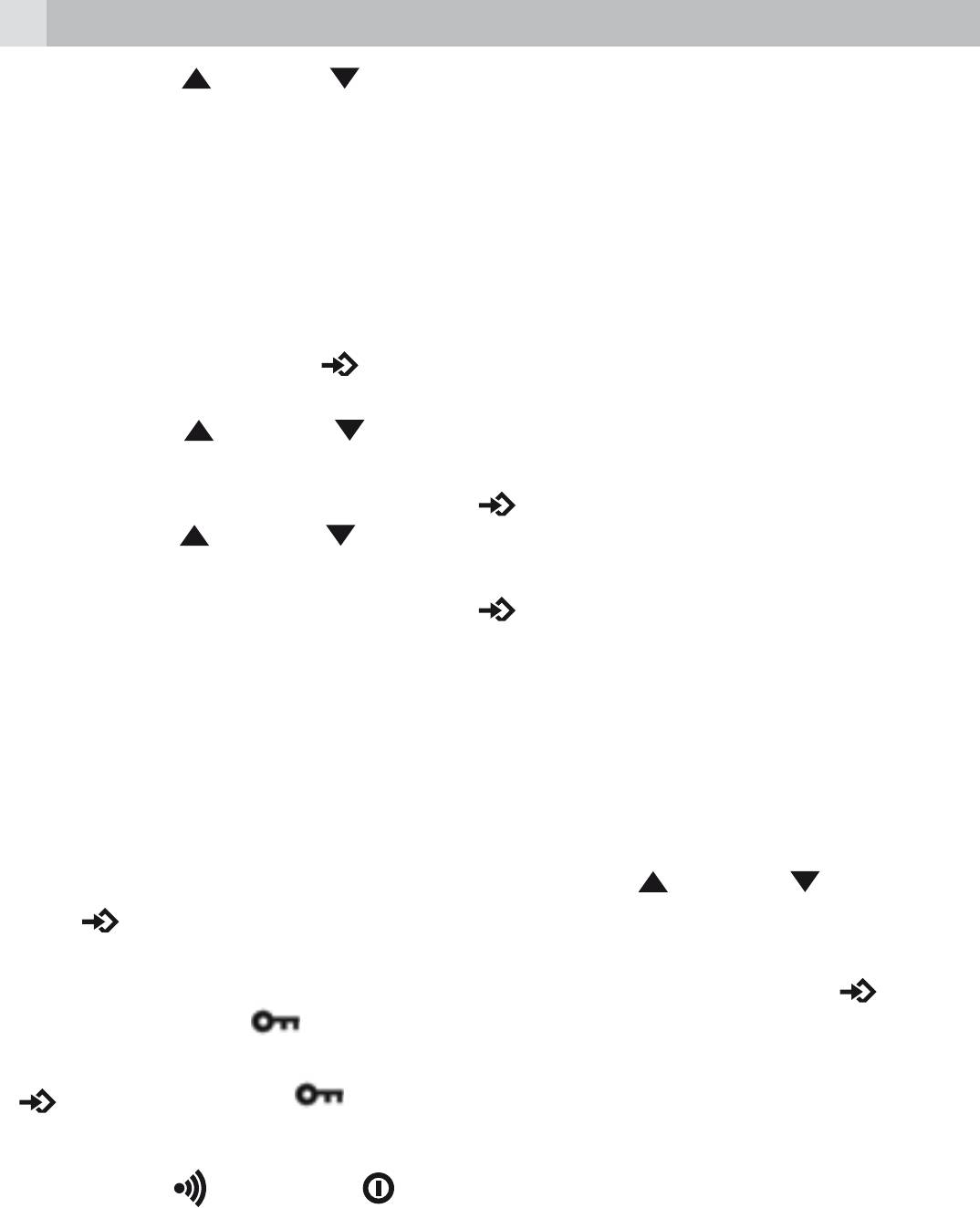
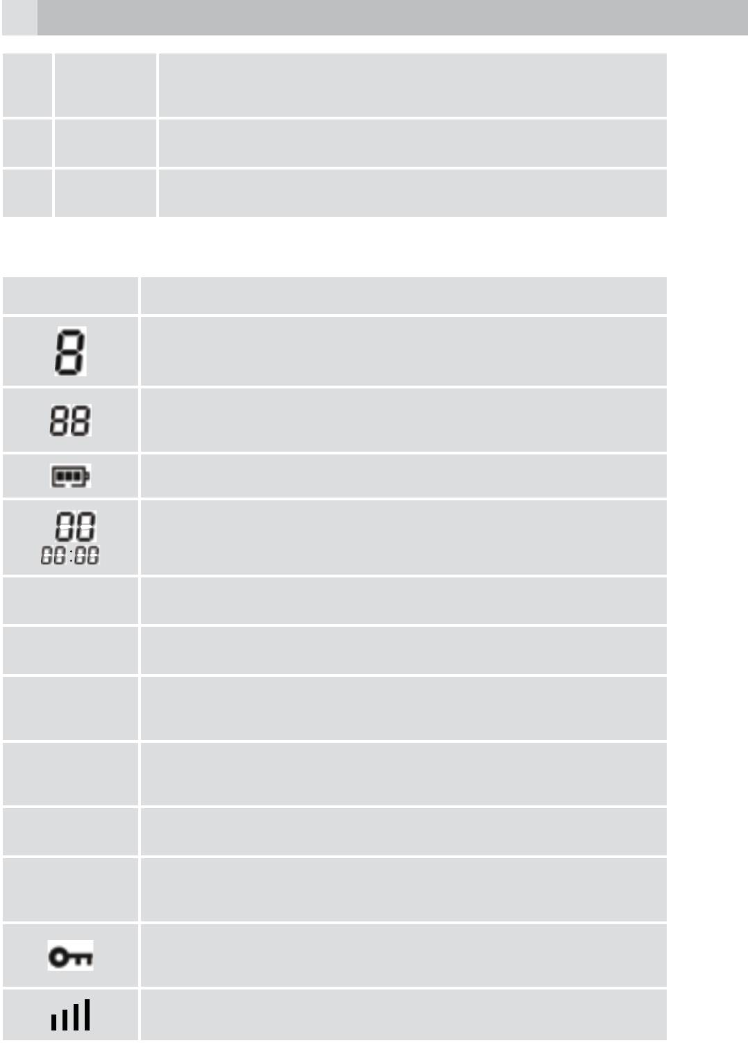
2.2 LCD screen (see P2)
Meaning
Channel number.
Changes from 1 to 8 as selected by the user.
CTCSS code.
Changes from 1 to 38 as selected by the user.
Displays the battery change level.
Displayed when the stop watch function is activated.
Displayed when transmitting a signal.
TX
Displayed when receiving a signal.
RX
Displayed when the dual watch function is turned on.
DCM
Displayed when the Digital Code System is turned
DCS
on.
Displayed when the VOX feature is enabled.
VOX
Displays when the PMR is scanning all channels.
SC
Displayed when the key lock feature is activated.
Displays the current speaker volume level.
3 INSTALLATION
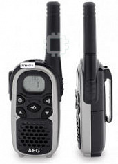
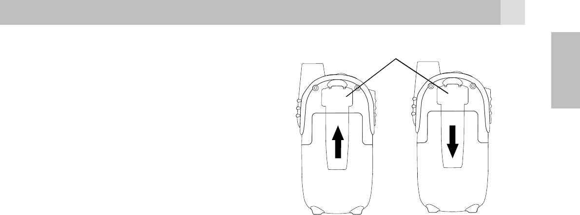
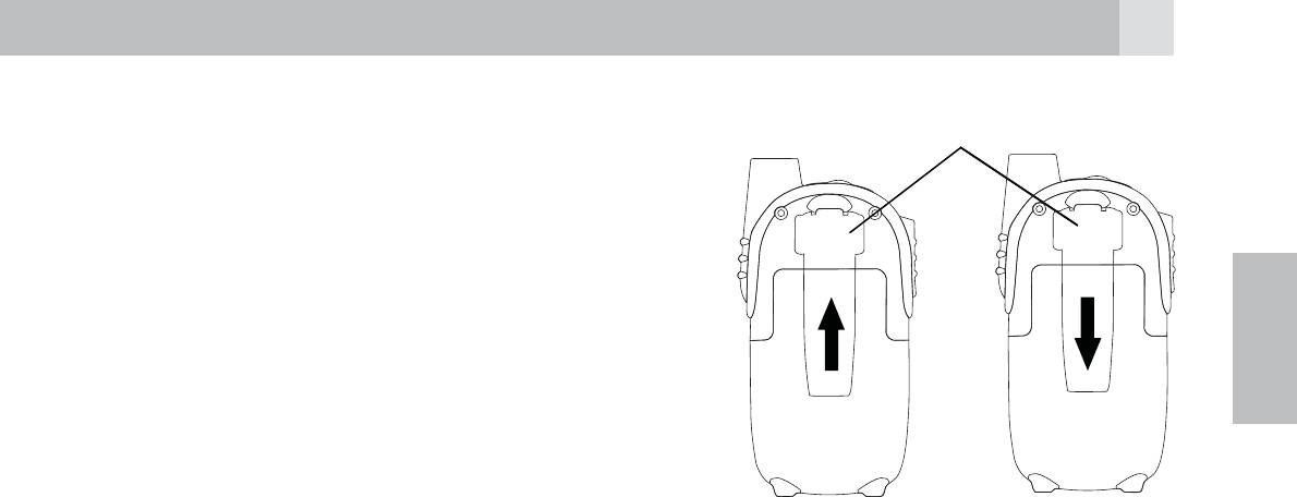
3.1 Removing the belt clip
tPull the belt clip latch forward (away from the PMR).
tWhile pulling the belt clip latch, push up the belt clip as shown in
Fig. 1.
5
3.2 Installing the belt clip
Belt clip latch
tSlide the belt clip into the slot
UK
as shown in Fig. 2.
>A “click” indicates the belt
clip is locked into its position.
Fig. 1 Fig. 2
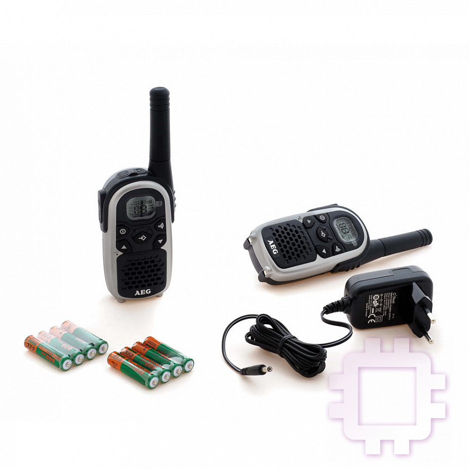
3.3 Installing the batteries (see P3)
Caution:
Observe the proper battery polarity orientation when installing
batteries. Incorrect positioning can damage both the batteries and
the unit.
tSlide down the battery compartment cover.
tInsert the rechargeable batteries by following the orientation as
shown in P3.
tReplace the battery compartment cover.
Important:
Read these safety warnings before you charge the batteries.
tDon’t try to recharge non-rechargeable batteries.
tMake sure the battery compartment cover is securely locked in place
when you are charging the batteries.
tDispose of used batteries safely and in a way that will not harm the
environment, never try to burn them or put them anywhere, they
could get burnt or punctured.
tDon’t leave dead batteries in your PMR units. They might leak if you
do.
3.4 Charging the batteries
3.4.1 With duo charger (model R210/R220) (see P4)
tInsert the small plug on the end of the mains adaptor into the power-
in connection jack at the back of the desktop charger.

6
tPlug the mains adaptor into a 220V AC, 50Hz main socket.
tPlace the PMR units in the charge cradle in an upright position. The
charge LED indicators will light up.
tIt takes about 10 hours to fully recharge the batteries if they are
completely run down. New batteries take up to 14 hours to fully
charge.
Important:
tThe unit must be charged using the mains adaptor provided. Using
any other adaptor will result in non-compliance with EN60950-1 and
will invalidate any approvals and warranty.
tAlways turn off the PMR units when charging. This will shorten the
charging time.
3.4.2 Using the adapter (model R200/R210/R220) (see P5)
tLift the charge socket cover located on the upper side of the PMR.
tInsert the round connector of the 9V DC / 200 mA adaptor into the
charge jack.
tPlug the mains adaptor into a 220 V AC, 50 Hz main socket.
3.5 Battery meter
The battery meter is located in the left corner of the LCD screen. It
appears like a battery with three bars inside. These indicate the amount
of power available. When the battery level reaches it minimum level in
PMR on mode, the unit will emit two beep tones and automatically the
unit will power off.
The unit can detect the battery charge in 4 levels:
Battery charge at high level.
Battery charge at medium level.
Battery charge at low level. At this level, the unit will
emit a “beep” sound for every 10 seconds in normal
mode.
Important: Charge the unit for 10-14 hours.

7
Battery charge at very low level. When the battery
level reach it minimum level in on mode, unit will emit
UK
two beep tone and automatically turn off the power
and proceeds to watch mode.
3.6 Battery life
The unit has a built in power saver to make the batteries last longer.
But when you are not using the units, turn them off to conserve battery
power.
4 OPERATION
4.1 Transmitting range
The talk range depends on the environmental and terrain. It will be
reach up to about 8 km in wide open spaces, without obstructions
such as hills or buildings. Don’t try to use two PMR units which are less
than 1,5 m apart. If you do, you may have experience interference.
Important safety warning:
tTo reduce radio frequency exposure when you are using your PMR,
hold the unit at least 5 cm away from your face.
tNever use your unit outdoors during a thunderstorm.
tDon’t use the unit in the rain.
tIf your unit gets wet, turn it off and remove the batteries. Dry the
battery compartment and leave the cover off for a few hours. Don’t
use the unit until it is completely dry.
tKeep the unit out of reach for babies and young children.
4.2 Turning the unit on/off
To turn on:
tPress and hold the power button
until the LCD screen turns on
and displays the current channel.
To switch off:
tPress and hold the power button
until the LCD screen turns blank.
>You can hear a tone each time to confirm.
8
4.3 Adjusting the speaker volume
The volume level is shown by vertical bars on the LCD screen. You
can change the volume while using your unit, or while the unit is idle
(switched on but not in use).
tPress the up button
to increase or press down button to
decrease the speaker volume.
4.4 Changing channels
The unit has 8 available channels, to communicate with other PMR
users within a range, you must all have your unit tuned to the same
channel.
tPress the menu button
once, the current channel number flashes
on the LCD screen.
tPress the up
or down button to select the desired channel.
>The channel changes from 1 to 8, or vice versa.
tPress the PTT button to confirm the channel setting.
Note:
Refer to the “Channel frequency table“ section of this owner’s manual
for detailed frequency listing.
4.4.1 Setting the CTCSS sub-channel
Each channel also has 38 sub-channels to let you set up group of users
within the same channel for more private communication. If you have
set the sub-channel, you can only communicate with other PMR users
tuned to the same channel and sub-channel.
To turn the sub-channel function off, simply set the sub- channel to
0 (zero). You can communicate with any PMR user set to the same
channel who also turns off the sub-channel operation.
tPress the menu button
twice, the current CTCSS sub-channel
number flashes on the LCD screen.
tPress the up
or down button to select one of the 38 CTCSS
sub-channels.
tPress the PTT button to confirm the sub-channel setting.
9
4.4.2 Setting the DCS advanced digital code
Each channel also has 83 digital codes to let you set up group of users
UK
for more secured private communication.
tPress the menu button
3 times. DCS code is blinking on the LCD
screen.
tPress the up
or down button to select the desired DCS code.
tPress the PTT button to confirm the DCS channel setting.
Transmitting and receiving
tThe PMR transmission is “one way-at-a-time.” While you
are speaking, you can not receive a transmission.
!
tThe PMR is an open-license band. Always identify yourself
when transmitting on the same channel.
4.5 Receiving
The unit is continuously in the receive mode when the unit is turned on
and not transmitting. When a signal is received on the current channel,
R
X
icon will be displayed on the LCD screen
4.6 Transmitting (sending a speech)
tPress and hold the PTT (push to talk) button to transmit your voice.
TX
icon will be displayed on the LCD screen.
tHold the unit in a vertical position with the microphone 5 cm away
from the mouth. While holding the PTT button, speak into the
microphone in a normal tone of voice.
tRelease the PTT button when you have finished speaking.
4.7 Monitor
You can use the monitor feature to check for weak signals on the
current channel.
tPress and hold the menu
and down buttons at the same time.
R
X
icon will be displayed on the LCD screen. Your unit will pick up
signals on the current channel, including background noise.
tPress the menu button
to stop the channel monitoring.

10
4.8 Setting the VOX (voice activated) sensitivity
In VOX mode, the unit will transmit a signal only when it is activated by
your voice or other sounds around you. The unit will transmit further
for 2 seconds even if you stop talking.
The level of VOX sensitivity is shown by a number on the LCD screen.
At the highest level, the units will pickup softer noise (including
background noise); at the lowest level, it will pick up only louder noise.
tPress the menu button
4 times,
VOX
icon will be displayed and
“OF” flashes on the LCD screen.
tPress the up button
to set the VOX sensitivity into maximum level
(the maximum level is 3.)
tTo deactivate the VOX function, press the down button
until “OF”
appears on the LCD screen.
tPress the PTT button to confirm your setting.
VOX
will steady
appear on the LCD screen as along as the VOX feature is activated.
Note:
VOX operation is not recommended if the unit will be used in a noisy
or windy environment.
4.9 Activating the auto channel scan
Channel scan perform searches for active signals in an endless loop for
all 8 channels, 38 CTCSS codes and all 83 DCS codes.
tPress the menu button
5 times,
SC
icon will display on LCD
screen.
tPress the up
or down button to begin scanning channels when
an active signal is detected, channel scan pauses on the active
channel.
tPress the menu button
six times, CTCSS flashes on the LCD
screen press the up
or down button to begin scanning the
CTCSS from 1-38.
tPress the menu button
seven times, DCS flashes on the LCD
screen. Press the up
or down button to begin scanning DCS
code 1-83.
tPress the PTT button to confirm your setting.

11
4.10 Call alert
Your PMR can alert you to incoming signal by emitting an audible call
UK
tone.
4.10.1 Call-ring tone
You can send a call-ring tone to other PMR users to give an alert that
you want to communicate with them.
tPress the call button
.
You will hear a ring tone for about two seconds;
TX
icon appears on
the LCD screen. Any other units within the transmitting range and
tuned to the same channel and sub-channel (if applicable) will hear
the call-ring tone.
4.10.2 Selecting a call- ring tone
The unit is equipped with15 different types of call-ring tones.
tPress the menu button
8 times, the “CA” icon will display and
“01” is blinking on the LCD screen.
tPress the up
or down button to select the desired call-ring
tone.
>A respective call- ring tone sound will be played when changing
from one tone to another.
tPress the PTT button to confirm your setting.
4.11 Setting the Roger beep
The Roger beep is a tone which is automatically transmitted whenever
the PTT button is released. This alerts the receiving party to inform
that you have intentionally ended the transmission and you are now
in receive mode.
tPress the menu button
9 times, the “R0” icon will be displayed
while the “ON” icon is blinking on the LCD screen.
tPress the up
or down button to select the roger beep on/off.
tPress the PTT button to confirm your setting.
4.12 Setting the key tone on or off
This feature allows the unit to emit a confirmation tone on pressing a
button.
tPress the menu button
10 times, the “T0” icon will be displayed
while “ON” icon is blinking on the LCD screen.
12
tPress the up
or down button to select the key tone on/off.
tPress the PTT button to confirm your setting.
4.13 Setting the dual watch mode
Your unit is capable of monitoring two channels, the current and
another (dual watch) channel. If the unit detects a signal on either
channel, it will stop and receive the signal.
tPress the menu button
11 times, “DCM” icon will be displayed
while “OF ” flashes on the LCD screen.
tPress the up
or down button to select the dual watch channel
(1-8, except the current channel).
tContinue pressing the menu button
to change the CTCSS code.
tPress the up
or down button to select the desired CTCSS code
(1-38)
tContinue pressing the menu button
to change the DCS code.
tPress the PTT button to confirm your setting.
5 AUXILIARY FEATURES
5.1 Key lock
The key lock feature allows user to disable the up
or down and
menu
buttons so that the PMR settings could not be changed
accidentally.
tTo activate the key lock feature, press and hold the menu button
until key lock icon
appears on the LCD screen.
tTo deactivate the key Lock feature, press and hold the menu button
until key lock icon disappears on the LCD screen.
Note:
The PTT, call
and power buttons will remain functional even if
the key lock feature is activated.
13
5.2 Stop watch function
tIn standby mode, press and hold the call button
for 3 seconds.
UK
The stop watch icons
will appear on the LCD screen.
tPress the up button
once to start the stop watch. to stop press
again the up button
.
tPress the down button
to reset the timer.
tPress and hold the call button
to exit the stop watch function and
return to standby mode.
5.3 LCD screen back light
Every time a button is pressed (except PTT and call
button), the
LCD screen back light will illuminate for 5 seconds.
5.4 Microphone/earphone/charge jack
The unit is equipped with an auxiliary microphone, earphone and
charge jack located at the top side of the unit. For more information
check www.aegtelphones.eu
6 SPECIFICATIONS
Channels available 8 channels
CTCSS sub-channel 38 for each channel
Output power (TX) 0,5 W (Max)
Range up to 8 km
Channel frequency table
Channel Frequency (MHz) Channel Frequency (MHz)
1 446.00625 5 446.05625
2 446.01875 6 446.06875
3 446.03125 7 446.08125
4 446.03125 8 446.09375

14
7 Safety
Damaged antenna
Do not use any PMR that has a damaged antenna. If a
!
damaged antenna comes in contact with the skin, a minor
burn may result.
Rechargeable batteries
All batteries can cause property damage and/or bodily
injury such as burns if conductive material such as jewelry,
keys, or beaded chains touches exposed terminals. The
!
material may complete an electrical circuit (short circuit) and
become quite hot. Exercise care in handling any charged
battery, particularly when placing it inside a pocket, purse,
or other container with metal objects.
Warning for vehicles with an air bag
Do not place your unit in the area over an air bag or in the
air bag deployment area. Air bags inflate with great force.
!
If a unit is placed in the air bag deployment area and the air
bag inflates, the device may be propelled with great force
and cause serious injury to the occupants of the vehicle.
Potentially explosive atmospheres
Turn your unit off when in any area with a potentially
explosive atmosphere, unless it is a type especially qualified
!
for such use (for example, factory mutual approved). Sparks
in such areas could cause an explosion or fire resulting in
injury or even death.
Batteries
Do not replace or charge batteries in a potentially explosive
!
atmosphere. Contact sparking may occur while installing or
removing batteries and cause an explosion.
Blasting caps and areas
To avoid possible interference with blasting operations,
turn your device off near electrical blasting caps or in a
!
“blasting area” or in areas posted: “Turn off the two way
radio.” Obey all signs and instructions.
15
NOTE:
Areas with potentially explosive atmospheres are often, but not always
UK
clearly marked. They include fueling areas such as below deck on
boats; fuel or chemical transfer or storage facilities; areas where the air
contains chemicals or particles, such as grain, dust, or metal powders;
and any other area where you would normally be advised to turn off
your vehicle engine.
8 CE DECLARATION
This product is in compliance with the essential requirements and
other relevant provisions of the R&TTE directive 1999/5/EC.
The Declaration of conformity can be found on:
www.aegtelephones.eu
9 DISPOSAL OF THE DEVICE
(ENVIRONMENT)
At the end of the product lifecycle, you should not throw this
product into the normal household garbage but bring the product
to a collection point for the recycling of electrical and electronic
equipments. The symbol on the product, user guide and/or box
indicate this. Some of the product materials can be re-used if you bring
them to a recycling point. By reusing some parts or raw materials from
used products you make an important contribution to the protection
of the environment. Please contact your local authorities in case you
need more information on the collection points in your area.
Batteries must be removed before disposing of the device.
Dispose of the batteries in an environmental manner according to
your country regulations.

16
10 CLEANING AND CARE
Do not clean any part of your unit with benzene, thinners or other
solvent chemicals as this may cause permanent damage which is not
covered by the guarantee.
When necessary, clean it with a damp cloth.
Keep your unit away from hot, humid conditions or strong sunlight,
and don‘t let it get wet.
11 GUARANTEE AND SERVICE
The unit is guaranteed for 24 months from the date of purchase
shown on your sales receipt. This guarantee does not cover any
faults or defects caused by accidents, misuse, fair wear and tear,
neglect,tampering with the equipment, or any attempt at adjustment
or repair other than through approved agents.
Please keep your sales (till) receipt this is your proof of guarantee.
11.1 While the unit is under Guarantee
tPack up all parts of your unit, using the original package.
tReturn the unit to the shop where you bought it, making sure you
take your sales receipt.
tRemember to include the mains adapter. (if applicable)
11.2 After the Guarantee has expired
If the unit is no longer under Guarantee, contact us via
www.aegtelephones.eu
17
1 UNSER EINSATZ FÜR DIE UMWELT
Vielen Dank, dass Sie sich für dieses Produkt entschieden haben.
Dieses Gerät wurde mit größter Sorgfalt entwickelt und gefertigt, um
Ihnen ein exzellentes Produkt zu bieten und gleichzeitig die Umwelt
zu schonen. Deshalb liegt diesem Produkt eine Kurzanleitung bei, um
die Papiermenge zu reduzieren. So müssen weniger Bäume für die
DE
Herstellung von Papier abgeholzt werden. Vielen Dank, dass Sie uns
beim Umweltschutz unterstützen.
2 EINFÜHRUNG
2.1 Übersicht über Ihr Funkgerät (siehe P1)
# Bedeutung
LCD-Anzeige
1
tZeigt den derzeitig ausgewählten Kanal und
andere Funksymbole an.
Ruftaste
2
tDrücken, um einen Rufton an andere PMR-Geräte
zu senden.
Aufwärts-/Abwärtstaste
tDrücken, um Kanäle zu wechseln oder um
3
/
die Lautstärke oder Einstellungen beim
Programmieren auszuwählen.
Menütaste
4
tDrücken, um zwischen den einzelnen Modi hin
und her zu schalten.
Lautsprecher
5
Mikrofon
6 MIC
Ein-/Austaste
7
tGedrückt halten, um das Gerät ein- oder
auszuschalten.
18
PTT (push to talk)-Taste
8 PTT
tGedrückt halten, um senden zu können.
Mikrofon, Kopfhörer, Ladebuchse
9
Antenne
10
2.2 LCD-Anzeige (siehe P2)
Bedeutung
Kanalnummer.
Je nach Auswahl von1bis8.
CTCSS-Code.
Je nach Auswahl von1bis38.
Zeigt den Akku-Ladezustand an.
Wird angezeigt, wenn die Stoppuhrfunktion aktiviert
ist.
Wird angezeigt, wenn ein Signal gesendet wird.
TX
Wird angezeigt, wenn ein Signal empfangen wird.
RX
Wird angezeigt, wenn die Zweikanalüber-
DCM
wachungsfunktion eingeschaltet ist.
Wird angezeigt, wenn das digitale Codesystem
DCS
(DCS) eingeschaltet ist.
V
Wird angezeigt, wenn die VOX-Funktion aktiviert ist.
OX
Wird angezeigt, wenn das PMR-Gerät alle Kanäle
SC
absucht (Scan-Funktion).
Wird angezeigt, wenn die Tastensperrfunktion
aktiviert ist.
Zeigt die derzeitige Lautstärke an.
19
Gürtelclipverriegelung
3 INSTALLATION
3.1 Den Gürtelclip entfernen
tZiehen Sie an der Gürtelclip-
verriegelung des PMR-Geräts.
tWährend des Ziehens an der
DE
Gürtelclipverriegelung drücken Sie
gleichzeitig den Gürtelclip nach
oben, siehe Abb.1.
Fig. 1 Fig. 2
3.2 Den Gürtelclip anbringen
tSchieben Sie den Gürtelclip in den dafür vorgesehenen Einschub,
sieheAbb.2.
>Durch ein Klicken wird angezeigt, dass der Gürtelclip in seiner
Position eingerastet ist.
3.3 Die Akkus einlegen (siehe P3)
Achtung:
Achten Sie beim Einlegen der Akkus auf die richtige Ausrichtung der
Polarität. Durch falsches Einlegen können sowohl Akkus als auch das
Gerät beschädigt werden.
tSchieben Sie die Akku-Fachabdeckung nach unten.
tLegen Sie die aufladbaren Akkus der in P3 gezeigten Ausrichtung
entsprechend ein.
tSchließen Sie die Akku-Fachabdeckung wieder.
Wichtig:
Lesen Sie vor dem Aufladen der Akkus diese Sicherheits-
warnungen durch.
tFür die Ladefunktion dürfen auf keinen Fall herkömmliche
Einwegbatterien verwendet werden, da dies zu erheblichen
Beschädigungen führen kann, wodurch die Garantie des Gerätes
erlischt.
tStellen Sie sicher, dass beim Laden der Akkus die Abdeckung des
Akku-Fach sicher eingerastet ist.
tEntsorgen Sie defekte Akkus ordnungsgemäß und so, dass sie die
Umwelt nicht belasten, versuchen Sie nie, sie zu verbrennen und

20
lassen Sie sie nicht an Orten, wo sie verbrannt oder aufgestochen
werden könnten.
tLassen Sie die leeren Akkus nicht in Ihren PMR-Geräten. Sie könnten
dort auslaufen.
3.4 Die Akkus aufladen
3.4.1 Mit dem Duo-Ladegerät (Modell R210/R220) (siehe P4)
tStecken Sie den schmalen Stecker des Netzteils in die
Stromanschlussbuchse hinten am Desktop-Ladegerät.
tStecken Sie das Netzteil in eine Netzsteckdose (220VWS, 50 Hz).
tStellen Sie die PMR-Geräte senkrecht in die Auflade-Basisstationen.
Die LED-Anzeige für das Aufladen leuchtet auf.
tWenn die Akkus vollständig leer sind, braucht es ca. 10 Stunden, um
sie wieder voll aufzuladen. Neue Akkus brauchen bis zu14Stunden,
um sie völlig aufzuladen.
Wichtig:
tDas PMR-Gerät muss mit dem mitgelieferten Netzteil aufgeladen
werden. Die Verwendung eines anderen Netzteils bedeutet
ein Verstoß gegen die Norm EN60950-1 und führt dazu, dass
Zulassungen und Garantien ungültig werden.
tSchalten Sie beim Aufladen die PMR-Geräte immer aus. Dadurch
wird die Ladezeit verkürzt.
3.4.2 Benutzen Sie den Adapter (Modell R200/R210/R220)
(siehe P5)
tNehmen Sie die Abdeckung der Ladebuchse oben an Ihrem PMR-
Gerät ab.
tStecken Sie den Rundanschluss des Adapters (9 V GS,200 mA) in
die Ladebuchse.
tStecken Sie das Netzteil in eine Netzsteckdose (220 V WS, 50 Hz).
3.5 Akku-Anzeige
Die Akku-Anzeige befindet sich in der linken Ecke auf der LCD-
Anzeige. Er sieht aus wie eine Batterie mit drei Balken im Inneren.
Diese zeigen die noch zur Verfügung stehende Energie an. Wenn die
Akkus ihren niedrigsten Ladezustand erreicht haben und das PMR-


