AEG MBS 30 Turbo: инструкция
Раздел: Электроинструменты
Тип: Пила циркулярная
Характеристики, спецификации
Инструкция к Пиле циркулярной AEG MBS 30 Turbo
MBS 30 Turbo
19
Technical Data,safety instructions, Specied Conditions of Use, EC-Declaration of Conformity,
Please read and save
English
Characteristics, Maintenance, Symbols
these instructions!
Technische Daten, Sicherheitshinweise, Bestimmungsgemäße Verwendung, CE-
Bitte lesen und
Deutsch
Konformitätserklärung, Merkmale, Wartung, Symbole
aufbewahren!
Caractéristiques techniques, Instructions de sécurité, Utilisation conforme aux prescriptions,
Prière de lire et de
Français
Declaration CE de Conformité, Description, Entretien, Symboles
conserver!
Dati tecnici, Norme di sicurezza, Utilizzo conforme, Dicharazione di Conformità CE,
Si prega di leggere le
Italiano
Breve Indicazione, Manutenzione, Simboli
istruzioni e di conservarle!
Datos técnicos, Instrucciones de seguridad, Aplicación de acuerdo a la nalidad,
Lea y conserve estas
Español
Declaracion de Conformidad CE, Señalización, Mantenimiento, Símbolos
instrucciones por favor!
Características técnicas, Instruções de segurança, Utilização autorizada,
Por favor leia e conserve em
Português
Declaração de Conformidade CE, Características, Manutenção, Symbole
seu poder!
Technische gegevens, Veiligheidsadviezen, Voorgeschreven gebruik van het systeem,
Lees en let goed op
Nederlands
EC-Konformiteitsverklaring, Kenmerken, Onderhoud, Symbolen
deze adviezen!
Tekniske data, Sikkerhedshenvisninger, Tiltænkt formål, CE-Konformitetserklæring,
Vær venlig at læse og
Dansk
Beskrivelse, Vedligeholdelse, Symboler
opbevare!
Tekniske data, Spesielle sikkerhetshenvisninger, Formålsmessig bruk,
Norsk
CE-Samsvarserklæring, Kjennetegn, Vedlikehold, Symboler
Tekniska data, Säkerhetsutrustning, Använd maskinen Enligt anvisningarna,
Svenska
CE-Försäkran, Kännemärke, Skötsel, Symboler
Tekniset arvot, Turvallisuusohjeet, Tarkoituksenmukainen käyttö,
Suomi
Todistus CE-standardinmukaisuudesta, Akku, Ominaisuudet, Huolto, Symbolit
Teknik veriler, Güvenliğiniz için talimatlar, Kullanim, CE uygunluk beyanice,
Özellikler, Bakim, Semboller
TÜRKÇE
Technická data, Speciální bezpečnostní upozornění, Oblast využití, Ce-prohlášení o shodě,
Česky
Upozornění, Údržba, Symboly
Technické údaje, Špeciálne bezpečnostné pokyny, Použitie podľa predpisov,
Slovensky
CE-Vyhlásenie konformity, Znaky, Údrzba, Symboly
Dane techniczne, Specjalne zalecenia dotyczące bezpieczeństwa, Użytkowanie zgodne z
przeznaczeniem, Świadectwo zgodności ce, Właściwości, Gwarancja, Symbole
Polski
Műszaki adatok, Különleges biztonsági tudnivalók, Rendeltetésszerű használat,
Magyar
Ce-azonossági nyilatkozat, Jellegzetességek, Karbantartás, Szimbólumok
Tehnični podatki, Specialni varnostni napotki, Uporaba v skladu z namembnostjo,
Slovensko
Ce-izjava o konformnosti, Značilnosti, Vzdrževanje, Simboli
Tehnički podaci, Specijalne sigurnosne upute, Propisna upotreba,
Hvratski
CE-Izjava konformnosti, Obilježja, Održavanje, Simboli
Tehniskie dati, Speciālie drošības noteikumi, Noteikumiem atbilstošs izmantojums, Atbilstība
Latviski
CE normām, Pazīmes, Apkope, Simboli
Techniniai duomenys, Ypatingos saugumo nuorodos, Naudojimas pagal paskirtį,
LIETUVIŠKAI
CE Atitikties pareiškimas, Požymiai, Techninis aptarnavimas, Simboliai
Tehnilised andmed, Spetsiaalsed turvajuhised, Kasutamine vastavalt otstarbele,
EÜ Vastavusavaldus, Tunnused, Hooldus, Sümbolid
Eesti
Òåõíè÷åñêèå äàííûå, Ðåêîìåíäàöèè ïî òåõíèêå áåçîïàñíîñòè,
Èñïîëüçî- âàíèå, Õàðàêòåðèñòèêè, Îáñëóæèâàíèå, Ñèìâîëû
Техническиданни, Специалниуказаниязабезопасност, Използванепопредназначение,
БЪЛГАРСКИ
СЕ-Декларациязасъответствие, Характеристики, Поддръжка, Символи
115 119
Date tehnice, Instrucţiuni de securitate, Condiţii de utilizare specicate, Declaraţie de
МАКЕДОНСКИ
conformitate, Alimentare de la reţea, Caracteristici, Intreţinere, Simboluri
Технички Податоци, Упатство За Употреба, Специфицирани Услови На Употреба,
ROMÂNIA
Еу-декларација За Сообразност, Батерии, Карактеристики, Одржување, Симболи
1231111071039995918783797571676355 595147433935312723
技术数据, 特殊安全指示, 正确地使用机器, 欧洲安全规定说明,
中文
蓄电池, 特点, 维修, 符号
Aufnahme
aufschrauben
Aufnahme
aufschrauben
IIII
V
VIII
II
x cm
x cm
Accessory
Zubehör
Accessoires
Accessorio
Accessorio Acessório
Toebehoren
Tilbehør
Tilbehør
Tillbehör
Lisälaite
Εξαρτήματα
Aksesuar
říší
Príslušenstv
Wyposażenie
Azokat a tartozékokat
IX
Oprema
Piederumi
Priedas
Tarvikud
îïîëíèòåëü
Аксесоари
Accesoriu
ополнителна
опрема
配件
x cm
x cm
VIIV
VII
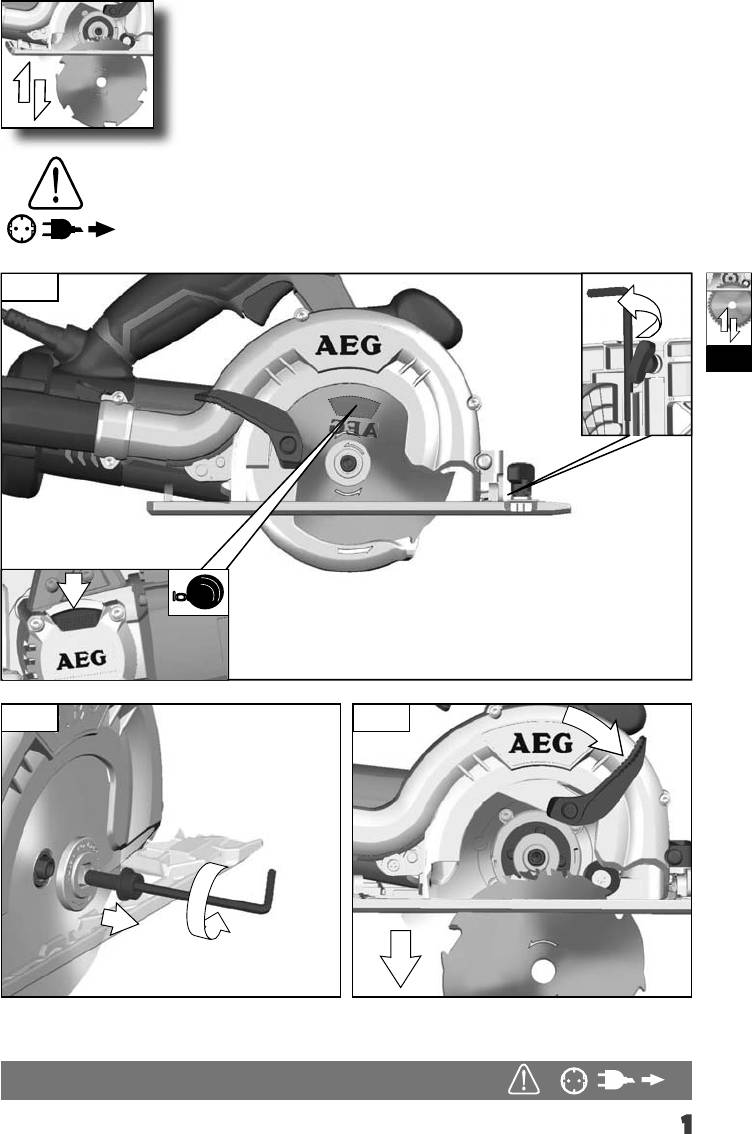
1.
I
1
lock
2. 3.
3
2
4
1
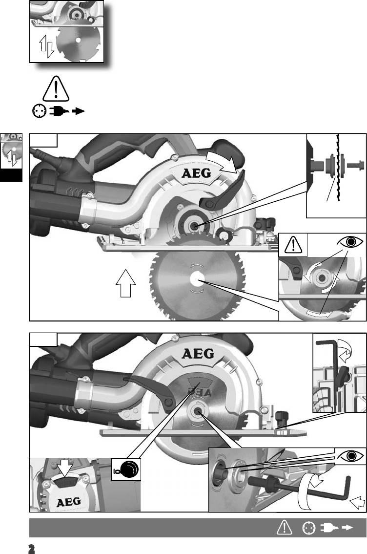
1.
4.
1
I
ø 20,0 mm
ø 22,2 mm
2
5.
3
lock
4
2
2 x
I
ø 20,0 mm
ø 20,0 mm
ø 22,2 mm
3
1
II
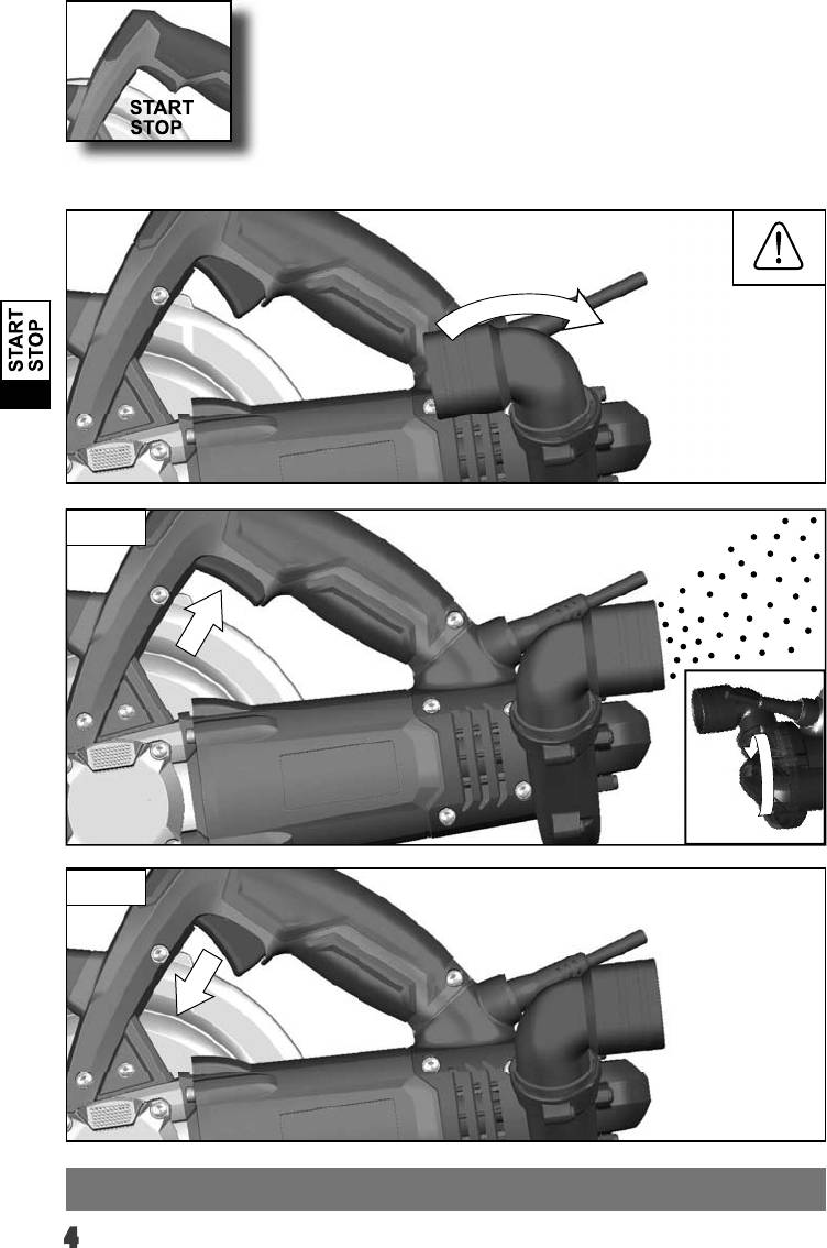
1.
Start
2
Stop
3
4
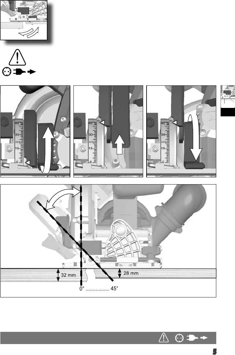
1.
III
28 mm
32 mm
0° .................
45°
5
45°
28 mm
32 mm
0° .................
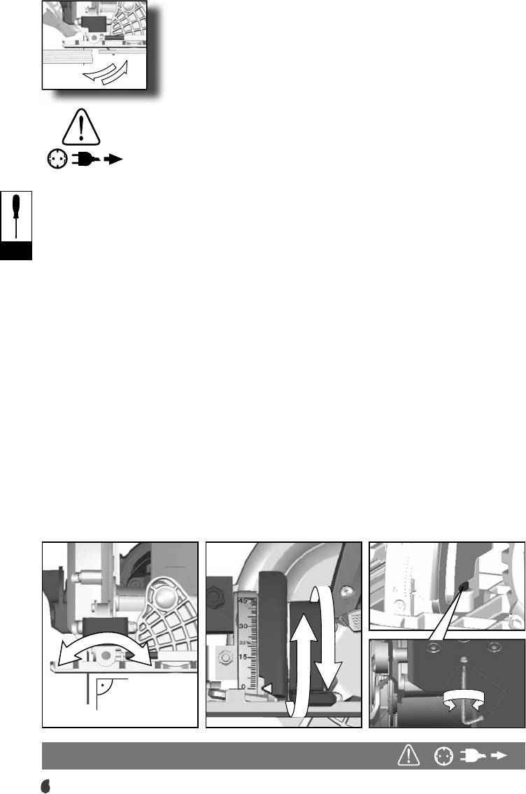
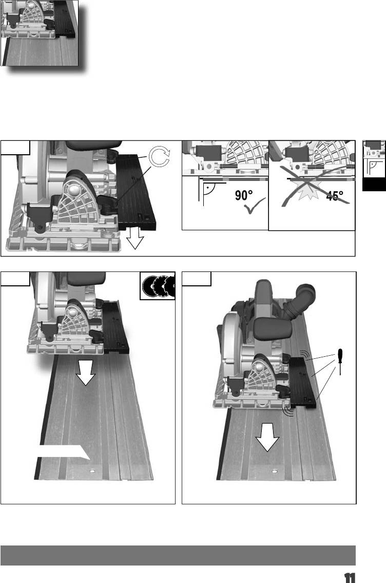
If a correction of the 90° angle of the guide-plate to the saw
Ak je potrebná korektúra 90° uhlu vodiacej platne k pílovému
blade is necessary, use the correction screw.
listu, použite korekčnú skrutku.
Falls eine Korrektur des 90° Winkels der Führungsplatte zum
Jeżeli konieczne jest skorygowanie kąta ustawienia płytki
Sägeblatt nötig ist, diese mit der Korrekturschraube durchführen
prowadzącej 90° w stosunku do brzeszczota, należy
wykorzystać do tego celu śrubę regulacyjną.
Si une correction de l’angle à 90° de la plaque de base par
rapport à la lame de scie s’avère nécessaire, il convient alors
Ha az alaplap és a fűrészlap által bezárt 90 fokos szög
d’avoir recours à la
korrekcióra szorul, használja az állító csavart.
III
vis de correction.
Če je potrebna korektura 90° kota vodilne plošče k žaginemu
Nella caso in cui si rendesse necessaria una correzione dell
listu, to opravite s pomočjo korekturnega vijaka.
‘angolo di 90° della piastra di base rispetto alla lama, questa
Ako je potrebno korektura kuta vodeće ploče od 90° prema listu
potrà essere effettuata agendo sulla vite di correzione.
pile, ovu izvesti sa vijkom za korekturu.
Si es necesario un ajuste o corrección de perpendicularidad
Gadījumā, ja nepieciešama atbalsta plāksnes 90° leņķa
(90°) del disco de sierra actuar sobre el tornillo de ajuste.
korekcija attiecībā pret zāģa ripu, izmantojiet korekcijas skrūvi.
Caso se torne necessário corrigir a esquadria da base em
Jei tarp kreipiamosios ir pjūklo reikalinga 90° laipsnių pataisa,
relação ao disco de corte, agir sobre o parafuso de afi nação.
tai atlikite pataisos varžtu.
Indien een korrektie van de 90° hoek van de bodemplaat
Juhul kui on vaja parandada juhtplaadi 90° nurka saelehe
ten opzichte van het zaagblad nodig is kan deze worden
suhtes, siis tehke seda korrigeeriva kruviga.
gekorrigeerd met de korrektieschroef.
Для регулировки угла 90 град направляющей шины
Såfremt det er nødvendigt med en korrektion af bundpladens
пильного полотна служит
90° vinkel i forhold til savklingen, gennemføres denne med
регулировочный винт Ако е необходима корекция на ъгъла
korrektionsskruen.
от 90° на
Hvis det er nødvendig å foreta en justering av 90°-vinkelen på
водещата плоча спрямо режещия диск, направете я с
føringsplaten i forhold til
коригиращия винт.
sagbladet, må dette gjøres med justeringsskruen.
Dacă este necesară o corecţie în unghi de 90° a plăcii de
Med ställskruv är det möjligt att justera 90°- vinkeln, bottenplatta
ghidare faţă de lama ferăstraului, utilizaţi şurubul de corecţie.
till sågklingan.
Доколку е потребно корегирање на аголот од 90° водечката
Mikäli pohjalevyn 90°-kulman oikaisu sahanterään nähden on
површина кон сечилото на пилата, користет го шрафот за
tarpeen, oikaisu suoritetaan oikaisuruuvista.
корекција.
Kılavuz levhanın testere bıçağına 90°’lik konumunda bir
如果必须更改导引板和锯刀片之间的角度(90 度),则要调整
düzeltme gerekiyorsa, bunu düzeltme vidası ile yapın.
校正螺丝。
Je-li nutná oprava kolmosti vodicí desky k pilovému kotouči,
proveďte to nastavovacím šroubem.
1
3
2
90°
6
x cm
x cm
1.
IV
1
2
2.
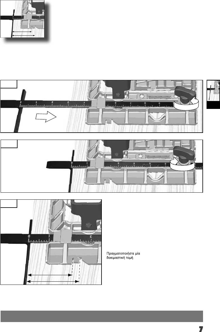
Carry out a test cut
Vykonať skušobný rez.
3.
Probeschnitt durchführen
Wykonac próbę cięcia
Effectuer une coupe d‘essai
Végezzen teszvágást
Effettuare un taglio di prova
Opravite preizkusni rez!
Efectuar corte de prueba
Izvesti probno rezanje
Efectuar experiências de corte
Jāveic izmēģinājuma
griezums!
Proefsnede maken
Atlikite bandomąjį pjūvį!
Foretages et prøvesnit
Teha proovilõige!
Foreta prøvekutt
Выполните пробный проход
Gör ett provsnitt!
Направете пробно рязане!
45°
Efectuaţi un test de tăiere
0°
Deneme kesmesi yapın
Да се направи пробно
сечење
Proveďte zkušební řez.
x cm
x cm
7
1.
1
V
2.
3
0
5
10
15
20
2
25
30
0 – 32 mm
8
V
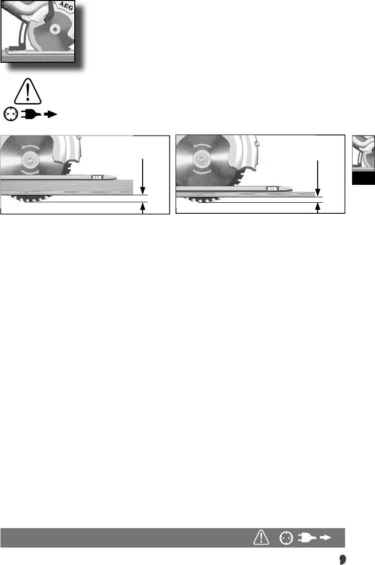
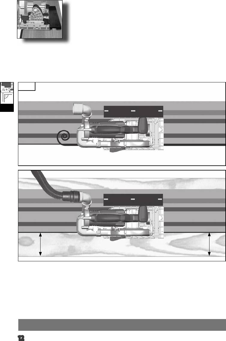
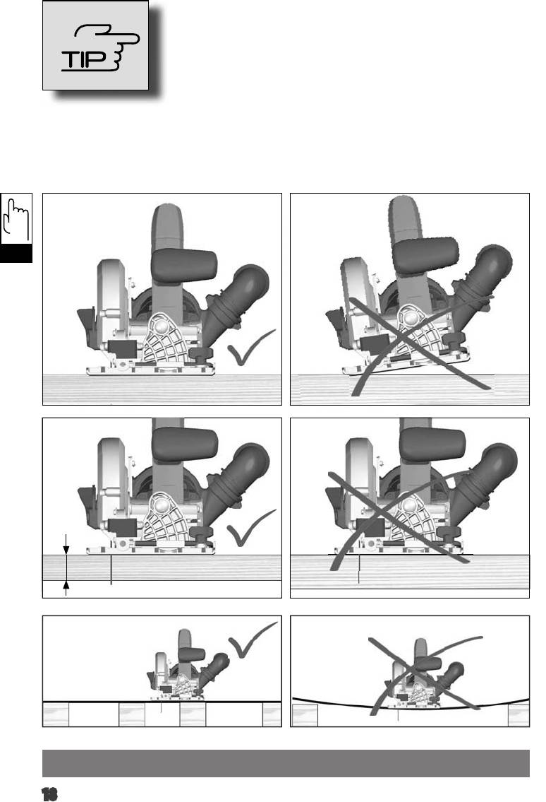
Adjust the cutting depth to the thickness of the workpiece. Less
Hrúbku rezu prispôsobte hrúbke obrobka. Pod obrobkom by malo
than a full tooth of the blade teeth should be visible below the
byť vidieť menej pílového listu ako plnú výšku zuba píly.
workpiece.
Głębokość cięcia należy dopasować do grubości obrabianego
Passen Sie die Schnitttiefe an die Dicke des Werkstücks an.
przedmiotu. Powinno być widoczne mniej jak pełna wysokość
Es sollte weniger als eine volle Zahnhöhe unter dem Werkstück
zębów pod obrabianym przedmioten.
sichtbar sein.
A vágási mélységet a munkadarab vastagságának megfelelően
Adapter la profondeur de coupe à l’épaisseur de la pièce. Moins
kell megválasztani. A fűrészlapból a munkadarab alatt kevesebb
d’une dent complète devrait apparaître sous la pièce.
mind egy teljes fogmagasságnyinak kell kilátszania.
Adattare la profondità di taglio allo spessore del pezzo in
Prosimo, da globino reza prilagodite debelini obdelovanca. Znaša
lavorazione. Nella parte inferiore del pezzo in lavorazione
naj manj kot višina zoba, ki je vidna pod obdelovancem.
dovrebbe essere visibile meno della completa altezza del dente.
Prilagodite dubinu rezanja debljini izratka. Ispod izratka treba biti
Adaptar la profundidad de corte al grosor de la pieza de trabajo.
vidljiv manje od jedan puni zub.
La hoja de sierra no deberá sobresalir más de un diente de la
Izvçlieties zâìçðanas dziïumu, kas atbilst zâìçjamâ priekðmeta
pieza de trabajo.
biezumam. Zâìçðanas dziïumam jâbût tik lielam, lai zem zâìçjamâ
Adaptar a profundidade de corte à espessura da peça a ser
priekðmeta redzamâs asmens daïas augstums bûtu mazâks par
trabalhada. Deveria estar visível por aproximadamente menos do
asmens zobu augstumu.
que uma altura de dente abaixo da peça a ser trabalhada.
Pjovimo gylá tinkamai nustatykite pagal ruoðinio storá. Ruoðinio
Pas de zaagdiepte aan de dikte van het werkstuk aan. Er
apaèioje turi matytis ðiek tiek maþiau, nei per visà pjûklo danties
dient minder dan een volledige tandhoogte onder het werkstuk
aukðtá, iðlindusi disko dalis.
zichtbaar te zijn.
Kohandage lõikesügavus tooriku paksusega. Saeketas võib
Tilpas skæredybden efter arbejdsemnets tykkelse. Der må
tooriku alt vähem kui ühe täishamba võrra välja ulatuda.
maksimalt være en hel tandhøjde synlig under emnet.
Устанавливайте глубину реза в соответствии с толщиной
Tilpass skjæredybden til tykkelsen på arbeidsstykket. Det skal
детали. Под деталью пильное полотно не должно
være mindre enn en full tannhøyde synlig under arbeidsstykket.
высовываться более чем на один зуб.
Anpassa sågdjupet till arbetsstyckets tjocklek. Den synliga delen
Винаги настройвайте дълбочината на рязане съобразно
av en tand under arbetsstycket måste vara mindre än en hel tand.
дебелината на стената на обработвания детайл. От
обратната страна на детайла дискът трябва да се подава на
Aseta leikkaussyvyys työkappaleen paksuuden mukaan.
разстояние, по-малко от една височина на зъба.
Työkappaleen alla tulisi terää näkyä korkeintaan täysi
hammaskorkeus.
Adaptaţi adâncimea de tăiere la grosimea piesei de lucru.
Sub piesa de lucru ar trebui să se vadă mai puţin de înălţimea
Προσαρμόστε το βάθος κοπής στο πάχος του υπό κατεργασία
întreagă a unui dinte.
τεμαχίου. Κάτω το υπό κατεργασία τεμάχιο πρέπει να φαίνεται
λιγότερο από ένα ολόκληρο δόντι του πριονόδισκου.
Прилагодете ја длабочината на засекот во зависност од
густината на обработуваното парче. Нешто помалку од цел
Kesme derinliğini iş parçasının kalınlığına göre ayarlayın. İş
забец од сечилото треба да биде видлив под работното
parçası altında tam diş uzunluğunun daha azı görünmelidir.
парче.
Přizpůsobte hloubku řezu tloušťce obrobku. Pod obrobkem by
根 据 工 件 的 厚 度 设 定 锯 深 。 不 可 以 让 锯 齿
měla být viditelná méně než celá výška zubu.
完 全 突 出 於 工 件 之 外 。
9
1. 2.
VI
3.
10
1.
VII
90°
45°
3.2.
Ident-Nr. 4932 3525 58
11
45°
45°
90°
90°
4.
VII
x cm
x cm
12
Aufnahme
aufschrauben
V
2
1
3
click
3
1
2
13
Aufnahme
aufschrauben
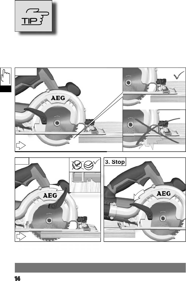
1. Start
TIP
2.
3. Stop
14
3. Stop
VI
0° 45°
Aufnahme
aufschrauben
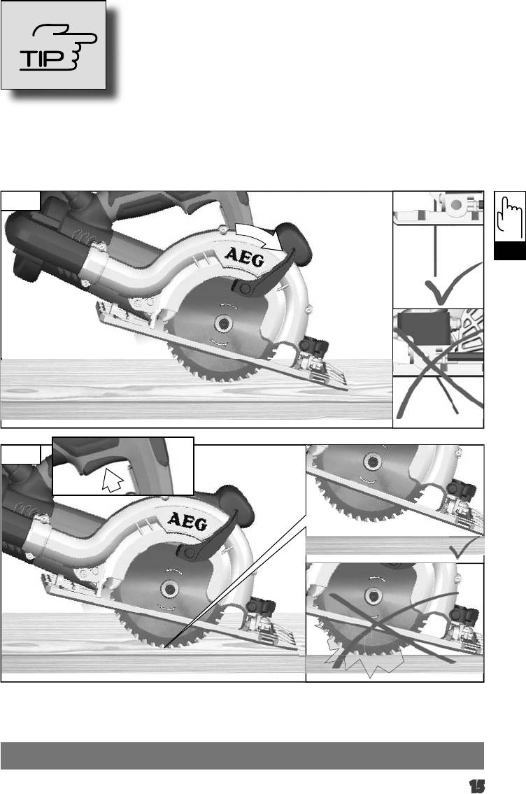
1.
TIP
1
VI
0°
> 0°
2.
15
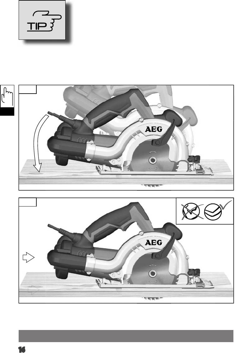
Aufnahme
aufschrauben
3.
TIP
VI
4.
16
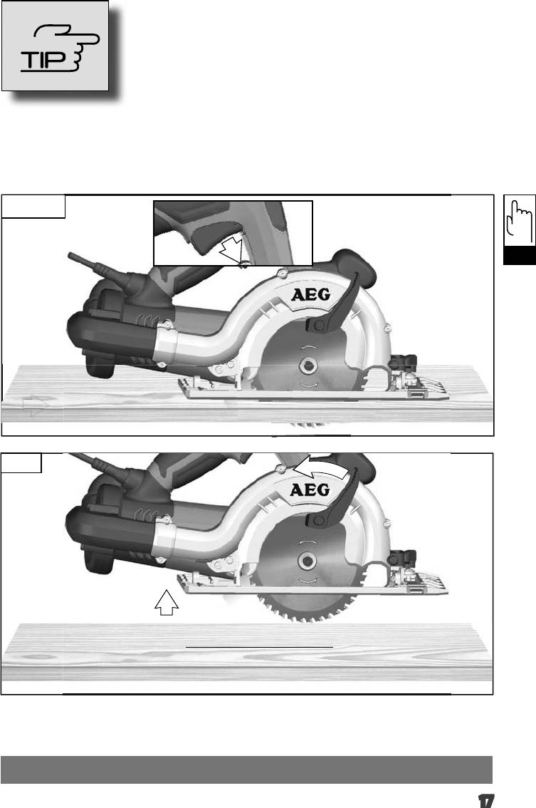
Aufnahme
aufschrauben
5. Stop
TIP
VI
6.
17
Aufnahme
aufschrauben
TIP
VI
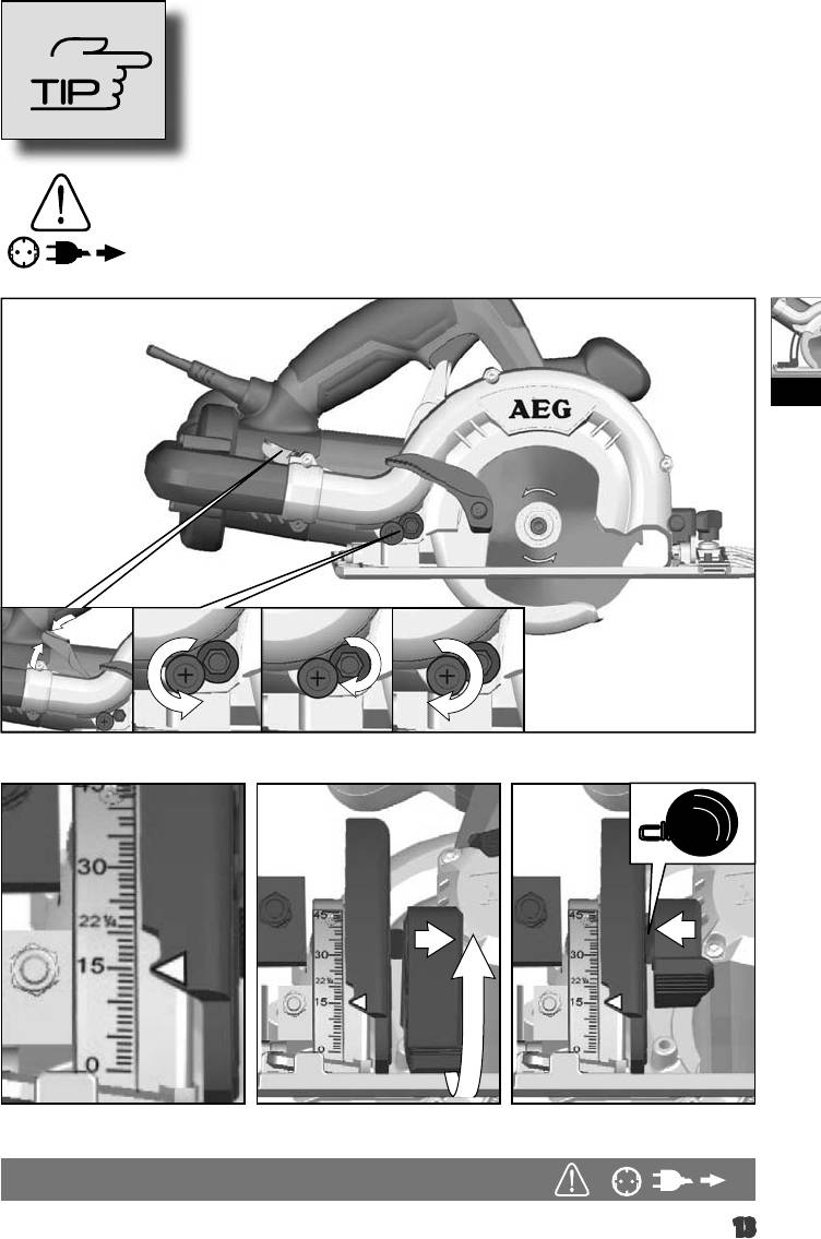
max. 32 mm
18
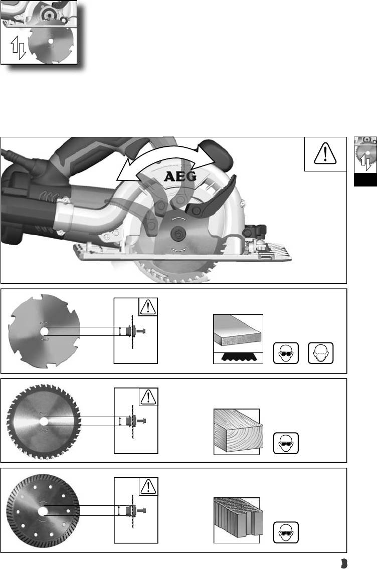
TECHNICAL DATA Fiber Cement Saw
MBS 30 Turbo
Rated Input ...........................................
................1010 W
Noise/vibration information
-1
No-load speed ............................................
................9250 min
Measured values determined according to EN 60745.
Saw blade dia. x hole dia ...............................
...........127 x 20 mm
Typically, the A-weighted noise levels of the tool are:
Diamond wheel dia. x hole dia ......................
........125 x 22,2 mm
..........94 dB(A)
Sound pressure level (K = 3 dB(A)) ................................
Cutting depth at 90° ......................................
....................32 mm
........105 dB(A)
Sound power level (K = 3 dB(A))....................................
Cutting depth at 45° ......................................
....................28 mm
Wear ear protectors!
Weight without cable ....................................
...................3,3 kg
Total vibration values (vector sum in the three axes)
determined according to EN 60745.
Vibration emission value a
h
2
........ 3,7 m/s
sawing into wood ..........................................................
2
........ 1,5 m/s
Uncertainty K= ..............................................................
2
........ 4,5 m/s
cutting into stone ...........................................................
2
........ 1,5 m/s
Uncertainty K= ..............................................................
WARNING
The vibration emission level given in this information sheet has been measured in accordance with a standardised test given in
GB
EN 60745 and may be used to compare one tool with another. It may be used for a preliminary assessment of exposure.
The declared vibration emission level represents the main applications of the tool. However if the tool is used for di erent applications, with
di erent accessories or poorly maintained, the vibration emission may di er. This may signi cantly increase the exposure level over the total
working period.
An estimation of the level of exposure to vibration should also take into account the times when the tool is switched o or when it is running
but not actually doing the job. This may signi cantly reduce the exposure level over the total working period.
Identify additional safety measures to protect the operator from the e ects of vibration such as: maintain the tool and the accessories, keep
the hands warm, organisation of work patterns.
WARNING! Read all safety warnings and all
SAFETY INSTRUCTIONS
instructions, including those given in the accompanying
WHEN WORKING WITH SAW BLADES
brochure. Failure to follow the warnings and instructions may result
in electric shock, re and/or serious injury. Save all warnings and
Cutting procedures
instructions for future reference.
SAFETY INSTRUCTIONS
DANGER: Keep hands away from cutting area and the
blade. Keep your second hand on auxiliary handle, or motor
Wear ear protectors. Exposure to noise can cause hearing loss.
housing.
If both hands are holding the saw, they cannot be cut by
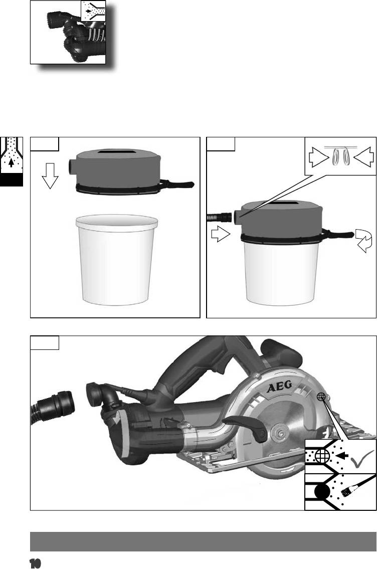
The dust produced when using this tool may be harmful to health.
the blade.
Do not inhale the dust. Use a dust absorption system and wear a
Do not reach underneath the workpiece.
The guard cannot
suitable dust protection mask. Remove deposited dust thoroughly,
protect you from the blade below the workpiece
.
e.g. with a vacuum cleaner.
Adjust the cutting depth to the thickness of the workpiece.
Appliances used at many di erent locations including open air should
Less than a full tooth of the blade teeth should be visible below the
be connected via a residual current device (FI, RCD, PRCD) of 30mA
workpiece.
or less .
Never hold piece being cut in your hands or across your leg.
Always disconnect the plug from the socket before carrying out any
Secure the workpiece to a stable platform.
It is important to
work on the machine.
support the work properly to minimize body exposure, blade binding,
Only plug-in when machine is switched o .
or loss of control.
Do not use inserted tools not corresponding to the key data given in
Hold power tool by insulated gripping surfaces, when
these instructions for use.
performing an operation where the cutting accessory may
Keep mains lead clear from working range of the machine. Always
contact hidden wiring. Cutting accessory contacting a „live“ wire
lead the cable away behind you.
may make exposed metal parts of the power tool „live“ and shock
the operator.
Before use check machine, cable, and plug for any damages or
material fatigue. Repairs should only be carried out by authorised
When ripping always use a rip fence or straight edge guide.
Service Agents.
This improves the accuracy of cut and reduces the chance of blade
binding.
Do not x the on/o switch in the “on” position when using the saw
hand-held.
English
19

Always use blades with correct size and shape (diamond
Lower guard function
versus round) of arbour holes.
Blades that do not match the
Check lower guard for proper closing before each use. Do
mounting hardware of the saw will run eccentrically, causing loss of
not operate the saw if lower guard does not move freely and
control.
close instantly. Never clamp or tie the lower guard into the
Never use damaged or incorrect blade washers or bolt. The
open position. If saw is accidentally dropped, lower guard may be
blade washers and bolt were specially designed for your saw, for
bent. Raise the lower guard with the retracting handle and make sure
optimum performance and safety of operation.
it moves freely and does not touch the blade or any other part, in all
angles and depths of cut.
Causes and operator prevention of kickback:
Check the operation of the lower guard spring. If the guard
and the spring are not operating properly, they must be
kickback is a sudden reaction to a pinched, bound or misaligned saw
serviced before use. Lower guard may operate sluggishly due to
blade, causing an uncontrolled saw to lift up and out of the workpiece
damaged parts, gummy deposits, or a build-up of debris.
toward the operator;
Lower guard should be retracted manually only for special
when the blade is pinched or bound tightly by the kerf closing down,
cuts such as „plunge cuts“ and „compound cuts.“ Raise lower
the blade stalls and the motor reaction drives the unit rapidly back
guard by retracting handle and as soon as blade enters the
toward the operator;
material, the lower guard must be released. For all other
if the blade becomes twisted or misaligned in the cut, the teeth at
sawing, the lower guard should operate automatically.
the back edge of the blade can dig into the top surface of the wood
Always observe that the lower guard is covering the blade
causing the blade to climb out of the kerf and jump back toward the
before placing saw down on bench or oor. An unprotected,
operator.
coasting blade will cause the saw to walk backwards, cutting
GB
Kickback is the result of saw misuse and/or incorrect operating
whatever is in its path. Be aware of the time it takes for the blade to
procedures or conditions and can be avoided by taking proper
stop after switch is released.
precautions as given below.
Please do not use abrasion disks in this machine!
Maintain a rm grip with both hands on the saw and position
your arms to resist kickback forces. Position your body to
SAFETY INSTRUCTIONS WHEN WORKING
either side of the blade, but not in line with the blade.
WITH DIAMOND CUTOFF WHEELS
Kickback could cause the saw to jump backwards, but kickback forces
can be controlled by the operator, if proper precautions are taken.
Read all safety warnings, instructions, illustrations and
When blade is binding, or when interrupting a cut for any
specications provided with this power tool. Failure to follow
reason, release the trigger and hold the saw motionless in
all instructions listed below may result in electric shock, re and/or
the material until the blade comes to a complete stop. Never
serious injury.
attempt to remove the saw from the work or pull the saw
Always use guard provided with the tool. The guard must
backward while the blade is in motion or kickback may occur.
be securely attached to the power tool and positioned for
Investigate and take corrective actions to eliminate the cause of blade
maximum safety, so the least amount of wheel is exposed
binding.
towards the operator. Position yourself and bystanders away
When restarting a saw in the workpiece, centre the saw blade
from the plane of the rotating wheel. The guard helps to protect
in the kerf and check that saw teeth are not engaged into the
operator from broken wheel fragments and accidental contact with
material. If saw blade is binding, it may walk up or kickback from
wheel.
the workpiece as the saw is restarted.
Use only diamond cut-o wheels for your power tool. Just
Support large panels to minimise the risk of blade pinching
because an accessory can be attached to your power tool, it does not
and kickback. Large panels tend to sag under their own weight.
assure safe operation.
Supports must be placed under the panel on both sides, near the line
The rated speed of the accessory must be at least equal to the
of cut and near the edge of the panel.
maximum speed marked on the power tool. Accessories running
Do not use dull or damaged blades. Unsharpened or improperly
faster than their rated speed can break and y apart.
set blades produce narrow kerf causing excessive friction, blade
Wheels must be used only for recommended applications. For
binding and kickback.
example: do not grind with the side of cut-o wheel. Abrasive
Blade depth and bevel adjusting locking levers must be tight
cuto wheels are intended for peripheral grinding, side forces applied
and secure before making cut. If blade adjustment shifts while
to these wheels may cause them to shatter.
cutting, it may cause binding and kickback.
Always use undamaged wheel anges that are of correct
Use extra caution when making a „plunge cut“ into existing
diameter for your selected wheel. Proper wheel anges support
walls or other blind areas. The protruding blade may cut objects
the wheel thus reducing the possibility of wheel breakage.
that can cause kickback.
The outside diameter and the thickness of your accessory
must be within the capacity rating of your power tool.
Incorrectly sized accessories cannot be adequately guarded or
controlled.
English
20
The arbour size of wheels and anges must properly t the
Kickback is the result of power tool misuse and/or incorrect operating
spindle of the power tool. Wheels and anges with arbour holes
procedures or conditions and can be avoided by taking proper
that do not match the mounting hardware of the power tool will run
precautions as given below.
out of balance, vibrate excessively and may cause loss of control.
Maintain a rm grip on the power tool and position your
Do not use damaged wheels. Before each use, inspect
body and arm to allow you to resist kickback forces. Always
the wheels for chips and cracks. If power tool or wheel is
use auxiliary handle, if provided, for maximum control over
dropped, inspect for damage or install an undamaged wheel.
kickback or torque reaction during start-up. The operator can
After inspecting and installing the wheel, position yourself
control torque reactions or kickback forces, if proper precautions are
and bystanders away from the plane of the rotating wheel
taken.
and run the power tool at maximum no load speed for one
Never place your hand near the rotating accessory. Accessory
minute. Damaged wheels will normally break apart during this
may kickback over your hand.
test time.
Do not position your body in the area where power tool will
Wear personal protective equipment. Depending on
move if kickback occurs. Kickback will propel the tool in direction
application, use face shield, safety goggles or safety glasses.
opposite to the wheel’s movement at the point of snagging.
As appropriate, wear dust mask, hearing protectors, gloves
Use special care when working corners, sharp edges, etc.
and workshop apron capable of stopping small abrasive or
Avoid bouncing and snagging the accessory. Corners, sharp
workpiece fragments. The eye protection must be capable of
edges or bouncing have a tendency to snag the rotating accessory
stopping ying debris generated by various operations. The dust
and cause loss of control or kickback.
mask or respirator must be capable of ltrating particles generated
by your operation. Prolonged exposure to high intensity noise may
Do not attach a saw chain woodcarving blade or toothed saw
cause hearing loss.
blade. Such blades create frequent kickback and loss of control over
GB
the power tool.
Keep bystanders a safe distance away from work area.
Anyone entering the work area must wear personal
Do not jam the cut-o wheel or apply excessive pressure. Do
protective equipment. Fragments of workpiece or of a broken
not attempt to make an excessive depth of cut. Overstressing
accessory may y away and cause injury beyond immediate area of
the wheel increases the loading and susceptibility to twisting or
operation.
binding of the wheel in the cut and the possibility of kickback or
wheel breakage.
Hold power tool by insulated gripping surfaces when
performing an operation where the cutting tool may contact
When wheel is binding or when interrupting a cut for any
hidden wiring or its own cord. Contact with a live wire will also
reason, switch o the power tool and hold the power tool
make exposed metal parts of the power tool live and shock the
motionless until the wheel comes to a complete stop. Never
operator.
attempt to remove the cut-o wheel from the cut while the
wheel is in motion otherwise kickback may occur. Investigate
Position the cord clear of the spinning accessory. If you lose
and take corrective action to eliminate the cause of wheel binding.
control of the power tool, the cord may be cut or snagged and your
hand or arm may be pulled into the spinning accessory.
Do not restart the cutting operation in the workpiece. Let
the wheel reach full speed and carefully reenter the cut. The
Never lay the power tool down until the accessory has come
wheel may bind, walk up or kickback if the power tool is restarted in
to a complete stop. The spinning accessory may grab the surface
the workpiece.
and pull the power tool out of your control.
Support panels or any oversized workpiece to minimize the
Do not run the power tool while carrying it at your side.
risk of wheel pinching and kickback. Large workpieces tend to
Accidental contact with the spinning accessory could snag your
sag under their own weight. Supports must be placed under the
clothing, pulling the accessory into your body.
workpiece near the line of cut and near the edge of the workpiece on
Regularly clean the power tool’s air vents. The motor’s fan will
both sides of the wheel.
draw the dust inside the housing and excessive accumulation of
Use extra caution when making a pocket cut” into existing
powdered metal may cause electrical hazards.
walls or other blind areas. The protruding wheel may cut gas or
Do not operate the power tool near ammable materials.
water pipes, electrical wiring or objects that can cause kickback.
Sparks could ignite these materials.
Do not use accessories that require liquid coolants. Using water
SPECIFIED CONDITIONS OF USE
or other liquid coolants may result in electrocution or shock.
Causes and operator prevention of kickback:
This electronic bercement saw can be used to cut wood or bre
cement with a circular saw blade. It can alternatively be used to cut
Kickback is a sudden reaction to a pinched or snagged rotating wheel.
stone with a diamant cutt-o wheel.
Pinching or snagging causes rapid stalling of the rotating wheel
Do not use this product in any other way as stated for normal use
which in turn causes the uncontrolled power tool to be forced in the
direction opposite of the wheel’s rotation at the point of the binding.
For example, if an abrasive wheel is snagged or pinched by the
workpiece, the edge of the wheel that is entering into the pinch point
can dig into the surface of the material causing the wheel to climb
out or kick out. The wheel may either jump toward or away from
the operator, depending on direction of the wheel’s movement at
the point of pinching. Abrasive wheels may also break under these
conditions.
English
21
ECDECLARATION OF CONFORMITY
We declare under our sole responsibility that this product is in
conformity with the following standards or standardized documents.
EN 60745, EN 55014-1, EN 55014-2, EN 61000-3-2, EN 61000-3-3, in
accordance with the regulations 2006/42/EC, 2004/108/EC
Rainer Kumpf
Winnenden, 2010-05-07
Manager Product Development
Authorized to compile the technical le.
MAINS CONNECTION
Connect only to single-phase a.c. current and only to the system
voltage indicated on the rating plate. It is also possible to connect
to sockets without an earthing contact as the design conforms to
safety class II.
MAINTENANCE
GB
Clean only with dry cloth. Certain cleaning agents and solvents are
harmful to plastics and other insulated parts. Keep the apparatus
handle clean, dry and free of oil or grease.
Use only AEG accessories and spare parts. Should components need
to be replaced which have not been described, please contact one of
our AEG service agents (see our list of guarantee/service addresses).
If needed, an exploded view of the tool can be ordered. Please state
the Article No. as well as the machine type printed on the label
and order the drawing at your local service agents or directly at:
AEG Elektrowerkzeuge, Max-Eyth-Straße 10, D-71364 Winnenden,
Germany.
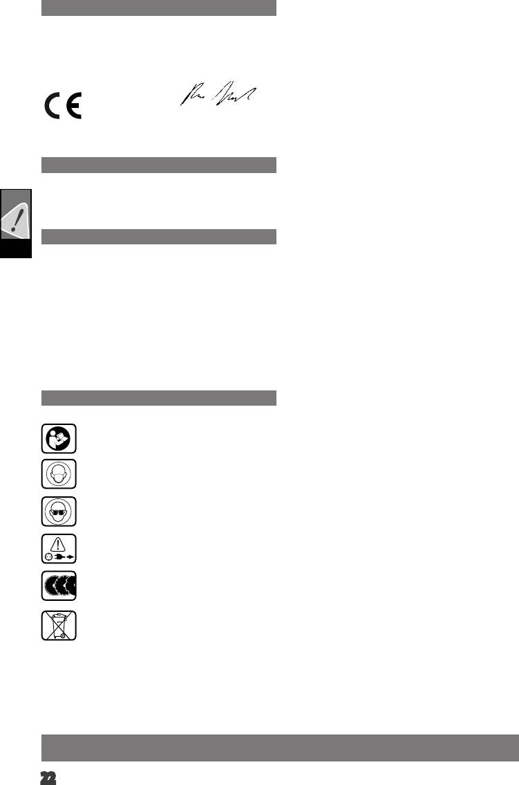
SYMBOLS
Please read the instructions carefully before starting
the machine.
Wear a suitable dust protection mask.
Always wear goggles when using the machine.
Always disconnect the plug from the socket before
carrying out any work on the machine.
Accessory - Not included in standard equipment,
available as an accessory.
Do not dispose of electric tools together with household
waste material! In observance of European Directive
2002/96/EC on waste electrical and electronic
equipment and its implementation in accordance with
national law, electric tools that have reached the end of
their life must be collected separately and returned to an
environmentally compatible recycling facility.
English
22


